 Andrew Kowalczyk
The circuit boards came in, and I assembled one for test. Only real issue was that I forgot the pull-up resistor and grounding capacitor on the reset line, shown below on a breadboard. I also added in a LED to act as a debugging indicator on P1.0. Those parts will be integrated into Rev 2, which should go out in the next week or two.
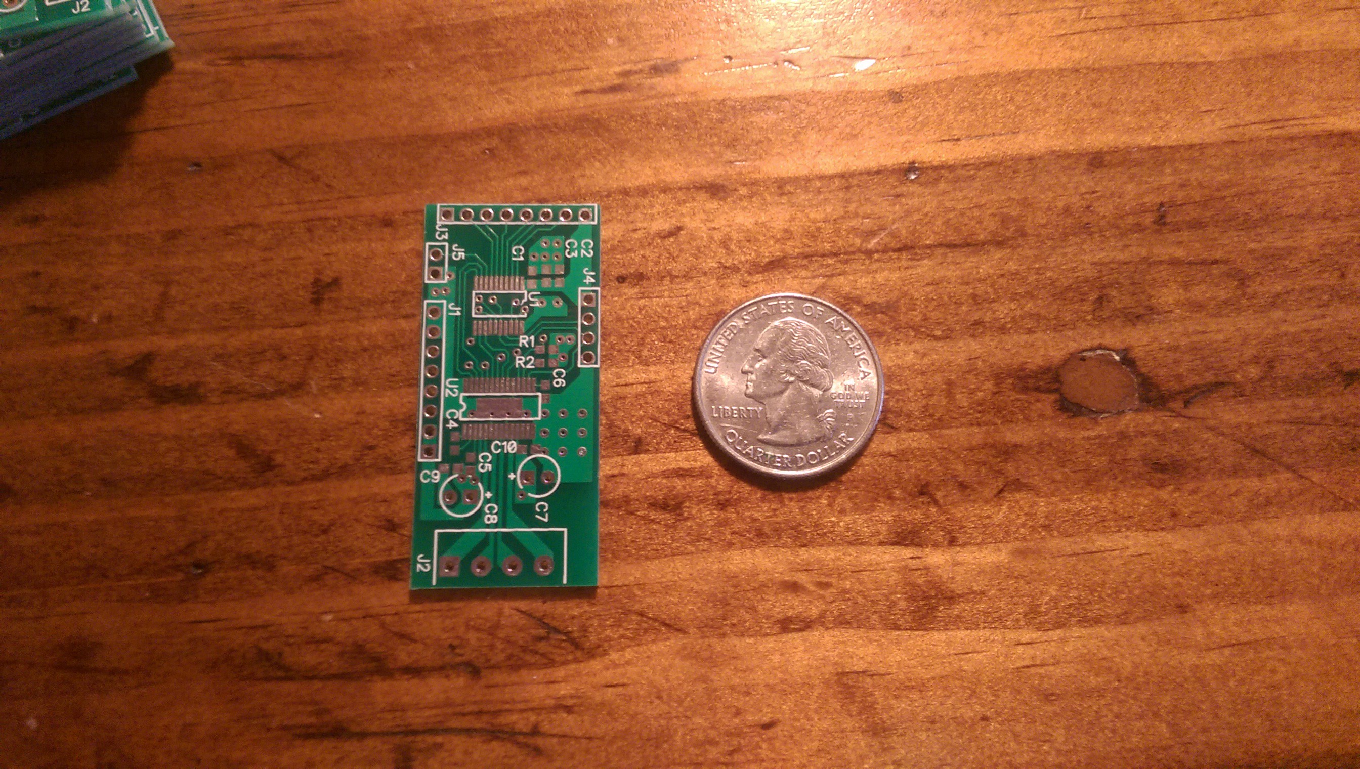
PCB with quarter for scale
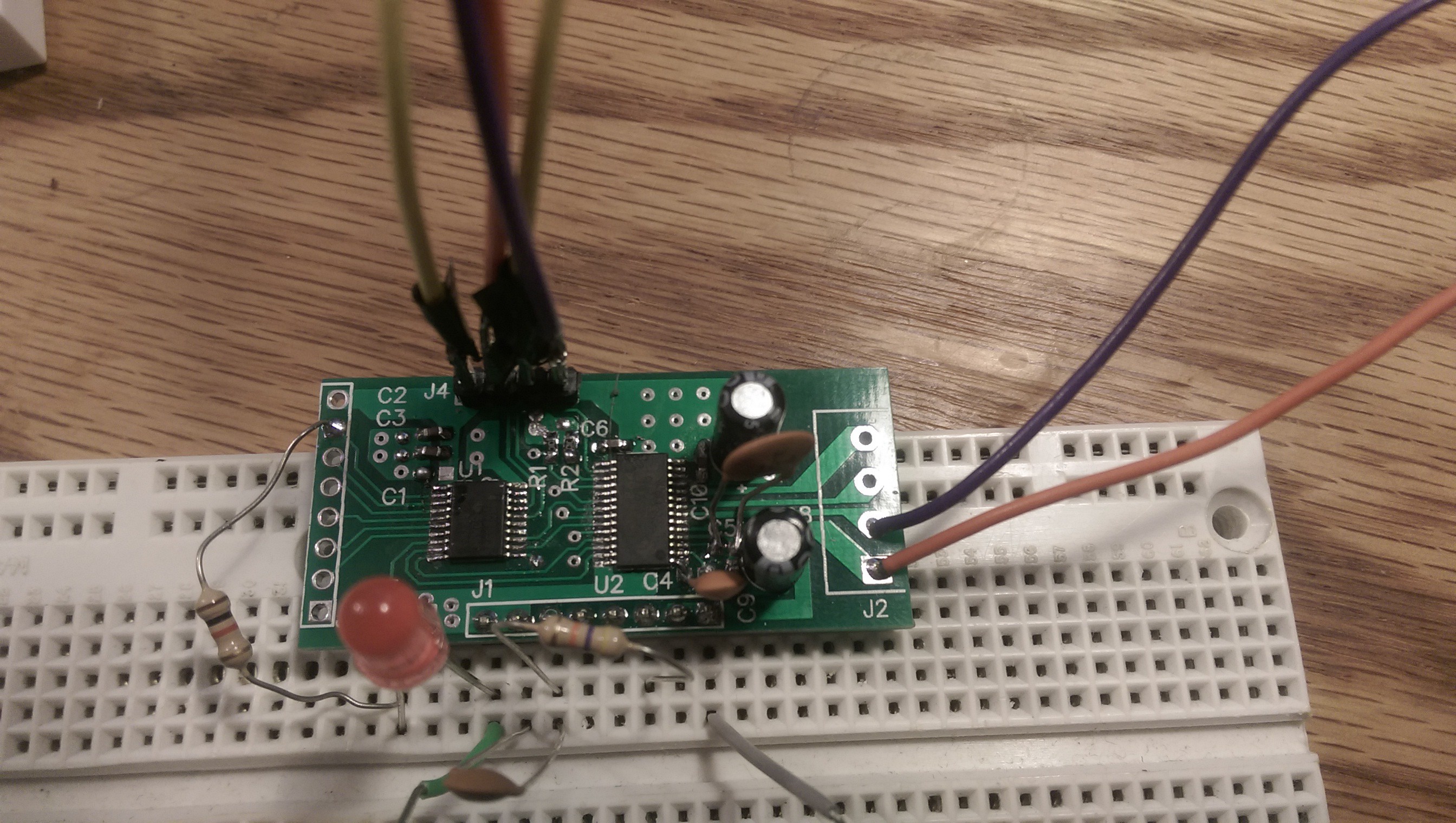
On breadboard, with a few extra components
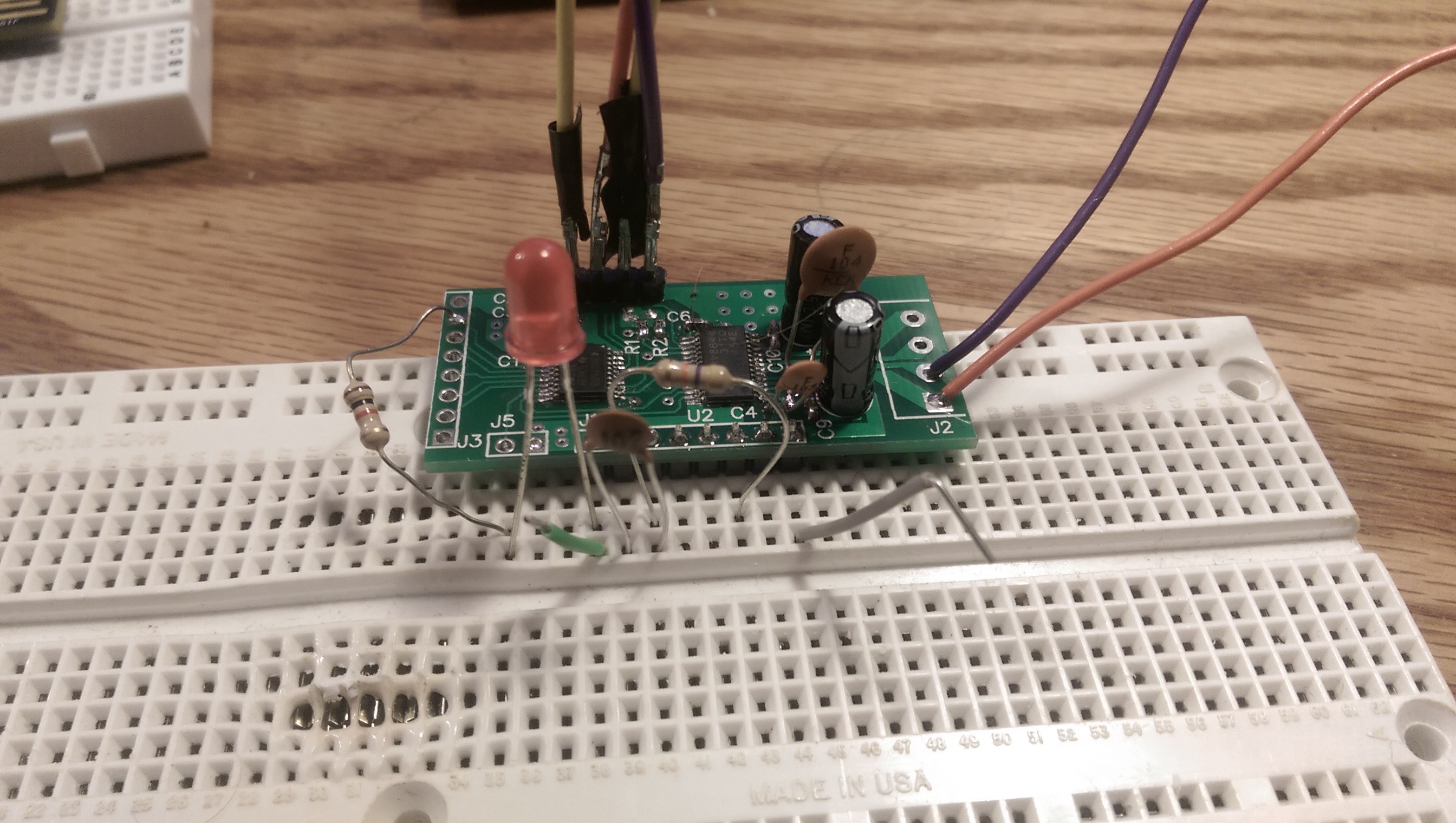
Slightly better view of what was added in
Once I was able to communicate with the MSP430, it was just a matter of turning on the motor power and giving it a whirl
Haven't tested I2C comms yet, that'll come in the next few days, but so far it's looking like the board works as an individual programmable motor controller.
Schematic and PCB for Rev 1 have been uploaded, but unless you want to bodge on the two components for Reset like I have, you might want to wait for Rev 2, which will be going out shortly
Discussions
Become a Hackaday.io Member
Create an account to leave a comment. Already have an account? Log In.