Bharbour
-
Built a Single Axis Version of this Board
06/28/2020 at 00:01 • 0 commentsIn an attempt to get rid of the radiated noise from the Theta Axis on my antenna rotator, I designed a single axis version of this board #Single Axis Step Motor Controller/Driver Board
Instead of using an Eval board, I put the CPU directly on the new board. In the time since designing the 3 axis board, I have changed CAD systems, so the new board was designed on the newer CAD system. The single axis board is close enough in design to this board, that I was able to test the single axis board with the firmware from this project with no modifications.
A new version of this board has been designed in the new CAD system, but has not been sent out for fabrication yet. It also has the CPU directly on the main PCB, has better power input filtering, and fixed the two blue wire mods needed on the original board. It is also smaller.
-
Live Testing of the Full System
08/07/2016 at 17:22 • 0 commentsProgress on the antenna rotator project has been slow. The amateur radio sats mostly use the 2 Meter and 70CM amateur bands (or close enough). A few of the sats use FM, but Sideband (SSB) is more common. I set up the rotator outside with a netbook computer to run the satellite tracking software and control the radio (a Yaesu 857D). A couple of discoveries were made:
The satellite RF frequency information in Gpredict (the satellite tracking software that I am using) is incomplete. When there is no frequency information for a satellite, it uses whatever values were left from the previous satellite. I need to research and write the frequency information for the rest of the amateur sats into the Gpredict database files.
The theta axis step motor radiates significant RF energy when enabled. This should not be too surprising, in that there is 3 feet of exposed cable carrying the step motor phase drives. I used foil shielded cable with the shield grounded to the case of the rotator. Running the radio in SSB mode on 145.8MHz and the theta axis enabled, the radio background noise level is around S9. When the theta axis is moving, you can hear the step pulse rate in the noise on the radio. With the theta axis off, the background noise level is around S4 or S5. Disabling the Azimuth and Elevation motors does not result in a detectable change in the background noise level. Similarly, removing the power into the rotator electronics makes a very minimal change in the background noise level. I need to put some VHF/UHF filtering on the theta axis motor wiring. I checked for RF emissions from the main body with a spectrum analyzer, and did not find any. It looks like I need to repeat that process with the theta axis installed and enabled to check the effectiveness of the filter changes.
I discovered the frequency database problem late in the day, toward the end of a pass by the FO-29 sat. Manually controlling the frequency and disabling the theta axis motor, I was able to hear CW traffic from the sat, so there is progress.
-
Built a second board up
02/01/2016 at 01:53 • 0 commentsNow that the rotator is complete, I built a second board up to investigate other possibilities for this design. After populating the board, I hooked up a TIVA eval board and flashed the current firmware. The power supplies were good but the motors were not switching on. It turned out that the SDA signal for the I2C bus that controls the motor configuration and current was shorted to the +3.3V, preventing the motor configuration and enabling. A few minutes under the microscope with a pick, cleared the short and the second board is working fine.
-
Built a Labview Front Panel for the Project
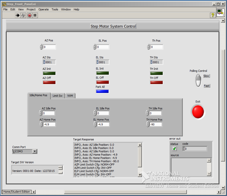
01/16/2016 at 21:28 • 0 commentsI recently got the low cost Labview Home version to install on my main lab machine. I wrote front panels to simplify mechanical setup and servo tuning for previous version of rotators using GTK and C. After using Labview at work for a number of projects, I decided to use it for the front panel on this rotator. I don't do enough GTK programming to be very conversant in it, and the previous implementations were semi-painful to do. This front panel implementation went very quickly and works well.
![]()
Because this rotator uses step motors, there is a lot less tuning required than the servo versions. As a result, this front panel is much simpler than what is required for the servo versions. Most of what is adjustable is related to the home switch offsets and the desired idle position for each axis. The limit switch configuration can be modified via the front panel, but since it is static for a given mechanical design, it is a low usage feature. The NVM operations available are Read NVM to RAM, Write RAM to NVM, and copy hardcoded default values to RAM and NVM.
This is the first RS232 interfaced system that I have worked with in Labview. In general, it is a lot more fiddly than the GPIB stuff that I normally work with. Liberal use of the buffer flush operation and automated retrys on some operations yielded a reliable interface.
-
The NVM code is working now. Firmware is now feature complete.
01/03/2016 at 23:22 • 0 commentsOver the holidays, I finished up the code to read and write to the I2C non-volatile memory chip. Now changes made to the system configuration can be saved and are automatically re-loaded each time the system powers up. It is time to put the cover on, and take it outside again with a laptop and a radio for live testing.
-
Mechanical/Electronic/Firmware integration is progressing well
12/26/2015 at 21:51 • 0 commentsI finished the mechanical system this morning, so the firmware is what needs to get done now. From the integration testing, the axes were moving too fast. The azimuth axis was missing steps because the accelleration was too high for the motor torque.The motion system generates a trapezoidal velocity profile (sort of) to make moves smoother and require less motor current. The full speed was 10x the initial velocity, so I slowed the top speed of the move down by a factor of 4 and the move velocity is good now. The beginning of the ramp velocity was not changed.
I added code for the automatic axis homing on power up. It can be enabled by axis with ifdefs, because the homing can be a pain to deal with while working on the mechanics.
-
Board will now run in stand alone mode
11/08/2015 at 00:10 • 0 commentsI was having problems getting the MCU to run without the debugger connected to the development IDE. After some digging around, it turned out that the vector table was not in the ROM code. I located a startup file from one of the example programs and carved it up to match my interrupt usage, and now the system will start up and run if not connected to the debug environment. I am using an older version of the Code Composer Studio (5.4) and it refused to generate the startup file when creating a new project. Hopefully the newer versions are better behaved in this respect.
There is a 5V regulator on my driver board to supply the Launchpad board power. It's a little quirky, in that you have to install a jumper if you want to run the system without a USB connection. The Launchpad boards are very USB centric, so they expect to run from the 5V VBus power on the USB debug connector. That VBus rail is brought out on the expansion connector, but back feeding the USB hub would likely cause problems, so there is a jumper to disconnect the on-board power from the VBus rail when using the USB connection.
The 32K boundary issue seems to have disappeared by magic. Adding the vector table and framework for the Non-Volatile-Memory operaion pushed up through the 32K bound and it loads and operates fine.
My day job is starting to get intense again, and so work on this project is going to take a back seat.
-
Firmware about 70% done
11/01/2015 at 04:01 • 0 commentsThe firmware is about 70% done. About 2/3 of the firmware in this project is re-used from a version that used DC servo motors instead of step motors. The system is accepting and interpretting all the required EZComm II commands to track satellites with the help of Gpredict. The biggest thing remaining to add to the firware is the NVM support to retain the system configuration long term. There are a few small features that I would like to add to the completed code, but they are in the nice to have category, not the required category.
Unfortunately, the tool chain is refusing to load more than 32K of code to flash. The executable code size is right around that boundary now. After adding a new command handler this morning, the debugger would not load the flash. I went in and cleaned out some debug code and was able to load and test the new commands. I suspect the 32K limit is a "feature" of the evaluation tools, because the data sheet on the MCU says it has 256K of flash. Believing that I had 256K to work in, I was not very thrifty with code space. If I have to, I can go in and re-do some stuff to free up extra space, but I would rather find a way around the 32K limit.
The EZComm II protocol is designed to support a 2 axis rotator (azimuth and elevation). Using a Yagi antenna to communicate with small satellites requires a 3rd axis (theta) to rotate the antenna on its centerline as the satellite rotates in orbit. Having your antenna 90 degrees out of the correct orientation can cost you 20 or 30dB of antenna gain which is a LOT. The protocol is simple enough that is easy to extend it in a consistent way to support the extra axis. The problem is that the satellite prediction packages don't know how to predict the theta position, as it is fairly random. Gpredict uses the Hamlib library to handle the hardware abstraction between the "standard rotator" and the actual one. I think I can wedge some extra code into Hamlib to give me manual control of the theta axis. This is an issue for another day.
-
Default Stack Size too small on project
10/27/2015 at 01:10 • 0 commentsTesting the limit switches with simple firmware in a loop was crashing the MCU. After some digging, I determined that calls to snprintf() were what triggered the crash. After some web searching on the vendors web site, I found references to the default stack size needing to be increased to use snprintf. When I looked at the setting in the project, it was 512 bytes which seems ridiculously small for that MCU with 256K of flash and 32K of RAM. Upped the stack size to 4K and all the problems went away. When the real firmware gets closer to done, I will check the stack high water mark and adjust it from there.
Fun with a new tool chain...
-
Connectors arrived
10/27/2015 at 01:08 • 0 commentsThe connectors that I ordered for the other two motors arrived today and after installing, all motors are moving as they should. This is now a firmware project!
Stepmotor Driver Board for TI Tiva Launchpad
Three axis stepmotor driver, limit switch conditioning and power supplies.