Dave Vandenbout
-
A Small Success
10/15/2015 at 19:36 • 6 commentsI built another CAT Board with a minimal amount of circuitry (i.e., the FPGA, voltage regulators, RESET switch, some pullup resistors) and powered it up. I looked at the SPI clock signal and it had a 7.5 MHz square wave on it. That's exactly what it should do if the FPGA is powering up in master configuration mode and trying to load a bitstream from an external serial flash. I could also toggle the reset and see the FPGA putting out commands to the flash on the SDO line.
I was also able to place the FPGA in the slave serial mode by holding its SPI slave-select pin low while pulsing the reset. So I felt I was ready to try configuring it from the RPi.
I mounted the four LEDs on the CAT Board and then connected the power, ground and SPI signals to the RPi. Then I used the bash script to download the simple LED driver bitstream to the FPGA. Here's a video of the event:
So I've verified that I can create valid iCE40 bitstreams with the iCEcube2 software and download them to the iCE40HX FPGA from the RPi. Now I can assemble the rest of the CAT Board and continue testing with the RPi.
As to what went wrong with the first board I assembled, possibly I toasted the FPGA by heating it too long (2:00 minutes). I heated the second BGA for only 1:30 minutes. As I recall, I ruined the first Xilinx BGA I ever attempted to mount, so I'm keeping the tradition alive.
-
Square 1
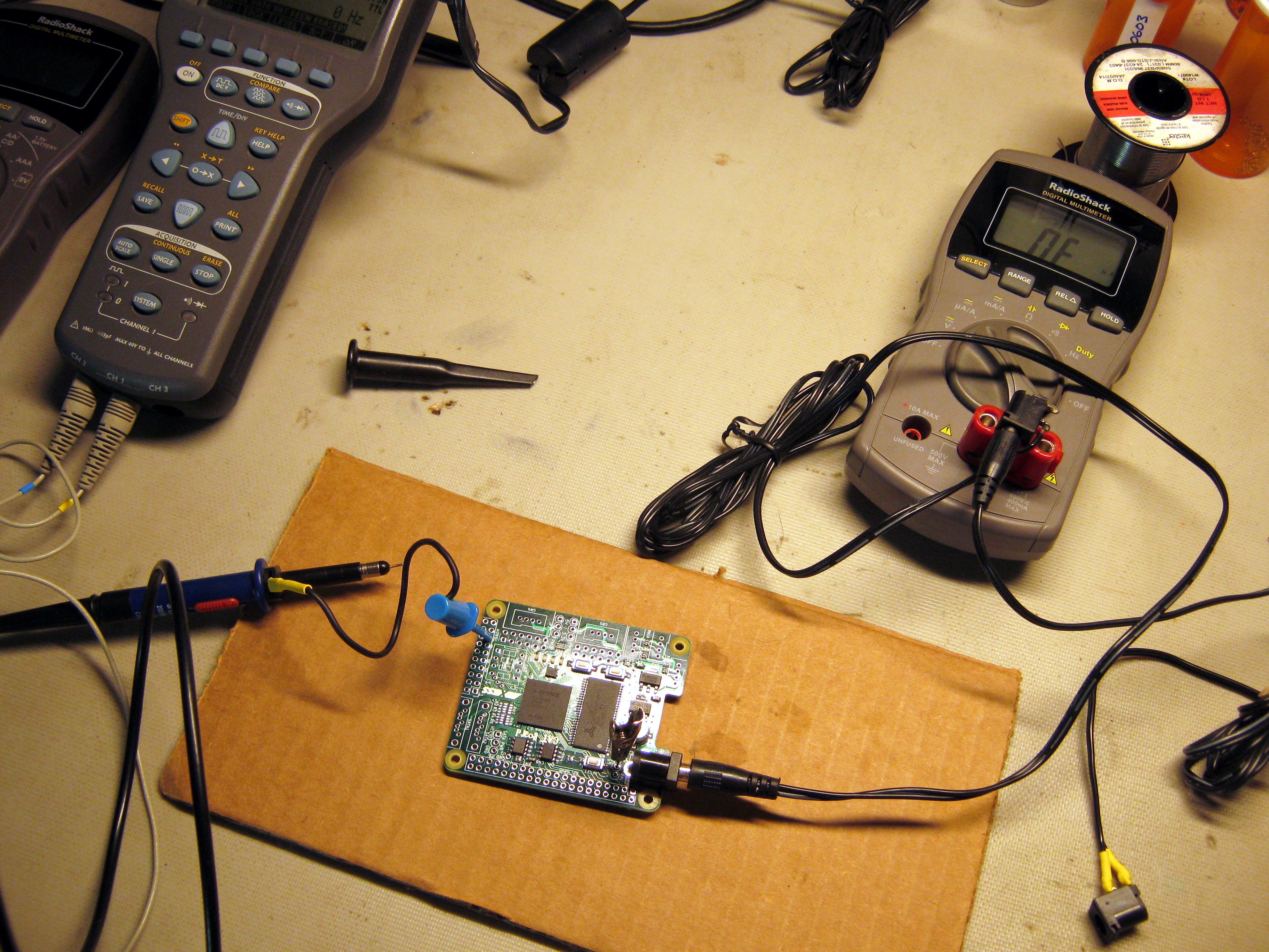
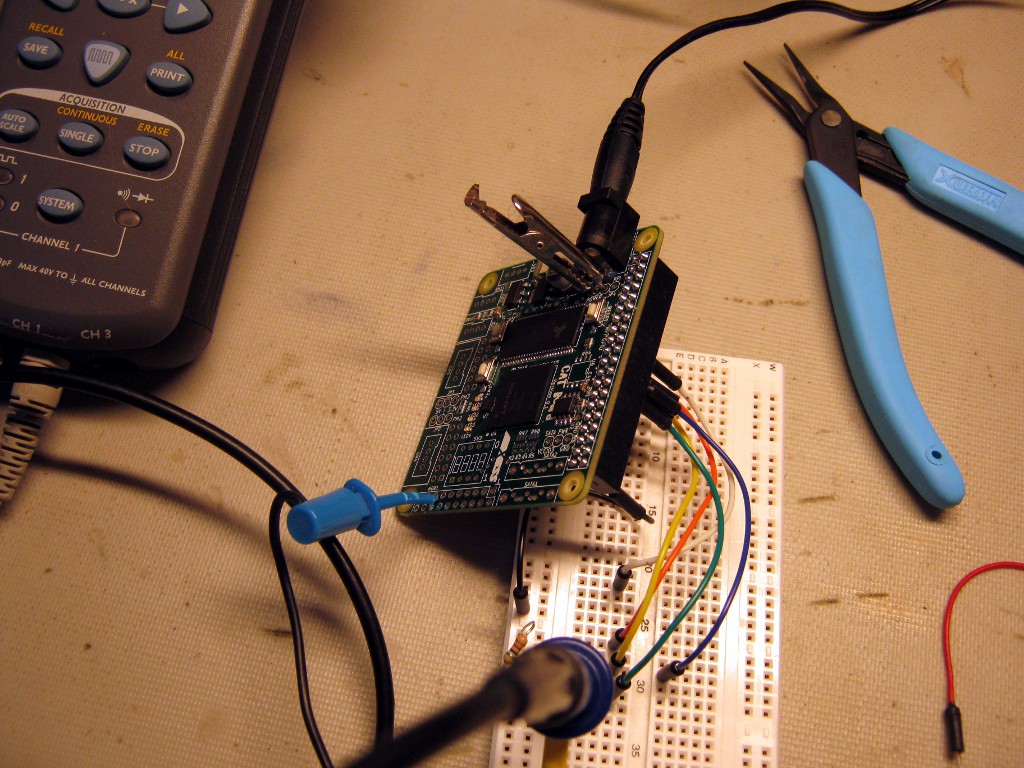
10/15/2015 at 15:21 • 0 commentsGiven the problems I've had trying to configure in slave mode using the RPi, I decided to see if the FPGA would configure itself in master mode. So I removed the CAT Board from the RPi and made connections to the power, ground, SPI I/O, and RESET like this:
![]() The serial flash has been removed so there's no way the FPGA can actually configure itself, but it should at least try to read in a bitstream. But toggling the RESET or power supply didn't produce any activity on the SPI clock line. It's possible the FPGA is completely dead.
The serial flash has been removed so there's no way the FPGA can actually configure itself, but it should at least try to read in a bitstream. But toggling the RESET or power supply didn't produce any activity on the SPI clock line. It's possible the FPGA is completely dead.My plan now is to place an FPGA on another CAT PCB with a minimal amount of extra circuitry (mainly the voltage regulators) and see if that shows any signs of life.
-
Dammit, Why Don't You Just *WORK*!
10/15/2015 at 05:19 • 3 commentsWell, the title kind of says it all. So far, there's been no success getting the FPGA to configure.
I attached the CAT Board to the RPi, transferred the FPGA bitstream to the RPi, and installed the shell script for downloading the bitstream to the FPGA. Then I executed the command `config_ice leds_bitmap.bin` and ...
Nothing.
OK, I really didn't think it was going to work the first time. So I used the oscilloscope to check various signals:
- The RESET signal to the FPGA was going up and down, so it wasn't stuck at zero and holding the FPGA in a reset state.
- The BCM25 signal was going low to set the FPGA in the slave serial configuration mode.
- The SPI clock signal that clocks the bitstream into the FPGA was toggling.
- The SDI data signal that carries the bitstream was toggling, but it was spending a lot of its time at 2V instead of being at 0V or 3.3V.
The SDI signal looked like it was butting heads with another output trying to drive the FPGA's SDI input. My first thought was that the serial flash chip used to store the FPGA bitstream was being enabled and trying to send its contents at the same time the RPi was. Looking at the shell script, I could see it kept BCM25 pin pulled low during the entire configuration sequence and this would have enabled the serial flash. I revised the script by pulling BCM25 high after the FPGA reset went high because the FPGA would have entered the slave mode by then. Then I executed the script again and ...
Nothing.
OK, I wasn't really expecting it to work the second time. I looked at the SDI signal and it still showed contention. Possibly the RESET signal wasn't enough to put the FPGA in the slave serial configuration mode. Maybe it had to have its power cycled to do that.
So I removed the CAT Board from the RPi and restarted the script. When the script asked me to toggle the power to the FPGA, I just re-attached the CAT Board. (Previously, I had just toggled the RESET.) Then the script finished and ...
Nothing. Jesus!
OK, nothing good happens without some effort. Maybe I should check the RPi to make sure it's operating like I think. So I removed the CAT Board and re-ran the script while looking at the GPIO pins (which were now driving empty space). All the signals, including the SDI, were transitioning cleanly between 0V and 3.3V.
So it wasn't the RPi. Was the serial flash was still misbehaving? To test that, I desoldered that chip and re-ran the script ...
Nothing. Dammit!!
When I looked at the SDI with the serial flash removed, the SDI signal was still showing contention. That seemed to indicate the SDI pin on the FPGA was acting as an output instead of an input, which would happen if the FPGA was acting as a master instead of a slave.
So I went back to the Lattice appnote on configuring the iCE40 FPGA. One statement struck me: "An SPI slave mode configuration image must not use the Cold Boot or Warm Boot options." I was (and am) certainly no expert at using the iCEcube2 IDE, so maybe I had enabled one of these options.
I looked at my simple LED project and, sure enough, I had enabled warm boot in the bitstream options. I disabled that and rebuilt the bitstream. (I couldn't find the cold boot option. Hopefully it's off.) Then I ran the bitstream downloading script. Surely this has to work now ...
Nothing. Nothing from you, you goddamn, motherfucking, piece of SHIT!
So at this point it's time to reassess the situation and list some possible causes for failure:
- The design was incorrectly compiled so the bitstream won't work.
- The bitstream was compiled correctly, but it got corrupted when transferring it from the PC to the RPi.
- The bitstream is OK, but the FPGA isn't getting into the slave mode.
- I've criss-crossed the FPGA's SDI and SDO pins so I'm trying to inject the bitstream into an output pin. (There is some contradiction between the iCE40HX datasheet and the configuration appnote as to the operation of these pins in master versus slave mode.)
- One or more pins of the FPGA weren't soldered when I mounted the FPGA's BGA using the heat gun.
There's probably more, but those are the first things that spring to mind. So here's my current plan of action:
- I ordered an iCEstick from Mouser. That will give me a known-good board I can use to test the generated bitstream and the RPi interface.
- If the iCEstick works with my bitstreams and RPi, then I'll start cutting-up the board and try swapping the SDI and SDO pins.
- If the SDI/SDO swap doesn't work, I'll try reheating the BGA to see if I can close any potential opens between the balls and the PCB.
- If reflowing doesn't work, I'll remove the BGA completely and probe the pads to make sure the PCB traces are not broken.
- If the traces are OK, I'll mount another FPGA and try again.
I'm not discouraged by this. As the little kid said when presented with a roomful of dung on Christmas morning: "All right! There's got to be a pony in there somewhere!"
-
Oh, *That's* What Happened!
10/13/2015 at 06:26 • 2 commentsSo I had that problem with the polarity-protection MOSFET. It looked like it wasn't coming on and it was throttling the input supply voltage. But I couldn't reconcile the voltages I was seeing to the voltage/current curves of the DMP3098. There's no way the voltage could drop that much across the device with that small a current and a Vgs of almost four volts. Plus, I was bothered by the non-existent current drawn by the CAT Board.
So I went back and recreated the same setup. Sure enough, I saw the same voltages as before. But this time I measured the voltage on both the MOSFET drain (attached to the power supply) and the source (connected to the 5V plane on the PCB). And they were both 3.8V. (I had not measured the drain voltage before, just assuming it was 5V.)
So something was knocking-down the supply voltage before it even got to the board. The only thing between the supply and the board was the ... wait a minute! I had assumed the ammeter was showing a negligible current flowing into the board because it displayed this:
![]()
What my meter was actually trying to tell me was it had 0verFlowed the particular range I had selected. When I changed the dial from the microamp range to the milliamp range, the supply voltage on the drain and source of the MOSFET popped up to 5V and all the regulator outputs went to their expected values.
Some internal circuitry in the ammeter had impeded the supply voltage when the current exceeded the allowable range. What threw me off is that this effect goes away if the supply voltage is increased a volt or two, causing me to incorrectly blame the MOSFET threshold voltage.
Once the ammeter was setup correctly, I saw the board draws a quiescent current of 22mA. Here are the typical quiescent currents for the devices on the board:
Device Current (mA) AZ1117EH-3.3 linear regulator 4.0 AZ1117EH-1.2 linear regulator 4.0 AZ1117EH-ADJ linear regulator 4.0 CAT24C32 I2C serial flash 0.001 AT25SF041 SPI serial flash 0.010 iCE40HX8K FPGA 1.16 AS4C16M16S-6 SDRAM 2.0 501ACA100M 100 MHz oscillator 7.6 TOTAL 22.76 That's pretty close to what I'm seeing. Now I can go forward with some belief that the power circuitry is correct.
The rest of my test plan was as follows:
- Attach the CAT Board to the RPi and see if they blow up.
- Install the yocto RPi image with the IceStorm tools and generate a blinking LED bitstream.
- Download the bitstream to the CAT Board and see if it works.
I'm revising that. If the LED fails to blink, then the problem could be any one of these (or more):
- The yocto image is corrupt.
- I'm using the IceStorm tools incorrectly.
- I bollixed-up the LED blinker design: doesn't run, wrong clock input, wrong LED outputs, etc.
- The RPi GPIO pins that download the bitstream to the FPGA aren't configured as outputs.
- The bitstream is corrupted, either when generated or during downloaded.
I'm too old and tired to fight the entire gang, but, yeah, I think I can take them one-on-one. So here's my revised test plan:
- Download the iCEcube2 programming tools from Lattice and install them on my Windows 7 PC.
- Create a simple, non-clocked circuit that displays a static pattern on the CAT Board LEDs.
- Compile the circuit using the iCEcube2 tools to get a known-good bitstream. (Known-good in the sense the bitstream is valid for the iCE40HX8K FPGA, not that the design actually works.)
- Mate the CAT Board with an RPi that uses my existing Raspian distribution which I know already works.
- Transfer the bitstream from my PC to the RPi.
- Use this technique to download the bitstream to the CAT Board.
- If the correct pattern doesn't appear on the LEDs, then the problem is probably a corrupted bitstream caused by transferring from the PC to the RPi or by the downloading through the GPIO pins.
- If the correct pattern does appear, then install the yocto image and repeat the download of the bitstream.
- If the bitstream download still works, then recompile the design using the yosys + arachne-pnr tools and test the new bitstream.
- If the bitstream compiled with the open-source tools works, then create a blinking LED circuit and try that.
Each step minimizes (as much as possible) the number of new elements introduced into the test. If a step fails, then there's only a few places to check for a problem.
So far, I've completed steps 1 through 4. Here's the VHDL for the initial design. I'm hoping I didn't screw that up. Guess I'll find out tomorrow.
library ieee; use ieee.std_logic_1164.all; use ieee.numeric_std.all; use ieee.math_real.all; entity leds is port ( led_o : out std_logic_vector(4 downto 1) := "0101" ); end entity; architecture arch of leds is -- declare signals, components here... begin led_o <= "1010"; end architecture; -
Initial Power Up
10/11/2015 at 04:17 • 1 commentI've always said a project is a success if you can turn it on and not have to pick pieces of it out of your face afterwards. By that measure, the CAT Board is a success.
I didn't get that much done today. I had to wrap presents for a birthday party later in the day, and I talked with my sister about her parrot that escaped from her house. But I did manage to get a few steps into my testing plan.
First, I measured the connectivity of the voltage and ground planes. I didn't find any shorts between any of them. So far, so good.
Then I connected a 5V supply to the external power jack with an ammeter in series. No current! I measured the voltages and the 5V was down to 3.7V, the 3.3V was down to 2.8V, and the 1.2V was at 1.2V. It turns out the P-channel MOSFET I'm using for polarity protection wasn't fully turning on and was dropping the 5V. Looks like I'm going to have to find a MOSFET with a lower threshold than the DMP3098L-7.
![]()
I rummaged around in my big box of power adapters and found a 6V supply with the proper polarity and a 2.1 mm plug. Plugging that in seems to provide enough oomph to get the MOSFET conducting. All the voltage regulator outputs went to their specified values.
But still no current! Turns out I'm used to FPGAs that draw 30 mA of static current, but the iCE40 is intended for low-power applications so it doesn't do that. Typical current to the FPGA core is 1.14 mA, but I'm not even seeing that. Possibly the FPGA goes into an even lower power mode if it isn't loaded with a valid bitstream.
I measured the output of the 100 MHz oscillator and saw the 100 MHz clock (actually, with my scope, I saw a 100 MHz sine wave). I also checked the reset button: yep, the FPGA reset gets pulled low when the button gets pressed.
That was about as far as I got. Tomorrow I'll continue, mostly with getting the RPi configured with the IceStorm tools. I won't have much time to do that since I have to go down to my sister's farm later in the day.
Gotta find that damn bird.
-
Hand Assembly
10/10/2015 at 03:32 • 7 commentsI finished putting most of the SMD components on the CAT Board. Mostly bypass caps (around forty of those). I've left off the through-hole stuff since that isn't needed for the immediate tests.
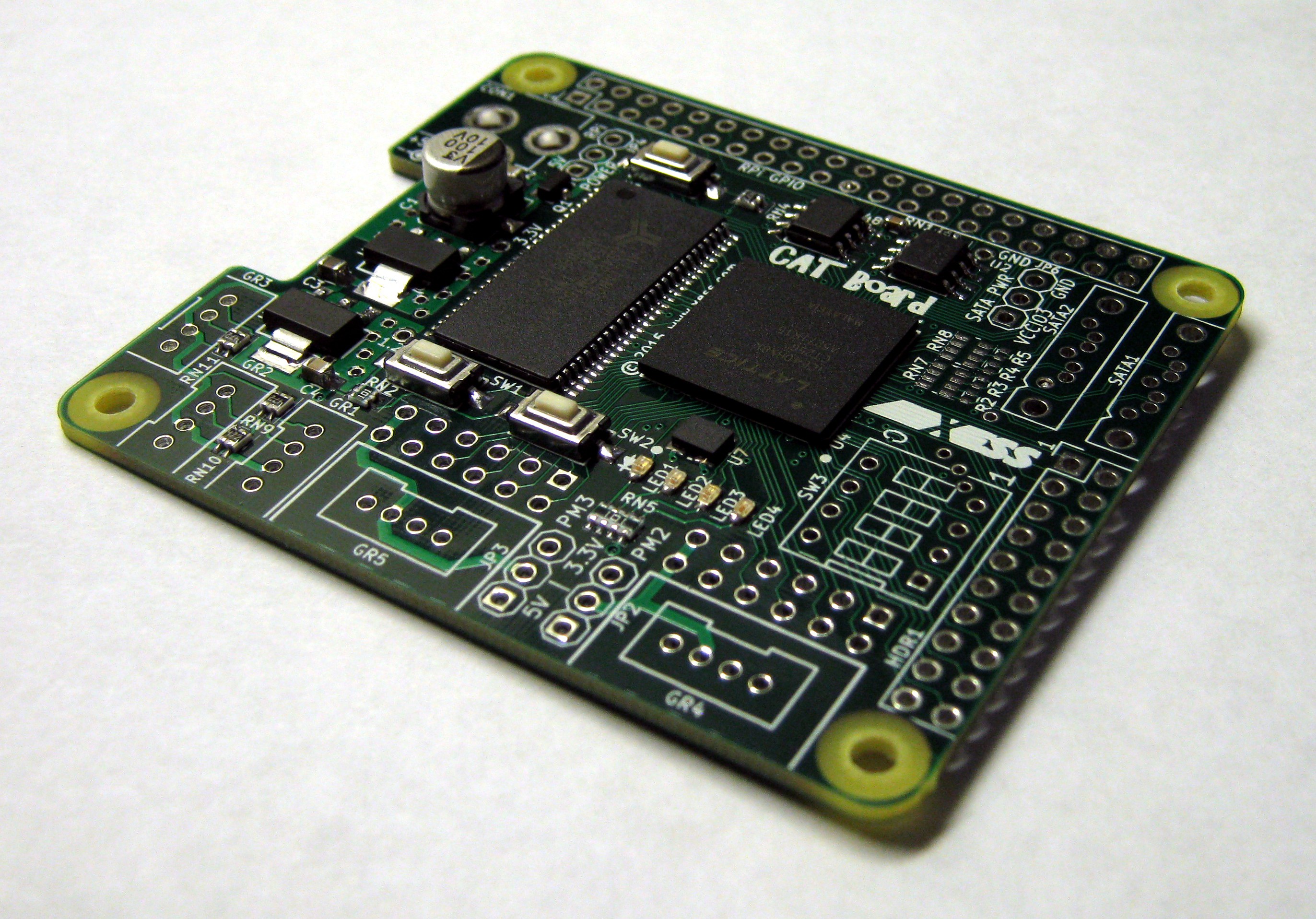
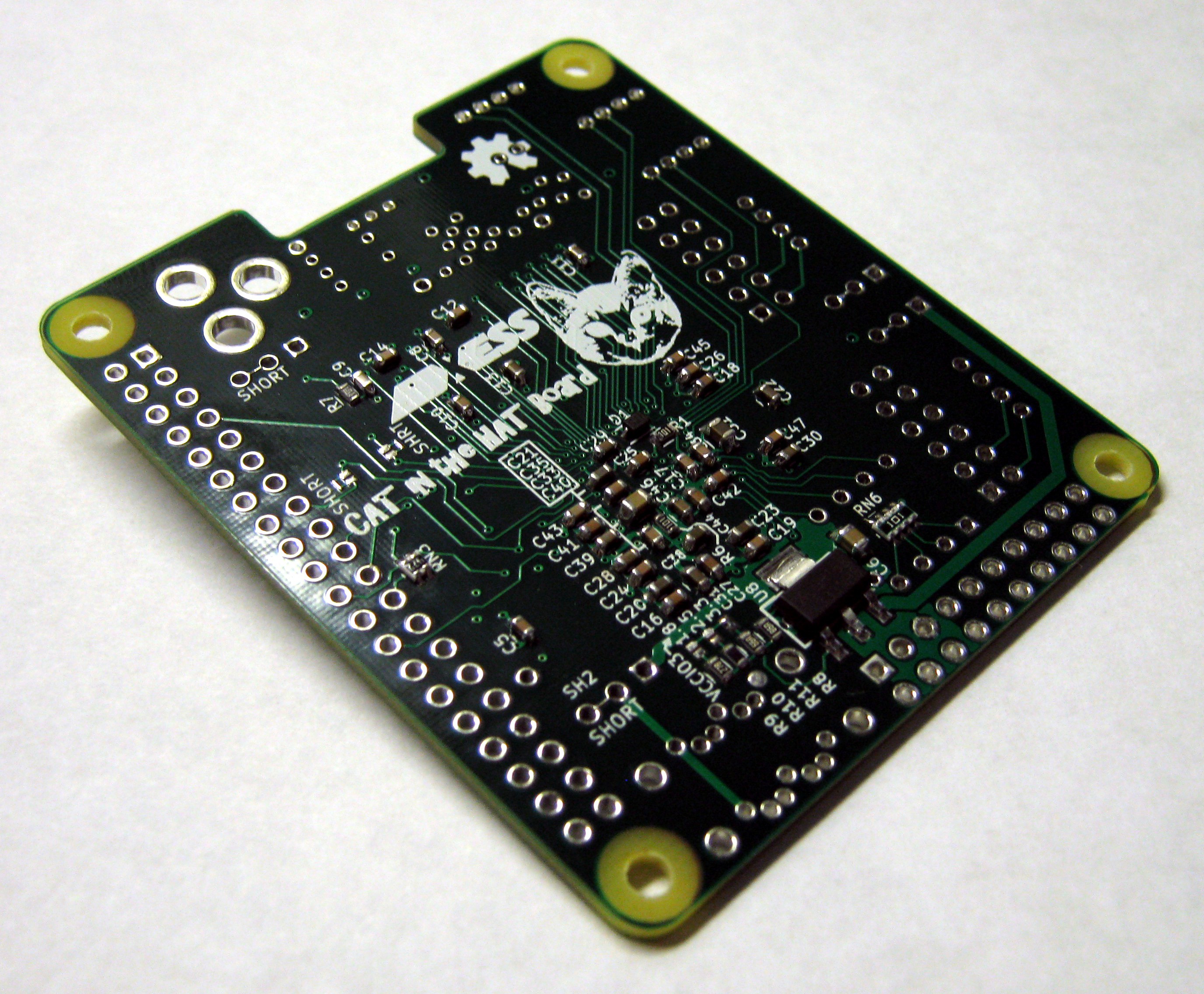
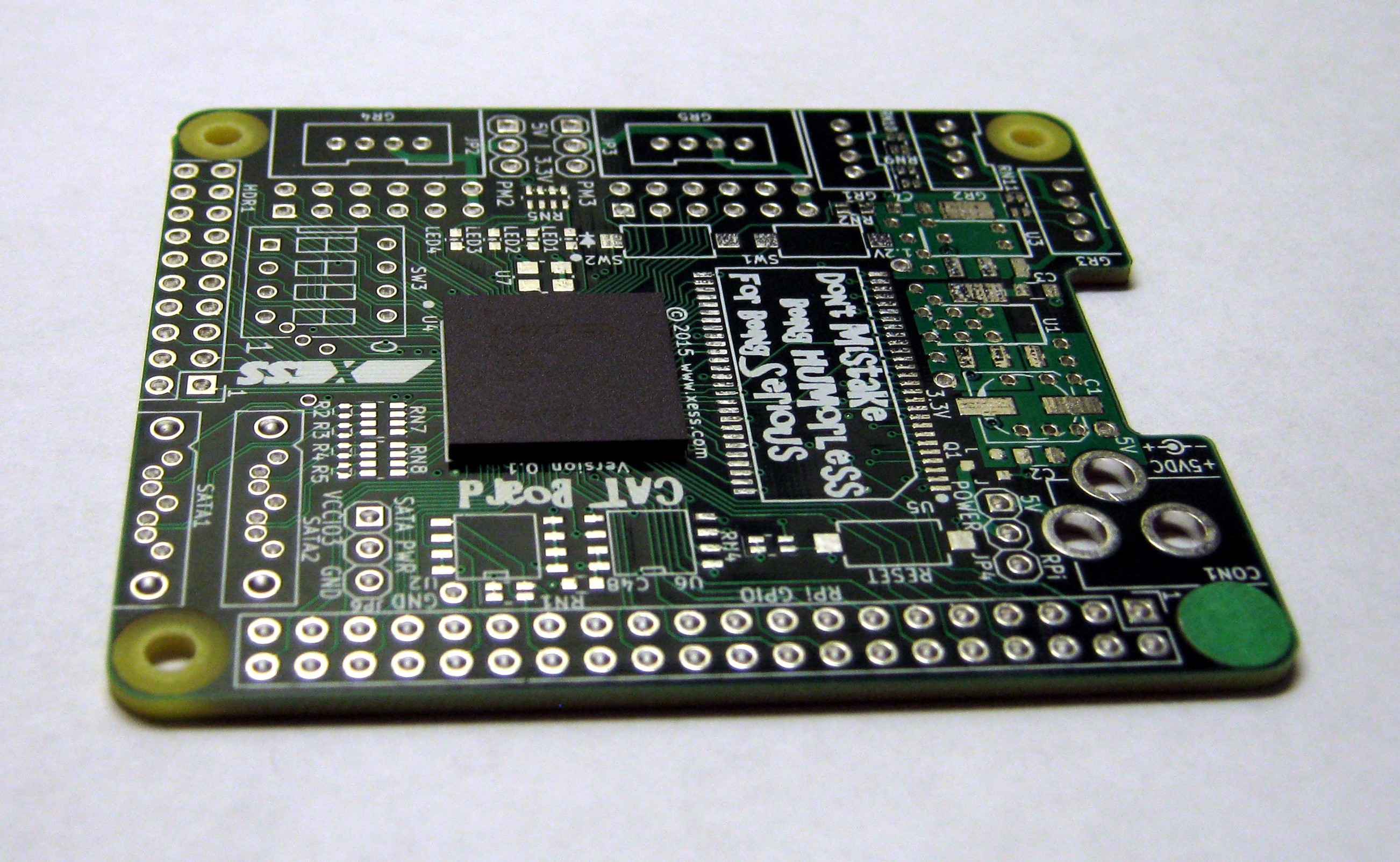
Here's the front and back:
![]()
![]()
Initial testing starts tomorrow:
- Check for power/GND shorts.
- Check voltage regulator levels and current draw from 5V supply.
- Plug it into a Raspberry Pi and see if one or both die.
- Install Ed's yocto image with the IceStorm tool flow and generate a bitstream for a blinking LED.
- Download the bitstream to the CAT Board and see what happens.
-
BGA Mounting on the Cheap
10/09/2015 at 04:48 • 2 commentsToday I selected one of the best boards for the initial prototype. I probed it with a continuity tester to make sure the voltage planes (5V, 3.3V, 1.2V, VCCIO3 and GND) were not shorted and that each plane was connected to the correct pins of the iCE40's BGA package. I also checked the BGA pins surrounding each power supply pin to see if any of them were shorted to power or ground.
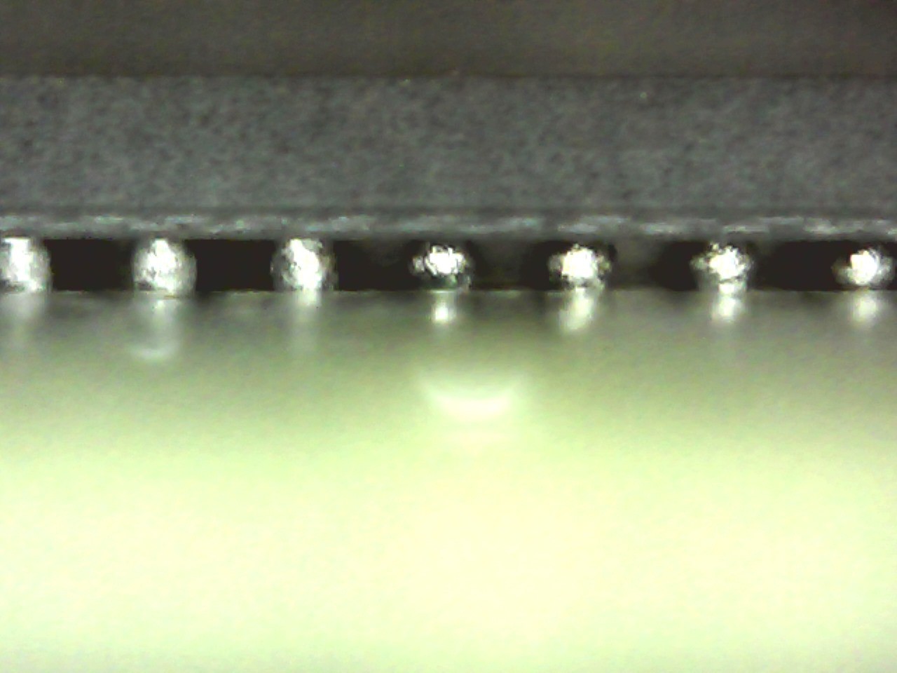
After verifying there were no shorts or opens on the power planes, I mounted the BGA onto the CAT PCB using the method illustrated below.
Afterwards, I used a $50 USB microscope to examine the BGA solder balls. The solder balls haven't collapsed uniformly, but it's good enough for the prototype. Shining a bright light from one side of the BGA while looking into the opposite side also showed the absence of any shorts between adjacent columns or rows. Of course, there's still the problem of opens in the interior but I can't check for those without an X-ray machine.
So the BGA is on there. The rest of the assembly is just soldering-iron work.![]()
![]()
-
PCB Inspection
10/08/2015 at 03:07 • 0 commentsAfter publishing the initial video about this project on YouTube, I inspected each of the eleven PCBs with a USB microscope. Here's the amount of soldermask misalignment I found:
Soldermask Misalignment #PCBs 1 mil 3 2 mil 5 3 mil 3 So I've got eight usable PCBs and three that I could use in a pinch.
I also had a couple of recent OSHPark PCBs, so I decided to check them. Misalignment on those was about 0.5 mils or less. It would have been nice to have that tight registration, but they don't offer the 4 mil trace/space and 8 mil drills that I needed.
CAT Board
The CAT Board is part of a Raspberry Pi-based hand-held FPGA programming system.
 The serial flash has been removed so there's no way the FPGA can actually configure itself, but it should at least try to read in a bitstream. But toggling the RESET or power supply didn't produce any activity on the SPI clock line. It's possible the FPGA is completely dead.