Dave Vandenbout
-
Another KiCad Tool, Another Decision
06/11/2018 at 02:58 • 0 commentsOver the past few weeks, I've done two things related to his project:
- Wrote a plugin for KiCad's PCBNEW that lets you paint pads of specific types.
- Prototyped a vertical HDMI connector and decided it wasn't worth it.
Pad Painter
When you're dealing with FPGAs having several hundred or more pins, most of which are interchangeable, it can be perplexing when trying to choose the correct pin to connect to some other peripheral. You want to choose one that's close to where it will be connected, but you also need to make sure it's the right type (don't connect an FPGA VCC pin to an HDMI connector data pin), and it's in the right I/O bank. I wrote the PadPainter plugin for KiCad to highlight pads of ICs that meet a set of conditions such as the electrical function (input, output, bidirectional, etc.) and the bank (or unit) to which its assigned. This tool quickly shows me the pins of the FPGA which are candidates for connection to other peripherals. If you're dealing with large FPGAs or SOCs, this tool may also be useful to you. You can read more about it here.
Vertical HDMI Connector
I decided to replace the SATA connectors on the original CAT Board with an HDMI port. Because of its location, the normal right-angle HDMI connector would be blocked by the USB ports of the Raspberry Pi. So I decided to use a vertical connector.
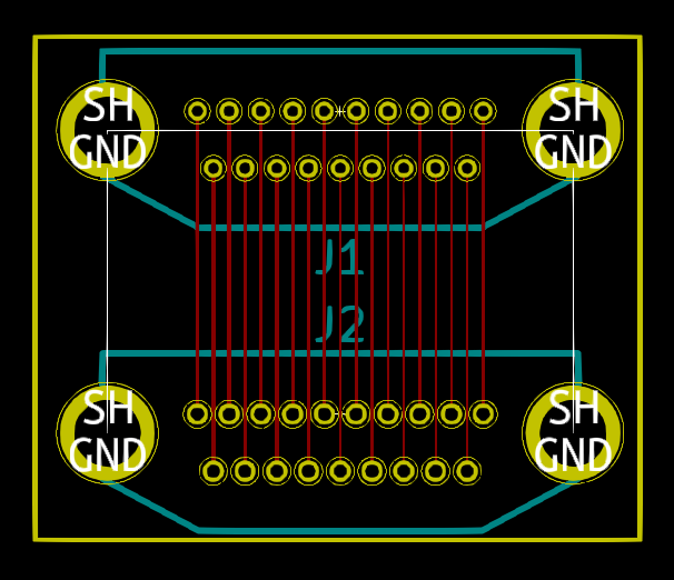
Finding vertical HDMI connectors wasn't easy. Digikey and Mouser didn't have any. I finally found some on Aliexpress, but I had to piece together the footprint dimensions from several sources. Obviously, I couldn't really trust my footprint so I built a small prototype board using several hole sizes and trace/space widths:
![]()
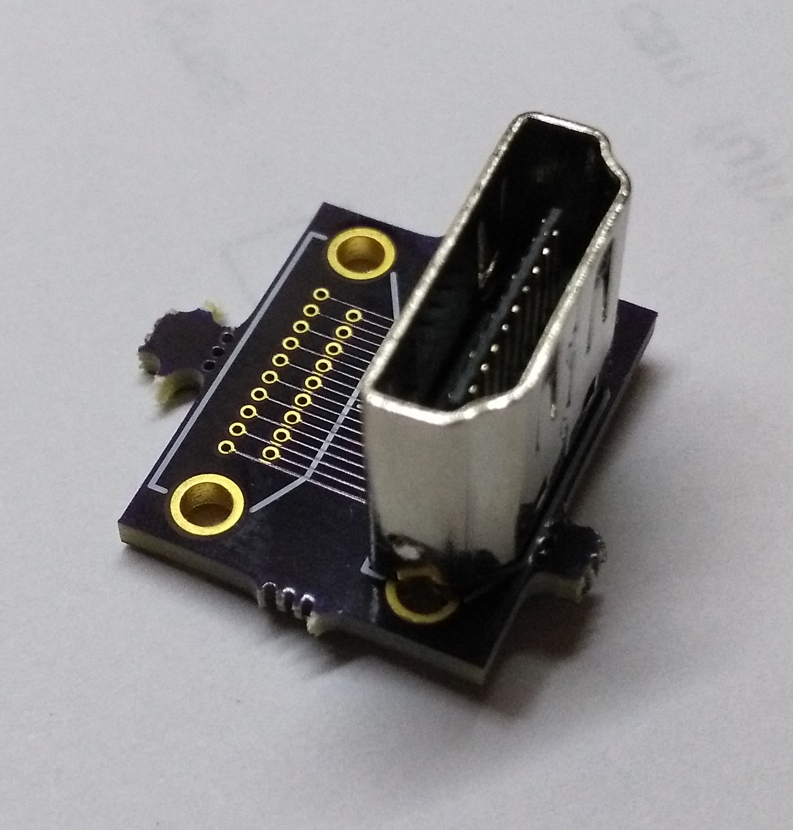
The PCB showed my footprint would work with the vertical HDMI connector:
![]()
Even so, I decided not to pursue this any further. The choice of suppliers for the connector was too limited and sketchy, and the assembly process looked like bent pins would be a problem.
Instead, I'll use the more common right-angle HDMI connector and bring it off the same side of the PCB that's used by the Raspberry Pi GPIO connector. To make room, I'll need to replace the through-hole GPIO socket with an SMT version.
-
A Pile of Parts
05/28/2018 at 02:39 • 0 commentsIn my last log, I had the SKiDL-generated netlist imported into an RPi HAT template. The problem with that is PCBNEW initially places all the parts pretty much any way it wants. That means you have to pick through a pile of parts to find which ones go with which. As an example, I highlighted (in white) the SDRAM chip and its bypass caps:
![]()
My solution for this problem was two-fold:
- Since SKiDL descriptions are just programs with a natural hierarchy, I modified SKiDL to pass that hierarchy to PCBNEW by embedding it into the sheetpath fields of the netlists it generates.
- Then I wrote a plugin for PCBNEW that would group and arrange the parts to reflect their position within that hierarchy.
With those two items in place, the relationships between the parts becomes much clearer. Here's the placement of the SDRAM and its bypass caps now:
![]()
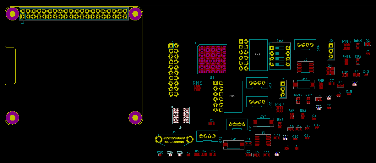
After that, I was able to create an initial, rough placement for the CAT Board:
![]()
I still have to design the +3.3V and +1.2V voltage regulator circuits. After those are done, I can begin the detailed placing and routing.
-
CAT Board in SKiDL
05/20/2018 at 15:01 • 0 commentsIt's been a few weeks since my last log post. Since then, I've done the following:
- Created SKiDL modules for each of the blocks shown in my last log post, except for the power section. I still haven't selected the voltage regulators for that.
- Wrote a blog post describing how to do parameterized SKiDL modules for LED circuits. This is also directly applicable to the switch and pushbutton sections of the CAT Board.
- Released a version update for SKiDL that includes improvements motivated by the need to simplify/condense the SKiDL description of the CAT Board.
- Merged the SKiDL-generated netlist for the CAT Board with my KiCad template for Rapsberry Pi HATs.
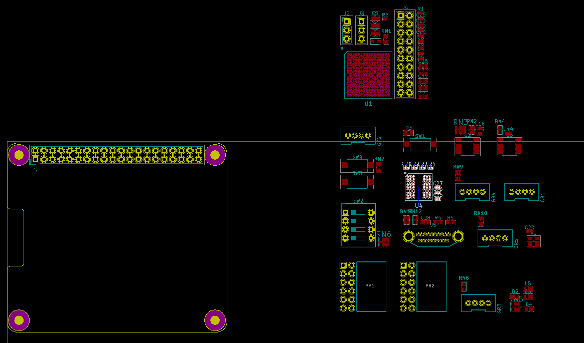
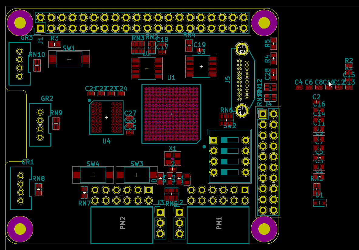
With regard to the last item on the list, here are the components and the HAT PCB boundary:
![]()
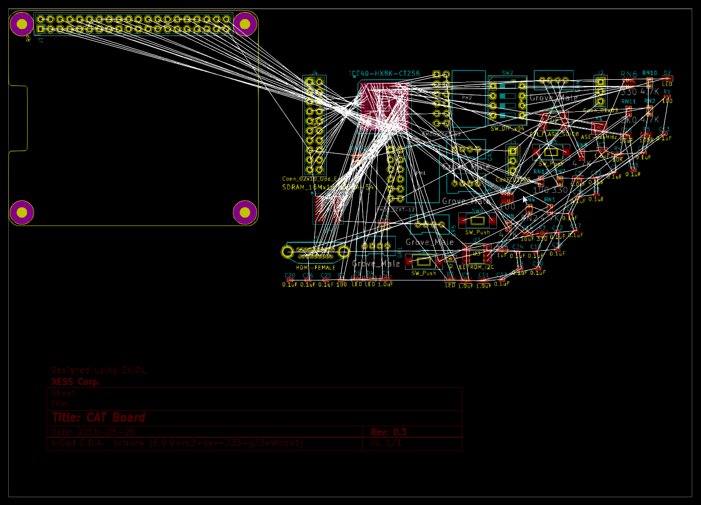
And here it is with the air-wires:
![]()
So I've got my crap. I've got my bag. Now it's a question of whether I can get all my crap in my bag.
The current state of the CAT Board is stored in the skidlized branch of the CAT Board repository.
-
Conversion to SKiDL
05/04/2018 at 14:07 • 0 commentsThe first step in this resurrection was to convert the schematic-based CAT Board design into a SKiDL program. That was actually pretty easy. First, I generated a netlist from within EESCHEMA. Then I ran the following program to convert it into a SKiDL program:
netlist_to_skidl -i cat.net -o cat-flat.pyWhile the conversion was easy, it's not exactly what I want. The resulting code is flat: just a list of component instantiations and nets to interconnect them without any hierarchical structure. Making changes to that is no easier than hacking on the actual netlist file.
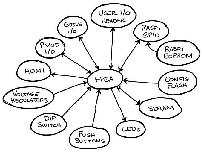
The actual hierarchy for the CAT Board is shown below. It isn't a deep tree: just a bunch of peripherals attached to a central FPGA. But my goal is to make a parameterized SKiDL module for each peripheral. Then I can build not only the CAT Board by interconnecting those modules, but reuse them in other designs as part of a circuit library. A simple example would be an LED module that instantiates multiple LEDs and current-limiting resistors based upon the width of the bus entering the module.
![]()
So why did I bother making the flat version of the SKiDL code? Some of the motivation was to show the use of the netlist_to_skidl utility since it's an easy way to generate SKiDL for those used to working with schematics. In addition, the flat code also includes the detailed templates of the components used in the CAT Board. I can reuse those in my parameterized version.
-
Resurrection
05/02/2018 at 02:39 • 1 commentMy last log post for this project was over 1-1/2 years ago, but I'm returning to it now with the following objectives:
- Rebuild the design using the SKiDL design language.
- Replace the power supply section with smaller LDO/switching regulators.
- Replace the large DC jack with a micro-USB connector that will be compatible with a Raspi power supply.
- Replace the SDRAM in the TSSOP-54 package with a smaller VFBGA version.
- Replace the two SATA connectors with an HDMI connector.
- Add the PCB slot for the Raspi camera flex cable.
Rebuilding the CAT Board using SKiDL will guide me in adding features to make the language more expressive and concise. The remaining changes will improve the capabilities of the board while possibly compacting the circuitry enough so I can get all the components on a single side of the PCB.
Also, I took advantage of a StickerMule special to get 50 vinyl stickers for just $9. It'd be a shame to have these and no new board to go with 'em.
![]()
-
It Just Keeps Getting Easier!
09/25/2016 at 13:10 • 0 commentsI learned about a new FOSS project a few weeks ago: apio. It's stated mission is:
Experimental open source micro-ecosystem for open FPGAs. Based on platformio. Apio is a multiplatform toolbox, with static pre-built packages, project configuration tools and easy commands to verify, synthesize, simulate and upload your verilog designs.
That sounded pretty good to me. It was easy to install on my RPi3:
pip install apio
That just installs the apio "shell". In order to get all the synthesis, simulation, and board tools, I used the command:apio install --all
That automatically downloads and installs some system utilities, the Icestorm FPGA toolchain, the iverilog simulator, and some design examples for several types of iCE40 FPGA boards. Once that was completed, I could check to see what boards were supported:
pi@raspberrypi:~ $ apio boards --list

Supported boards:

--------------------------------------------------------------------------------
Board         FPGA                 Type  Size  Pack
--------------------------------------------------------------------------------
icoboard      iCE40-HX8K-CT256     hx    8k    ct256
icezum        iCE40-HX1K-TQ144     hx    1k    tq144
icestick      iCE40-HX1K-TQ144     hx    1k    tq144
go-board      iCE40-HX1K-VQ100     hx    1k    vq100
iCE40-HX8K    iCE40-HX8K-CT256     hx    8k    ct256

Use `apio init --board <boardname>` for creating a new apio proyect for that board
What!?!? No CAT Board in the list!?! I needed to fix that situation. I poked around in the apio Python code and found a likely file at apio/resources/boards.json. Inside that file, I pretty much copied the existing entry for the icoboard with a few modifications:"Cat-board": { "fpga": "iCE40-HX8K-CT256", "prog": "litterbox", "check": { "arch": "linux_armv7l" } }The only thing I changed (besides the board identifier) was the "prog" entry to list the litterbox utility that uploads bitstreams from the RPi3 to the FPGA on the CAT Board.I also had to modify the following section of the SConstruct file in the same directory:
# -- Upload the bitstream into FPGA
upload_cmd = ''
if PROG == 'ftdi':
    upload_cmd = 'iceprog{0} -d i:0x0403:0x6010:{1} $SOURCE'.format(
        EXT, DEVICE)
elif PROG == 'gpio':
    # Icoboard + RPI2: sram
    upload_cmd = 'export WIRINGPI_GPIOMEM=1; icoprog -p < $SOURCE'
elif PROG == 'litterbox':
    # Cat Board + RPI2,3
    upload_cmd = 'sudo litterbox -c $SOURCE'
This just adds the command for uploading a bitstream using the litterbox utility.
Finally, after a little more poking around, I found the apio/managers/scons.py file and added the following code to its upload function:
        # -- Litterbox
        elif programmer == 'litterbox':
            # Cat Board + RPI2,3
            # Device argument is ignored
            if device and device != -1:
                click.secho(
                    'Info: ignore device argument {0}'.format(device),
                    fg='yellow')
            # Check architecture
            arch = self.resources.boards[board]['check']['arch']
            current_arch = util.get_systype()
            if arch != current_arch:
                # Incorrect architecture
                click.secho(
                    'Error: incorrect architecture: RPI2 or RPI3 required',
                    fg='red')
                return 1
This does a sanity check to make sure the upload process for the CAT Board is occurring on an RPi2 or RPi3.
Now when I regenerate the board list, I can see the CAT Board:
pi@raspberrypi:~ $ apio boards --list

Supported boards:

--------------------------------------------------------------------------------
Board         FPGA                 Type  Size  Pack
--------------------------------------------------------------------------------
icoboard      iCE40-HX8K-CT256     hx    8k    ct256
icezum        iCE40-HX1K-TQ144     hx    1k    tq144
Cat-board     iCE40-HX8K-CT256     hx    8k    ct256
icestick      iCE40-HX1K-TQ144     hx    1k    tq144
go-board      iCE40-HX1K-VQ100     hx    1k    vq100
iCE40-HX8K    iCE40-HX8K-CT256     hx    8k    ct256

Use `apio init --board <boardname>` for creating a new apio proyect for that board
Once my modifications were complete, I went into the directory for the LED blinker and used the following command to indicate that this design was intended for the CAT Board:
apio init --board Cat-board
This creates an apio.ini file with a single line of text indicating the board type:
{"board": "Cat-board"}From there, it's an easy step to compile the design and upload it to the CAT-board:
apio upload
If the bitstream in the directory is missing or out of date, apio will rebuild the design using the Icestorm tools. Then it uploads the bitstream to the CAT Board using the litterbox utility. After that, the LED starts blinking. Success!The apio tool makes it really easy to install and apply the iCE40 FPGA tools. Also, the authors have added my modifications so apio now supports the CAT Board right out of the box.
-
That Was Fast!
09/01/2016 at 16:38 • 3 commentsI've been away from this project for a few months (OK, four months) building things like a new tool for designing electronics. One of the things I haven't discussed here is the time it takes to download a bitstream to the FPGA on the CAT Board.
As shown in previous logs, the FPGA is configured through one of the hardware SPI ports of the RPi. I've never considered SPI a very fast way of transferring data, so I initially set the port bit rate at 1 Mbps. That was good enough to get the FPGA going within a couple of seconds and there was no reason to push it and possibly cause errors while I debugged the board.
But once the board was working reliably, I revisited the SPI bit-rate setting. I figured there was no harm in upping it to 5 Mbps just to see what happens. I went into the litterbox.py script and changed it to:
self.spi.speed = 5000000Then I ran the command to load the FPGA with the bitstream for the LED blinker:sudo litterbox -c blinky.bin
The download to the FPGA completed more quickly than before and the LED started blinking. Success!
Then I started pushing for more: 10 Mbps, 20 Mbps, 50 Mbps, no problem; 100 Mbps, 150 Mbps, still five-by-five; 200 Mbps, complete and utter failure.
OK, I hadn't expected to get even close to 200 Mbps. With a little trial and error, I finally found the maximum speed I could use was 199,999,999 bps. The reason for that becomes clear later.
Now, was I actually transferring bits at 200 Mbps, or was the software making a promise that the hardware couldn't keep? To test that, I wrote some code to time the transmission of a 10 MByte payload and compute the effective bit-rate while I also observed the maximum SPI clock frequency and duty cycle with an oscilloscope:
spi.speed (Mbps) Actual Speed (Mbps) Fmax (MHz) Duty Cycle (%) 4 1.8 2.5 --- 10 3.3 6.25 54.0 25 8.8 25 36.1 50 10.7 50 21.7 67 11.3 67 17.9 100 12.0 100 12.1 150 12.0 100 12.1 200 12.8 200 6.4 As can be seen, the actual transmission speeds are quite a bit lower than the speed setting. The reason for that is the overhead in the python-spi module that copies and converts the individual 4096-byte packets of the payload before sending them to the SPI driver. Even though each packet gets transmitted at a high clock speed, there's a significant "dead time" (2.3 ms) while the software readies the next packet. As the raw speed increases, the packet transmission time decreases and the dead time (which stays constant) consumes a larger percentage of the time to send the full payload. That's why the duty cycle decreases as the speed setting increases.
To decrease the overhead, I modified the python-spi code as follows:
- The data payload is checked and no conversion or copying is done if it is already in the form of a string of bytes.
- The address of the current packet within the payload is sent to the SPI device driver rather than making a copy of the packet.
After these two changes, setting spi.speed to 100 Mbps resulted in an actual transmission speed of 65 Mbps (an increase of 540%).
There's no reason to set the spi.speed to a value greater than 100 Mbps. The table indicates the RPi is generating the SPI clock by dividing a master 200 MHz clock by an integer. Any setting between 100 and 199 Mbps will result in an SPI clock of 100 MHz, and going to 200 Mbps has already proven too fast for sending an FPGA configuration bitstream. (The iCE40HX datasheet also shows the SPI clock in slave mode should not exceed 25 MHz, so getting to 100 MHz is really pushing it already.)
A transfer rate of 65 Mbps opens up some interesting possibilities. That means there is an 8 MByte/second channel between the CAT Board FPGA and the RPi that uses only a few pins of the GPIO connector. I have some Xilinx-centric VHDL modules and a Python library that provide a printf-like debug interface for FPGA designs through the JTAG port. I can modify these to use the SPI port so the CAT Board + RPi will have the same capabilities. I'll be working on that next. I think. Maybe.
-
Getting to Blinky, MyHDL Style!
05/09/2016 at 23:34 • 2 commentsIn my previous post, I showed how to blink an LED on the CAT Board using Verilog. Now I'll do the same thing using MyHDL, a hardware description language based on Python.
I'll assume a starting point of a Raspberry Pi running the Raspbian OS with the yosys, arachne-pnr and icestorm FPGA tools installed. If you're following along and haven't already got that, read the previous post. The stuff I describe here won't work without it.
Install MyHDL
Before you can use MyHDL, you have to install it. Installing the latest release is as simple as:
sudo pip install myhdlBut I like to use the development version because that's where all the new features are. That's installed like this:
cd /opt
sudo git clone https://github.com/jandecaluwe/myhdl.git
cd myhdl
sudo python setup.py install
Blinky in MyHDL
Blinking an LED with Verilog wasn't hard, and doing it in MyHDL isn't either. Here's the source code that's stored in a Python file called blinky.py.
from myhdl import *

# Define the Blinky module.
@block
def blinky(clk_i, led_o):

    cnt = Signal(intbv(0, 0, 50000000)) # Counter from 0 to 49999999.
    tgl = Signal(bool(0)) # Toggle flag drives the LED.

    # Sequential block triggered on every rising edge of the clock.
    @always_seq(clk_i.posedge, reset=None)
    def toggle_led():
        if cnt == cnt.max-1: # When the counter reaches its max value...
            tgl.next = ~tgl  # Toggle the flag...
            led_o.next = tgl # Output the flag to the LED...
            cnt.next = 0     # Reset the counter.
        else: # Counter hasn't reached max so just keep incrementing.
            cnt.next = cnt + 1

    # Return a reference to the Blinky logic.
    return toggle_led

# Define the connections to Blinky.
clk_i = Signal(bool(0))
led_o = Signal(bool(0))

# Create an instantiation of Blinky.
top = blinky(clk_i, led_o)

# Output Verilog code for Blinky.
top.convert(hdl='Verilog')
Compiling to Blinky
The blinky.py file containing the MyHDL code shown above is executed as follows:
python blinky.pyThis translates the MyHDL code into Verilog that's stored in the blinky.v file. Then this Verilog file can be compiled into a bitstream using the yosys, arachne-pnr and icepack tools just like in the previous post. Once the bitstream is downloaded to the CAT Board, the LED will blink.
Raison de'Etre
Why bother doing this in MyHDL? It just adds another step, but does it add any value?
In this case, no, it doesn't. Because this design is so simple, the MyHDL code isn't any more compact or expressive than the original Verilog. The value of MyHDL is experienced when doing design exploration, i.e. trying various approaches to solving a problem. Then all the features of the Python ecosystem can be used with MyHDL to come up with a solution. I showed a few examples of this here and here.
-
Getting to Blinky, CAT Board Style!
05/02/2016 at 03:51 • 5 commentsA fundamental rite of passage is getting your embedded system to blink an LED. In this post, I'll show you how to take a Raspberry Pi 3 fresh out of the box and get an LED blinking on the CAT Board.
(If you're already experienced with the RPi, then a lot of this post will be redundant for you. However, I've found it useful to document processes so I can repeat them reliably at a later date when the details have grown fuzzy.)
Install the OS
The first thing to do is install an operating system (OS) on the RPi:
- Get the Raspbian OS for the RPi and unzip it on the PC.
- To write the OS image to the SD card, get the Win32DiskImager and install it on the PC.
- Use the Win32DiskImager to write the Raspbian OS to an SD card inserted in the PC. (This will take a while.)
SSH Over Ethernet
I'm going to use the RPi by connecting to it over a network SSH connection from my PC:
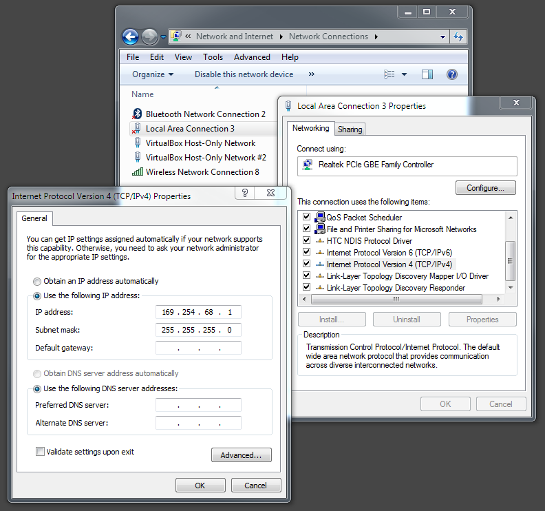
- Look in Network Connections to find the IP address of an Ethernet port the RPi can attach to.
![]()
- Go into the SD card and make a copy of the cmdline.txt file. Then rename the copy cmdline.normal. (This saves a copy of the original configuration in case I want to go back to it later.)
- Edit the cmdline.txt file to assign an IP address to the RPi that's identical to the one for the Ethernet port except for the last field. In my case, I selected 169.254.68.2 and appended it to the first (and only) line in the file to get:
ip=169.254.68.2 - Save the cmdline.txt file and eject the SD card from the PC.
- Insert the SD card into the RPi.
- Connect the RPi to the PC's Ethernet port with a cable.
- Apply power to the RPi and let it boot up.
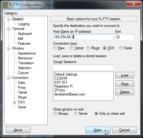
- To talk to the RPi using SSH from the PC, get PuTTY and install it.
- Run PuTTY and SSH into the RPi at address 169.254.68.2:
![]()
- Login to the RPi using the account "pi" and the password "raspberry".
SSH Over the Wireless Network
You can do everything over the wired Ethernet, but I prefer the convenience of using my local wireless network.
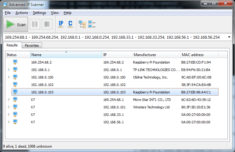
- To allow the RPi to access the local wireless network, open the /etc/wpa_supplicant/wpa_supplicant.conf file and append the following lines:
network={ ssid="XESS" psk="whatever_my_wireless_password_is" } - Reboot the RPi and then look for the wireless connection using something like Advanced IP Scanner:
![]()
- Now disconnect the Ethernet cable and use PuTTY to SSH into the RPi over the wireless network using the IP address found in the last step (192.168.0.103).
Enable File Sharing
Sharing files between my PC and the RPi lets me use a familiar editor to write source that can then be dropped onto the RPi.
- To share files between the RPi and the PC, install Samba on the RPi like so:
$ sudo apt-get update $ sudo apt-get install samba $ sudo apt-get install samba-common-bin - Edit the /etc/samba/smb.conf file and add the following at the bottom:
- Start the Samba server running on the RPi:
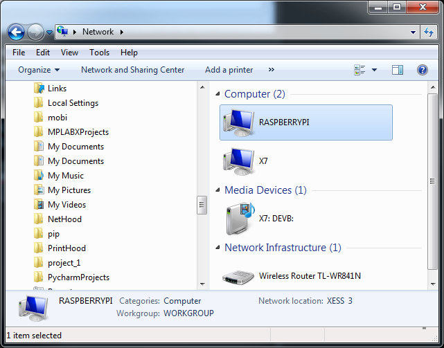
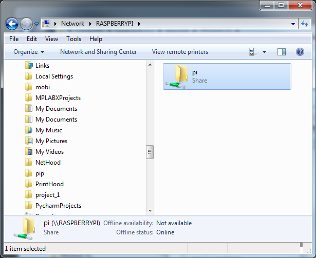
- Open the Network window on the PC. The RPi should be visible there:
![]()
- Double-click the RASPBERRYPI icon and the shared directory will appear. Files can be transferred between the PC and RPi there:
![]()
[pi]
path=/home/pi
writeable = yes
browseable = yes
only guest = no
create mask = 0777
directory mask = 0777
public = yes
Also, change the name of the workgroup to whatever is being used for the Windows PC:workgroup = XESS
sudo service smbd start
Reconfigure the RPi
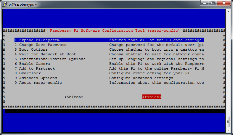
Before the RPi can be used to program the CAT Board FPGA, a few of its configuration settings need to be adjusted:
- On the RPi, type the command:
sudo raspi-config
- In the initial screen that appears, select option 1 for expanding the linux partition. (The stock Raspbian OS image creates a 4GB partition. This won't be enough to compile the FPGA tools. Believe me, I tried.)
![]() As an alternative, you can also use the command-line version to do the same thing:
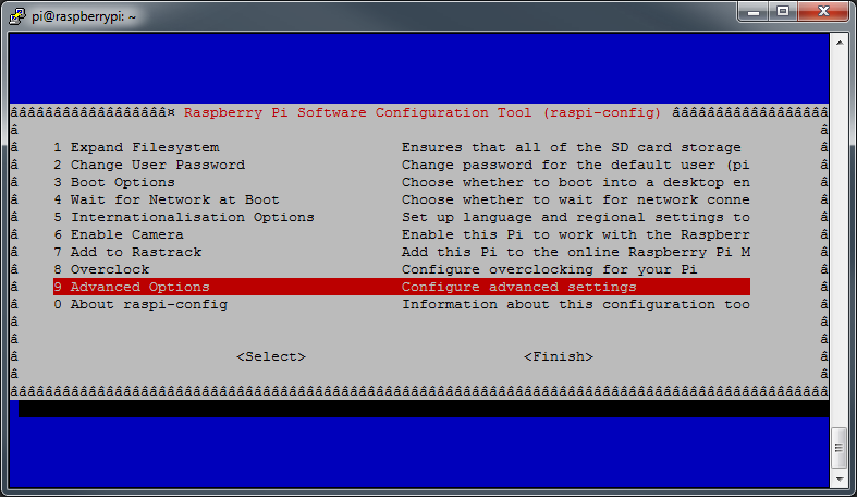
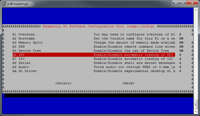
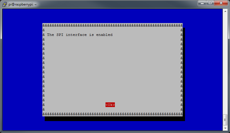
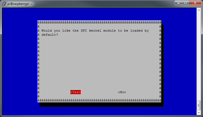
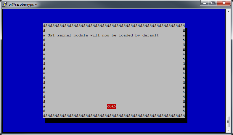
As an alternative, you can also use the command-line version to do the same thing:sudo raspi-config --expand-rootfs - Communicating with the CAT Board also requires the use of the RPi's hardware SPI port. That is enabled using the following screens:
![]()
![]()
![]()
![]()
![]()
![]()
- Finally, close raspi-config and reboot the RPi to let the changes take effect.
![]()
Install the FPGA Software Tools
There are five software packages needed for compiling bitstreams for the Lattice iCE40 HX FPGA on the CAT Board:
- First, install some precompiled packages that the FPGA tools depend upon:
all_deps="build-essential clang bison flex libftdi-dev libreadline-dev gawk tcl-dev libffi-dev git mercurial graphviz xdot pkg-config python3" sudo apt-get install $all_deps - Build the icestorm tools that create bitstreams for the iCE40 FPGAs:
cd /opt sudo git clone https://github.com/cliffordwolf/icestorm.git cd icestorm sudo make sudo make install - Build the arachne-pnr tool that places and routes the circuitry with the FPGA:
cd /opt sudo git clone https://github.com/cseed/arachne-pnr.git cd arachne-pnr sudo make sudo make install - Build the Icarus tool that simulates the operation of the circuitry described by HDL source files. (This takes a long time. Icarus is used to test the functions of the yosys tool that's built next. If you trust the build process and don't want to run the tests, then you don't need Icarus.)
cd /opt sudo apt-get install autoconf gperf sudo git clone git://github.com/steveicarus/iverilog.git cd iverilog sudo sh autoconf.sh sudo ./configure sudo make sudo make install - Build the yosys tool that synthesizes logic circuitry from Verilog source files:
cd /opt sudo git clone https://github.com/cliffordwolf/yosys.git cd yosys sudo make config-clang sudo make sudo make test sudo make install - Install the litterbox tool that transfers a bitstream file from the RPi into the FPGA on the CAT Board:
sudo pip install litterbox
Create the Blinky Design
Finally, I've reached the point where the blinky is designed. The blinky only does one thing: it blinks an LED on and off once each second.
The CAT Board has four LEDs and a 100 MHz clock connected to the iCE40 FPGA. So all I need is a counter driven by the clock that increments to 50,000,000 and then toggles one of the LEDs in a repeated fashion. Here's some Verilog code I stored in the blinky.v file that does that:
module blinky(clk_i, led_o);

input   clk_i; // Clock input.
output  led_o; // LED output.

reg     [25:0] cnt; // Counter with max count of 2**26=67,108,864.
reg     tgl; // Toggle flag for driving LED.

assign led_o = tgl; // Connect LED to toggle flag.

always @ (posedge clk_i) // Do this on every rising edge of the clock.
begin
    if (cnt == 50000000-1) // Has the counter reached its limit?
    begin
        tgl = !tgl; // Flip the LED from OFF-to-ON or ON-to-OFF.
        cnt = 0;    // Reset the counter.
    end
    else // Keep incrementing counter until it reaches its limit.
        cnt = cnt + 1;
end

endmodule
In addition to the Verilog code, I need a way to tell the FPGA tools what pins of the FPGA are connected to the clock signal (pin C8) and the LED (LED1 is attached to pin A9). That information is stored in a pin constraints file called blinky.pcf:set_io clk_i C8 set_io led_o A9
Compile the Blinky Design
The start of the FPGA compilation process begins with yosys. It parses the Verilog source and synthesizes a set of interconnected logic gates that implement the desired function. The gates and their interconnections are stored in a BLIF (Berkeley Logic Interchange Format) file.yosys -p 'synth_ice40 -top blinky -blif blinky.blif' blinky.vThen the BLIF and pin constraints files are sent to arachne-pnr which maps the gates into the logic array of the iCE40 HX8K FPGA and programs the switches in the connection matrix to connect the gates to each other and to the requested I/O pins.arachne-pnr -d 8k -o blinky.asc -p blinky.pcf blinky.blifThe blinky.asc file contains an ASCII representation of the settings for all the programming bits in the FPGA. The icepack tool turns this into a bitstream file with a binary format that can be downloaded into the FPGA.icepack blinky.asc blinky.bin
Load the Blinky Bitstream Into the FPGA
The bitstream file is loaded into the FPGA with the litterbox tool:
sudo litterbox -c blinky.binAfter the FPGA configuration is complete, LED1 on the CAT Board will start to blink on and off once every second.
The bitstream can also be stored in the serial flash so the FPGA will start to blink whenever power is applied to the CAT Board:
sudo litterbox -p blinky.binHere's a video that shows the compilation and downloading steps for the blinky design: -
CAT Board: All On It's Own
04/27/2016 at 02:51 • 2 commentsOne of the reasons for respinning the CAT Board PCB was to get the SPI flash chip connected correctly to the Lattice FPGA. The flash+FPGA+Raspberry Pi interconnection is complicated because it has to operate in three different modes:
- During development or when the FPGA is being used dynamically, the RPi has to be able to load a configuration bitstream into the FPGA.
- After development is completed, the RPi may want to store the finished FPGA bitstream into the flash.
- When the CAT Board is used stand-alone or when the FPGA performs some fixed function for the RPi, the FPGA has to be able to configure itself upon powerup with the bitstream stored in the flash.
All three modes have to share a single SPI bus between all the devices while using a minimum of RPi GPIO signals and extra circuitry.
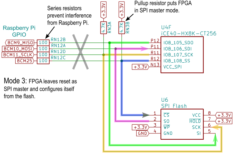
Mode 3 is the easiest: when the FPGA powers up (or is reset), it checks to see if the SPI CS line is pulled high and, if so, becomes an SPI master and reads its configuration bitstream from the flash. The RPi GPIO signals are hidden behind the series resistors and can't interfere.
![]()
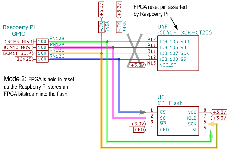
Mode 2 is slightly more difficult. When the RPi is storing a bitstream by sending it to the flash chip's SI input, the SPI CS line is pulled low. But that also enables the SPI interface of the FPGA which could lead to interference if the FPGA's SDO output becomes active. To prevent this, the RPi asserts the reset pin of the FPGA so its SPI port can't turn on. Problem solved.
![]()
Mode 1 is the most difficult. The RPi pulls the SPI CS line low as it removes the reset from the FPGA. This places the FPGA in slave mode so the RPi can send a bitstream to the FPGA's SPI port. But this also enables the flash chip's SPI port, which means the flash's SO output could interfere with the bitstream data. Unfortunately, there's no reset pin on the flash to keep it quiet. However, the flash does have a deep power-down mode that is entered by sending a specific command to the flash. Once in this state, it will not respond to anything until it receives another specific command to wake up. The RPi can then transfer the bitstream to the FPGA. During the transfer, there's no chance the wake-up command will be sent accidentally to the flash's SI input because 1) neither the RPi or FPGA will be driving that signal line during the configuration process, and 2) the flash only executes a command once its CS input goes high but the SPI CS line is held low for the entire duration of the bitstream transfer. So the flash will stay quiet and the RPi can send the bitstream to the FPGA in peace.
![]()
Another complication of the shared SPI bus is that the roles of the RPi's MOSI and MISO pins are reversed in modes 1 and 2. In mode 1, the RPI's MOSI output pin drives the SDI input of the FPGA and the FPGA's SDO output drives the RPI's MISO input. That allows the hardware SPI port of the RPi to be used for the SPI transactions. But in mode 2, the RPi's MOSI pin acts as an input to receive data from the flash's SO output and the RPI's MISO pin has to drive the SI input pin of the flash. That precludes the use of the RPI's SPI hardware and the SPI transfers to/from the flash have to be done using bit banging.
I searched for a ready-made SPI bit-banger program but nothing great popped up. So I just wrote one in Python using the RPi.GPIO library. It consists of a class for handling individual pin I/O, another class for SPI transactions, and a final class that handles most of the commands for the serial flash chip.
To test the code, I first tried the command to read the device ID from the flash. The manufacturer and device IDs should have been 0x1F and 0x8401, respectively. Instead, I got 0xFF and 0xFFFF. That's OK; nothing ever works the first time.
I probed with an oscilloscope to make sure the RPi was driving the correct pins of the flash. No problem there except that the SO pin was always high (naturally).
Next, I pulled out my old HP LogicDart and sampled the waveforms on the CS, SCK and SI pins. Once again, no problems: the clock edge was occurring in the correct place and the command byte was what it should be.
Possibly the chip was fried, so I replaced it. Same result.
Maybe something else on the board was holding the SO pin of the flash high. I desoldered the pin from the PCB pad and probed it directly. Same result.
Then I thought: "What if the flash is in the deep power-down mode? Then it would never react to the device ID command." The datasheet says the flash is not supposed to be in deep power-down mode unless it is explicitly commanded to do so, but I didn't have any better ideas so I sent the command to wake the chip before asking for the ID...
Success!
In retrospect, it's obvious what was happening. When the CAT Board is attached to the RPi and power is first applied, the FPGA comes up in SPI master mode and tries to read its configuration bitstream from the flash chip. Whether it finds a valid bitstream or not, the last thing the FPGA does is send the deep power-down command to the flash to save power. So by the time the RPi was fully booted and I ran my bit-bang code, the flash was already asleep.
Once that mystery was solved, the rest of the commands for erasing, programming and verifying the flash worked right away. Then it was just a matter of storing a bitstream into the flash and seeing if the FPGA would configure itself without the aid of the RPi. The following video demonstrates this:
CAT Board
The CAT Board is part of a Raspberry Pi-based hand-held FPGA programming system.

 As an alternative, you can also use the command-line version to do the same thing: