 David Scholten
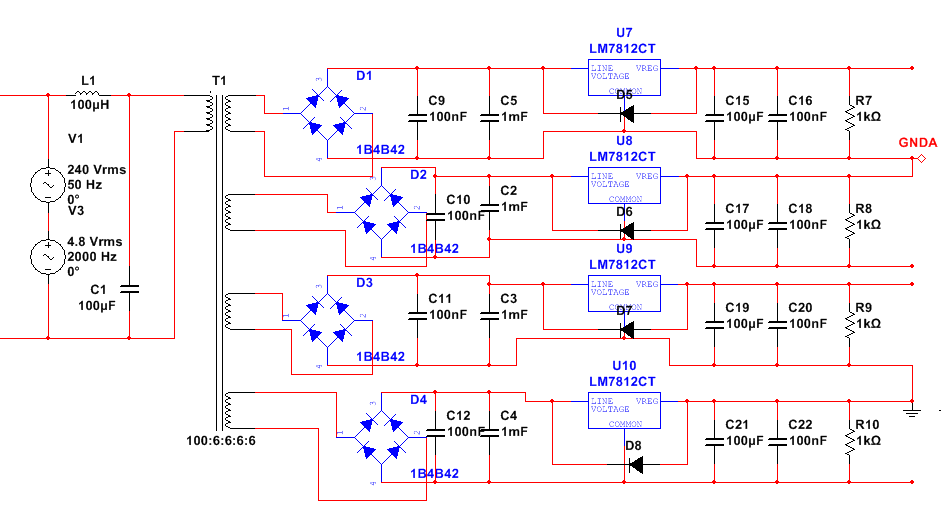
Finally had some time to get to work on the circuit design! First off is a tentative power supply with an input filter to ensure harmonics from the grid are minimised:
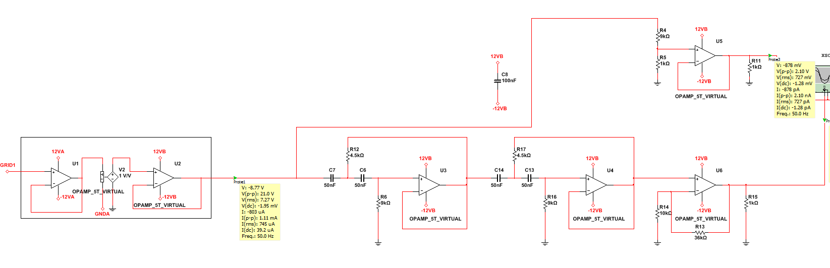
Taken from a resistive divider on the grid side, voltage measurements are then passed through an isolation amplifier to some op-amp stages for signal processing and buffering:
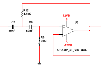
A standard active 2nd-order high pass op-amp filter:
Having some fun with filters and nifty AC analysis functions in Multisim 12:
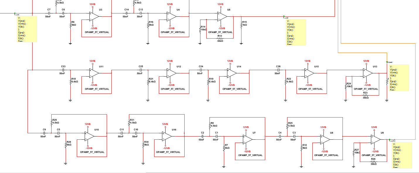
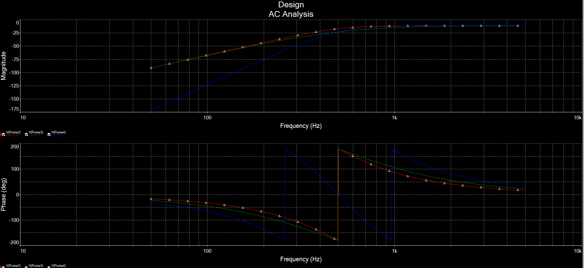
Starting to have some fun with this after all!
Discussions
Become a Hackaday.io Member
Create an account to leave a comment. Already have an account? Log In.