 David Scholten
After an afternoon pretending that I know how to design third order op-amp filters, I settled on the following for the harmonics filter with the help of a web tool (http://sim.okawa-denshi.jp/en/Fkeisan.htm):
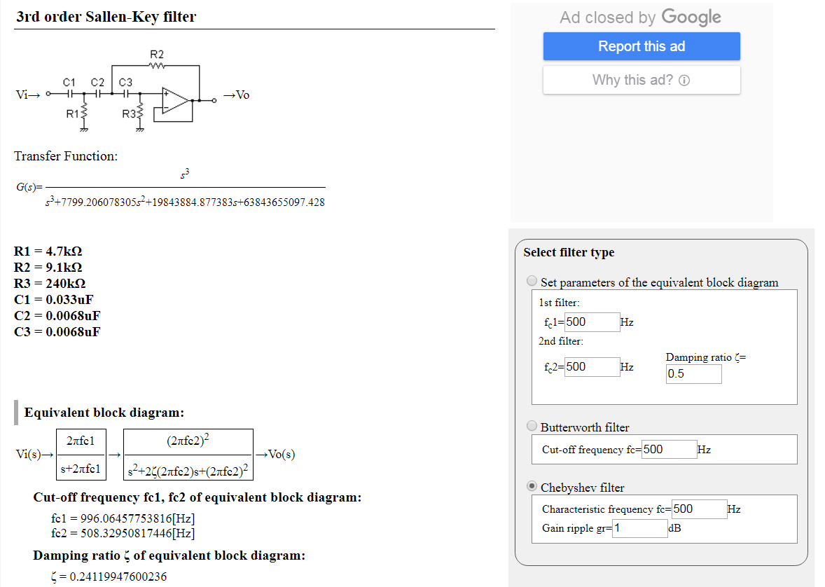
This tool helped with the design of the following:
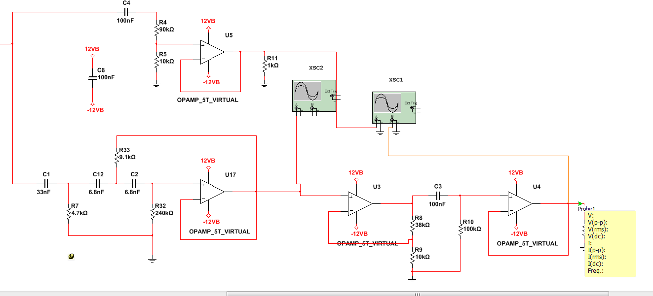
Ignoring the op amp at the top, the bottom three perform the following functions (in order):
-->Third order high pass filter -->Voltage gain -->Offset removal and buffer.
The third order filter is a Sallen-key type set up as a Chebyshev style with a cutoff frequency of 500Hz and a 1dB oscillation at the higher frequencies:
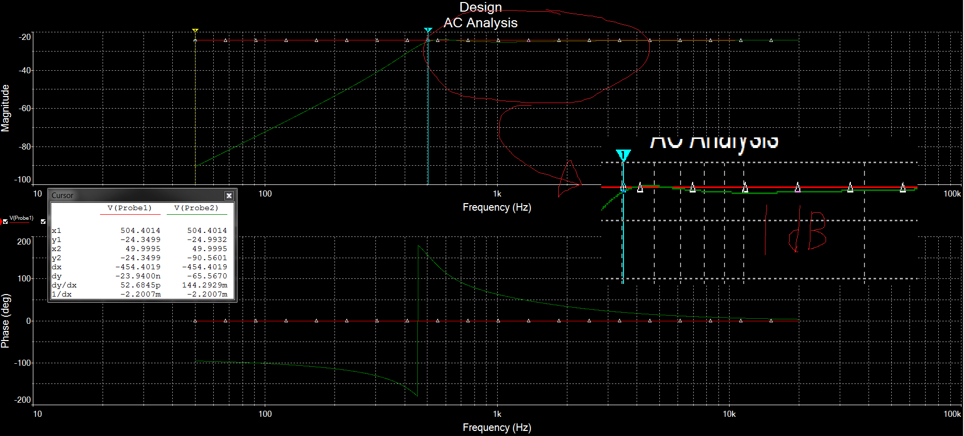
Now, with both the main signal of the grid and the harmonics (500Hz) set to the correct 1Vpp levels for sound card audio (assuming a maximum grid harmonic distortion of 5%), the two output signals look as followed on a virtual scope:

Within the actual "harmonics" output itself, the grid rejection of the 50Hz signal is -60dB (a one thousandth), but as the fundamental component is 20 times the maximum harmonic level, the practical 50Hz signal in the harmonics signal will be 1/50 (i.e. -24dB) compared with the harmonics waveform.
Discussions
Become a Hackaday.io Member
Create an account to leave a comment. Already have an account? Log In.