It took me longer than I expected, but I finally had a few evenings of spare time to populate new board with components and do a bit of programming. Here is quick update of status:
New PCB
Design in Eagle
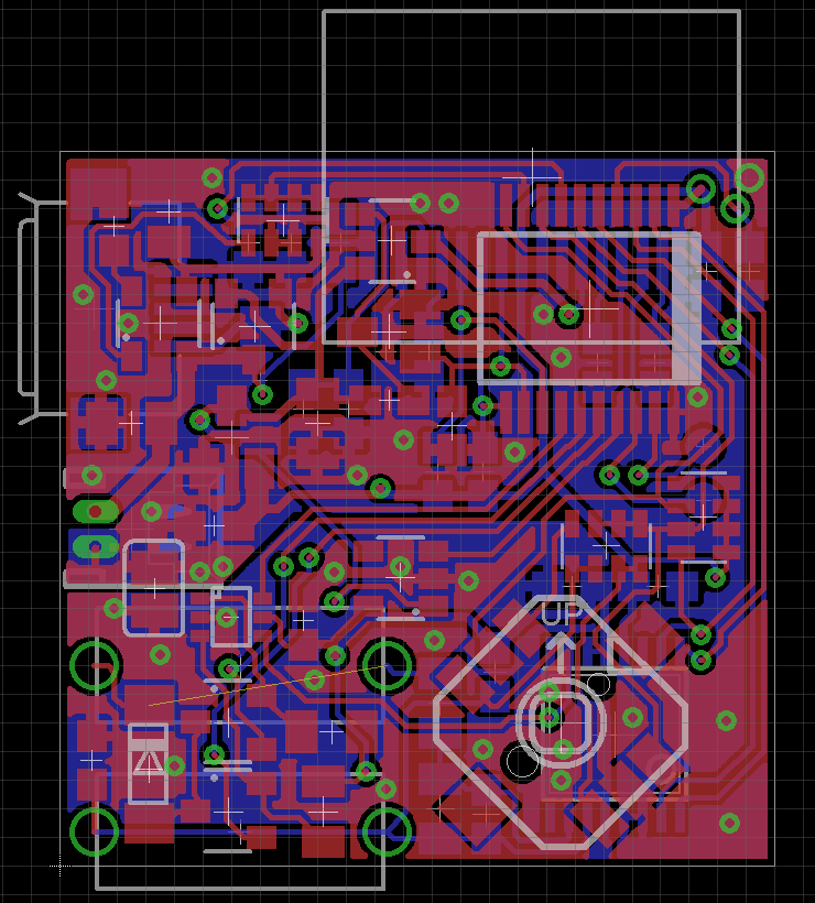
and in reality, manufactured by cheap local manufacturer it looks like this
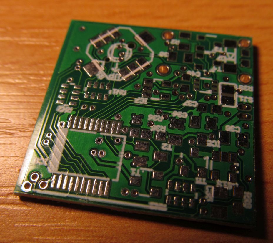
The silkscreen isn't perfect for such as tiny board, but I don't care that much. The most significant difference to previous board is change of main ADC from MCP3424 to ADS1120. I had to free up four pins for full SPI interface, but the previous design was quite constrained in this aspect - so I opted to connect the joystick into resistor network and sense the joystick position by ADC. I left the original schematics on github as well as there is new one to compare.
The new ADC works as expected and in fact, everything went flawless on first try. I reused "testbed" from previous hardware revision to continue with development
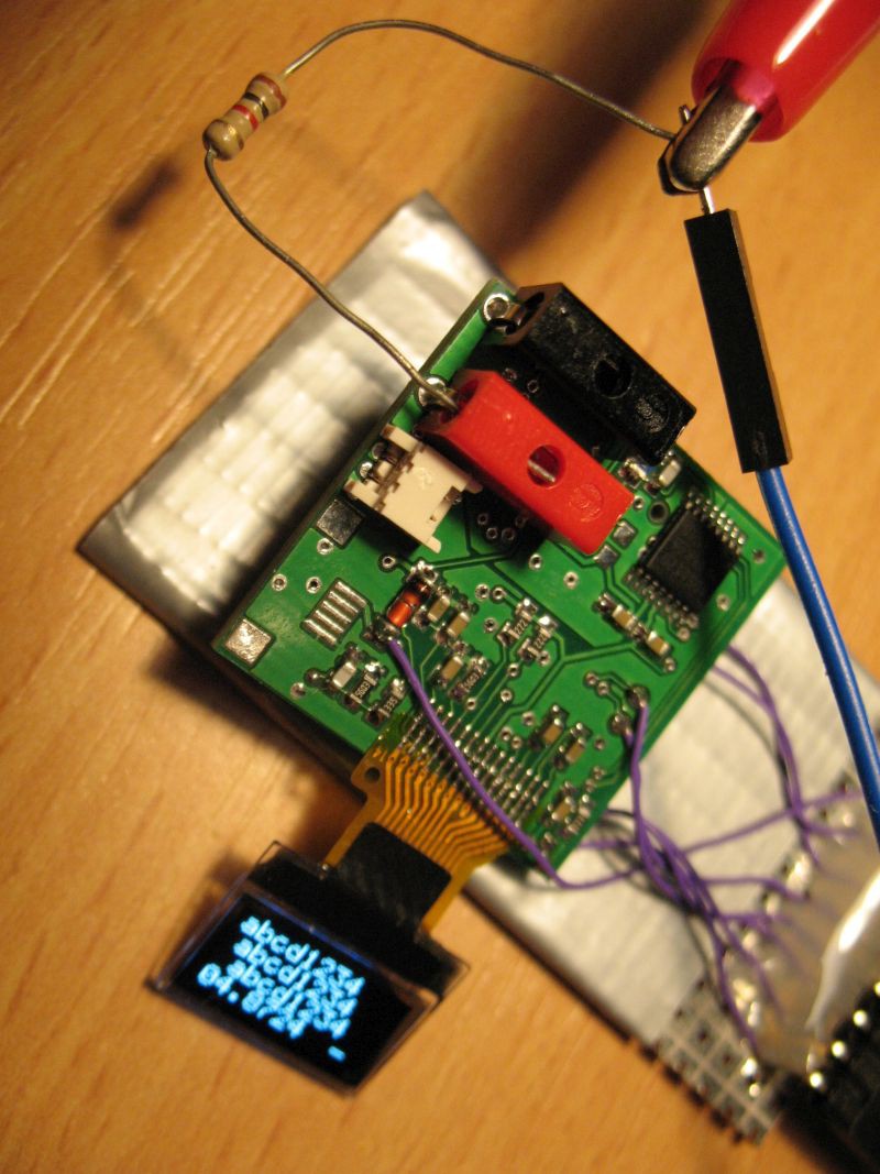
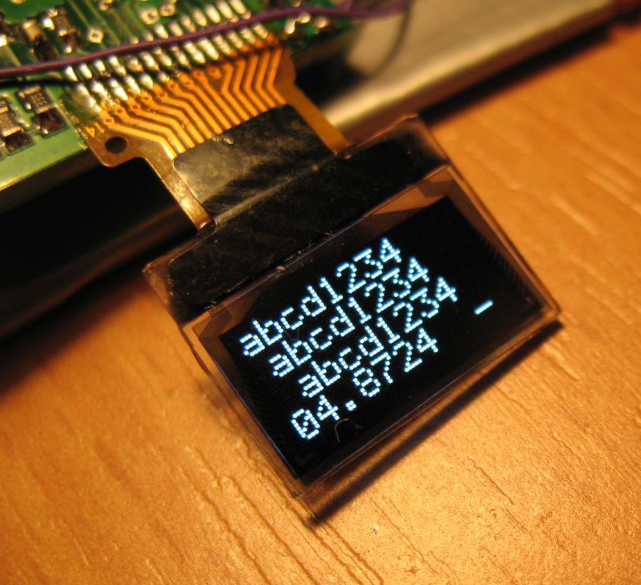
Firmware
I'm writing the firmware mostly on my main Linux machine, but I don't forget on Windows users too. I'm using MPLABX suite from Microchip along with their XC8 compiler as well as SDCC. Compilation from command line without MPLABX should be easy.
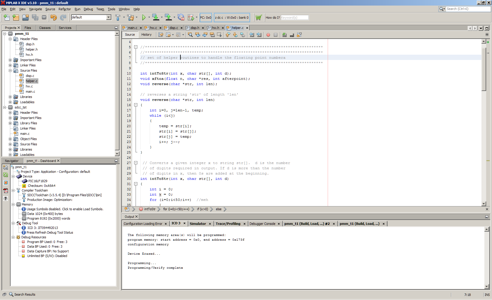
For now, I prepared basic skeleton of firmware, with ADC and display routines working with both XC8 and SDCC compilers, so I can start with more interesting parts. The firmware is available at github.
 jaromir.sukuba
Discussions
Become a Hackaday.io Member
Create an account to leave a comment. Already have an account? Log In.
Cool, never seen flat-cable soldered like that by a hobbiest, was it difficult?
Are you sure? yes | no
Not at all. In fact, it is quite easy provided you have average soldering iron and flux, but this is necessary for other SMD parts anyway.
Working with the flat cable isn't that that hard and it isn't as fragile as it may look. This particular piece was already used on my first prototype, I put it down and resoldered on new prototype with no problem.
Are you sure? yes | no