jaromir.sukuba
-
Resume
12/27/2015 at 22:57 • 0 commentsStarting this day, I'm calling this project finished and ready for #The Square Inch Project
I believe it met the goals I set up in my first thoughts and after having problems with hardware and totally failing with first ADC and hardware redesign I managed to finish it into satisfactory shape, to point out a few project logs from total 19, not including this one.
I also hope I left here enough of material for anyone to replicate hardware, software and perform calibration, so there is knowledge base to fix bugs or fork of new design.
Here is a few things I'd consider when doing micro progmeter v2:
- fix leakage of analog switches for resistance measurement.
Leakage of BSS84 transistors causes non-zero voltage (~ 0,01V) on voltage measurement range with measurements probes floating. Once shorted, it shows 0,000V, as expected. This is more like cosmetic problem, IMHO - but one could hopefully cure it by connecting common point of R6 and R7 (refer to schematics on github) not into analog 3,3V node, but into D electrode of another PFET switch with BSS84. This point should be grounded via appropriate resistor, too high value would cause poor leakage masking, too low value would cause too high current draw. Something like 1-50kOhm (to be tested) should do the job. The third transistor should be kept closed (G on high potential) when performing voltage measurements.
- find better MCU, this one is really FLASH starving.
Though PIC16F1829 or 1509 are my favourites when it comes to small projects, I seriously underestimated how much FLASH hungry the floating point routines are. There are options like STM32F031, but I like Microchip parts and this project was aimed at pointing out other than the most mainstream paths in field of microcontroller based designs, so I'd stick with this manufacturer.
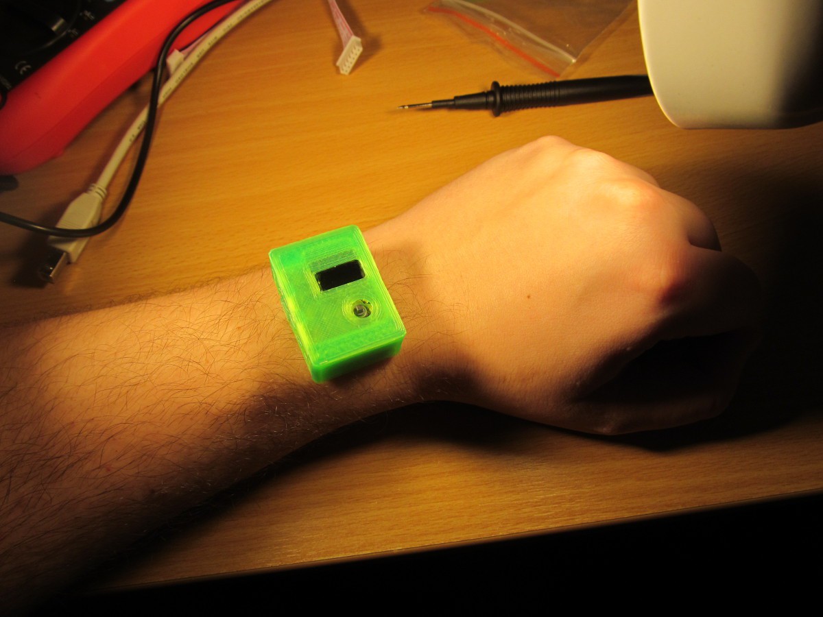
- smart watches?
Honestly, I hate the hype around smart watches. Smart watches are here for a long time, even the DIY versions, so it is basically nothing new. I was hanging out with my friends and showing them this project, somebody pointed out its remote similarity with watches
![]()
DMM watches, pretty pointless, but cool.
-
Video, twice
12/24/2015 at 22:22 • 2 commentsThis video captures micro progmeter in action
I'm measuring 1,5V AA and 9V 6F22 battery, then 1kOhm and 680kOhm resistors, then I'm demonstrating calculation capability of device.
Second video is the reason why I started the PIC16 arduino programmer project - to give open-sourced and available programmer alternative to micro progmeter.
Not exactly lightning fast, but it works.
-
Want to build one? (part three, calibration)
12/23/2015 at 10:33 • 2 commentsSo, now I'm assuming you have working hardware and set-up software to build the firmware for micro progmeter.
Because progmater doesn't have dedicated programming header (due to space constraints), solder extension wires for programmer lines (GND, VDD, MCLR, PGD, PGC), as I did it here
![]()
You may solder it temporarily, just for sake of programming the PIC micro, or leave it permanently for firmware updates.
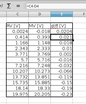
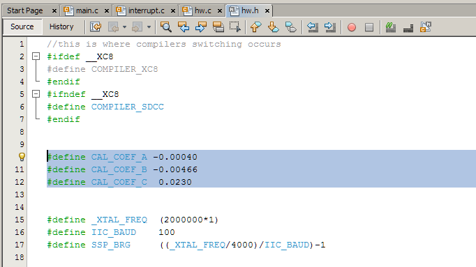
Locate file hw.h and look for coefficients CAL_COEF_A, CAL_COEF_B and CAL_COEF_C. Those are coefficients of quadratic equation used to correct not very initially accurate, but hopefully stable and repeatable voltmeter part of micro progmeter.
Set all coefficients to 0.0, so no correction occurs and device displays raw measured value. Connect micro progmeter to laboratory power supply, increase voltage and check with ecternal voltmeter, ideally something better than cheap 3,5 digit DMM. You may find out that zero has some offset and higher voltage do have increasing measurement error. Take a dozen of values (the more the better, but there is no point having more than two dozens of them) between 0 and 20V, put into your favorite spreadsheet editor and it may look like this
First column is real value, followed by measured value and voltage difference. This is the difference we need to cancel out.
![]()
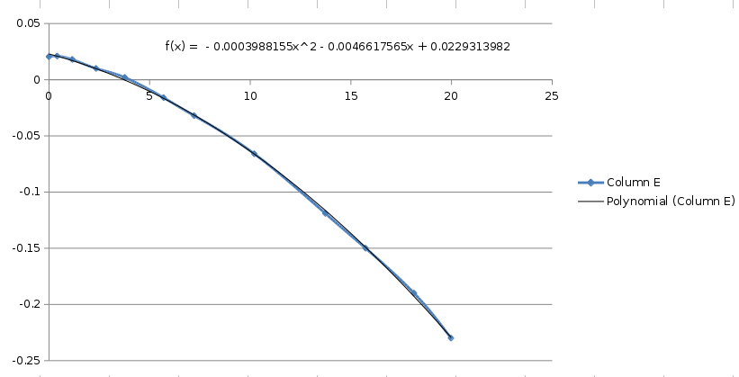
Insert a chart of difference versus real value and add quadratic approximation of it (in Excel or similar - left click on graph, add trend line, polynomial, 2nd order, show in graph). You may need to adjust text formatting to show more decimal places of quadratic coefficients - and there you have it, CAL_COEF_A, CAL_COEF_B and CAL_COEF_C.
So now we have calibration curve and calibration coefficients, enter it into sources![]()
recomplie and upload. Your progmeter should now be fairly precise.![]()
If you don't have adjustable laboratory power supply, you may use various power sources around, like 0V (shorted input terminals), 1,5V (AA battery), 4V (Li-Ion), 5V (USB), 9V (6F22 battery), 12V (power supplies to various electronics or car battery, more like 14V) and 19V (laptop power supply) to perform the calibration. Always calibrate against another good voltmeter!
For my calibration I used UT-61E DMM along with Matrix MPS-3003D (generic chinese shit sold under different labels) power supply. Both cheap, but sufficient for me.
Finding out calibration coefficients via Excel isn't the most elegant solution, but simple, accessible and good enough for one-off task. You may use anything, from Matlab to manual calculation via least squares method, depending on your creativity and skill.
-
Want to build one? (part two, software)
12/22/2015 at 12:27 • 0 commentsNow you may want to build the sources using MPLABX IDE and SDCC or XC8 compilers under Linux or Windows. Here is how:
Using XC8 compiler
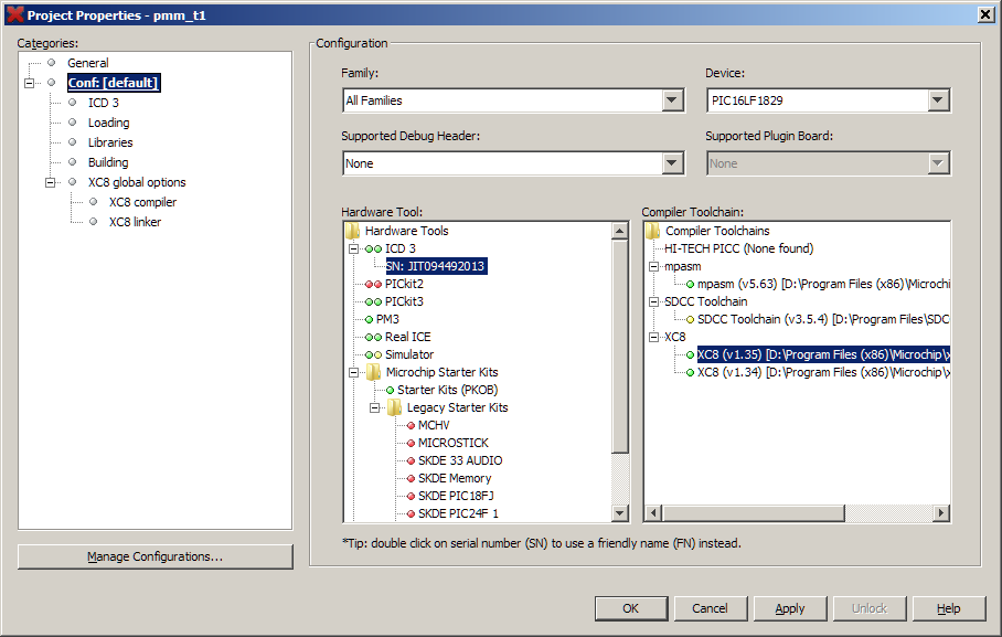
Download MPLABX IDE, I did my development on v 3.15 and 3.10. If you want to build using XC8, download it here - I did my development on v 1.35. Then, download sources from here, open project in MPLABX and you should be ready to build. Check project properties (right click on project name->Properties)
![]()
and if everything is OK, hit "clean and build" project icon.
![]()
After a few seconds, you should be able to see successful build log
![]()
If you have ICD3 or PicKit3 connected (chinese clones work good), you should be able to program the target PIC16LF1829 in micro progmeter device, just hit "program" icon
![]()
And programming should run as expected. If do not happen to have ICD3 or PicKit3 programmers, you can use any other programmer, like this one and use build hex file found in "...path_to_project...\pmm_t1.X\dist\default\production", named like "pmm_t1.X.production.hex".
The same procedure applies under Linux. I tested it under Linux Mint 17.2 64-bit. Hint: if your compiler installer fails to start, use "--mode text" switch, like
# sudo ./xc8-v1.35-full-install-linux-installer.run --mode textFor installing IDE, you may refer to help, but on Linux Mint 17.2 everything went flawless.
Now you have built micro progmeter sources using MPLABX and XC8 compiler
Using SDCC compiler
If you prefer open-sourced compiler, you can use SDCC, here is how:
Download MPLABX IDE, I did my development on v 3.15 and 3.10. If you want to build using XC8, download it here - I did my development on v 1.35. Download SDCC binary for Windows or Linux and gputils along with SDCC plugin for MPLABX.
After installing MPLABX, SDCC and gputils packages, open MPLABX, go to Tools->Plugins and install SDCC plugin
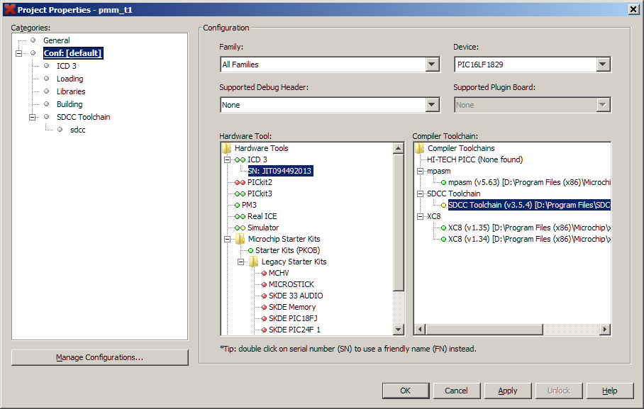
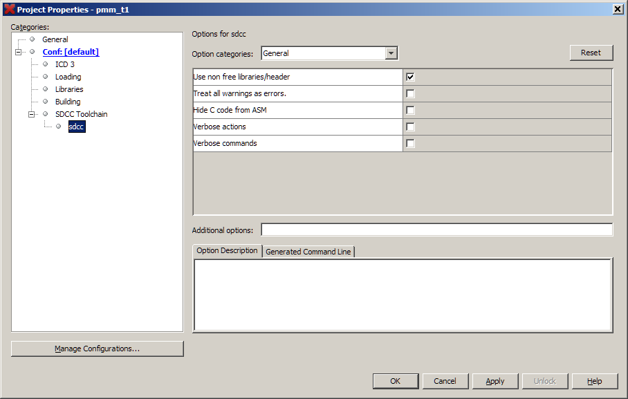
After MPLABX performs restart, open project and make sure SDCC is properly configured in project properties![]()
![]()
![]()
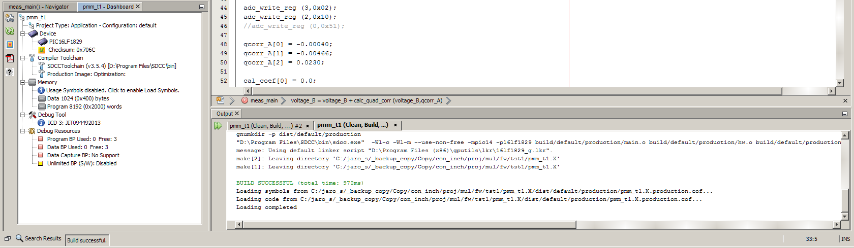
hit "clean and build" project icon
![]()
and build should run as expected
![]()
If you have ICD3 or PicKit3 connected (chinese clones work good), you should be able to program the target PIC16LF1829 in micro progmeter device, just hit "program" icon
![]()
And programming should run as expected. If do not happen to have ICD3 or PicKit3 programmers, you can use any other programmer, like this one and use build hex file found in "...path_to_project...\pmm_t1.X\dist\default\production", named like "pmm_t1.X.production.hex".
The same procedure applies under Linux. I tested it under Linux Mint 17.2 64-bitTo get support for newst PIC micros, you may want to install gputils from source, it is relatively simple
$ svn co https://gputils.svn.sourceforge.net/svnroot/gputils/trunk/gputils gputils_svn
$ cd gputils_svn/
$ ./configure
$ sudo make install
Regarding SDCC - if you donwload actual release version of SDCC 3.5.0, you may happen to stumble across "GLIBC 3.4.20" problem. Please, download some newer snapshot, I used 3.5.1 #9263
Now you have built micro progmeter sources using MPLABX and SDCC compiler
Without using MPLABX
It should be possible to build the sources without MPLABX. There is makefile inside the project directory and it should be usable directly from command line. Honestly, I didn't test this one yet.
-
Want to build one? (part one, hardware)
12/22/2015 at 10:47 • 0 commentsPCB and components
Order PCB from your favorite supplies. You have Eagle PCB design files (to be opened in version 6 or higher) available here or gerber manufacturing data (generated by iteadstudio CAM file) available here.
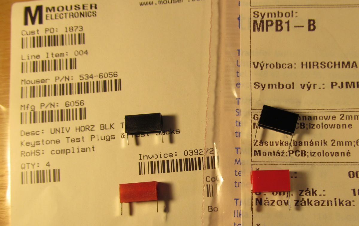
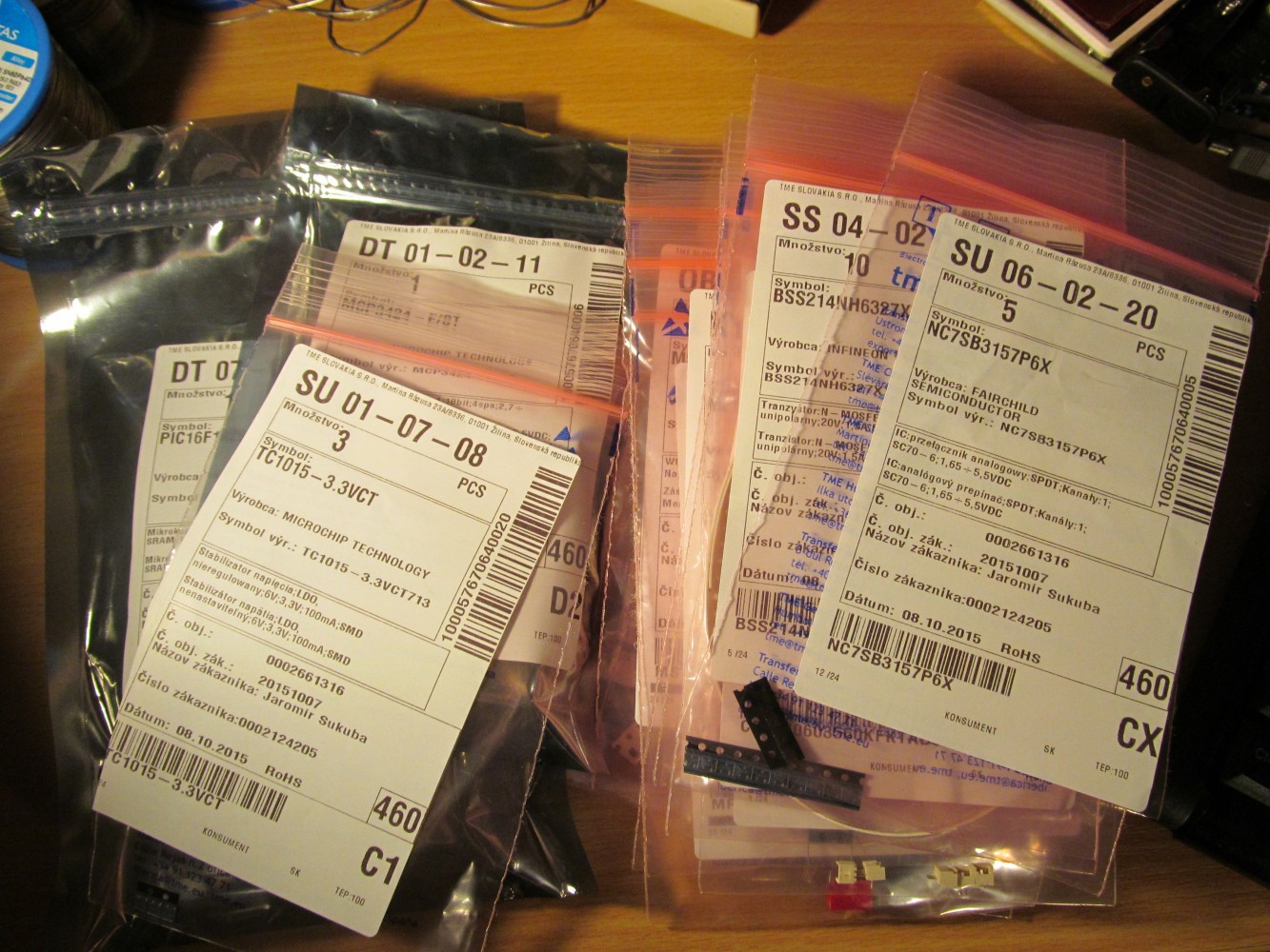
Before the PCB arrives, you have plenty of time to order components according to this BOM. Passive components are jelly-bean parts and should be available anywhere, I bought them mostly at TME. Most of the resistors are 0603 parts, but some are 0805 sized - all those are in "sensitive" places, where absolute accuracy and temperature coefficient plays role, and better resistors make slightly better progmeter. I used 0,1% 25ppm parts for 6K8 and 470k from TME, and 10M and 1M from Mouser.
I bought PIC18LF1829 at Mouser, but it is available at Digi-key or elsewhere, as well as ADS1120 here and here. Analog switch NC7SB3157 is from TME, but available at Mouser too. TC1015 is cheap at TME, but Mouser keeps them too. The same goes for MCP1702 and second source. MCP73831 is etting jelly-bean part, like here and here and elsewhere.
Battery connector is type MX-53047-021, available at TME as usual, but Mouser is OK too. 2mm banana plugs are good at TME, but Mouser keeps similar one and this one. I have to admit the ones from Mouser feel cheaper, though it is actually more expensive.
![]()
BSS214 could be substituted to any low Vgs threshold NFET, IRLML6302 is here just generic low Vgs threshold PFET, BSS84 is available here and here.
Display is generic 0,49" OLED with 64x32 pixels resolution, available at aliexpress, as well as battery. Joystick is from TME, but is seems to be the same as from sparkfun.
![]()
Enclosure
Turn on your favorite 3D printer and while hotend and heatbed is heating up, download STL files for enclosure or play around with source files for Freecad. Notice I'm poor 3D designer, so professionals may be amused.
I printed this one of PLA.![]()
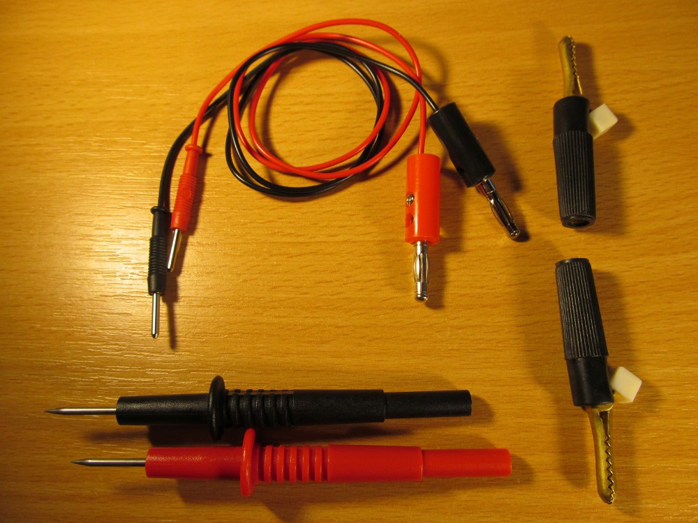
Probes
DMM without probes is not of much use, so here you go. Buy one of those and those (or any other 2mm banana plug), pieces of 0,75mm square cross-section wire, the other end may be of your desire. I used old 4mm banana plugs from junkbox, plus antique 4mm alligator clips and I bought also those test probes too.
So now, hardware is prepared, let's proceed to compiling sources and calibration.![]()
-
Final release
12/22/2015 at 09:45 • 0 commentsSo, here it is. As for now, I'm considering this design to be finished and files on github should cover all you need to build one, perhaps with a little bit of help from local project logs.
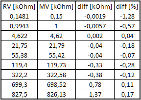
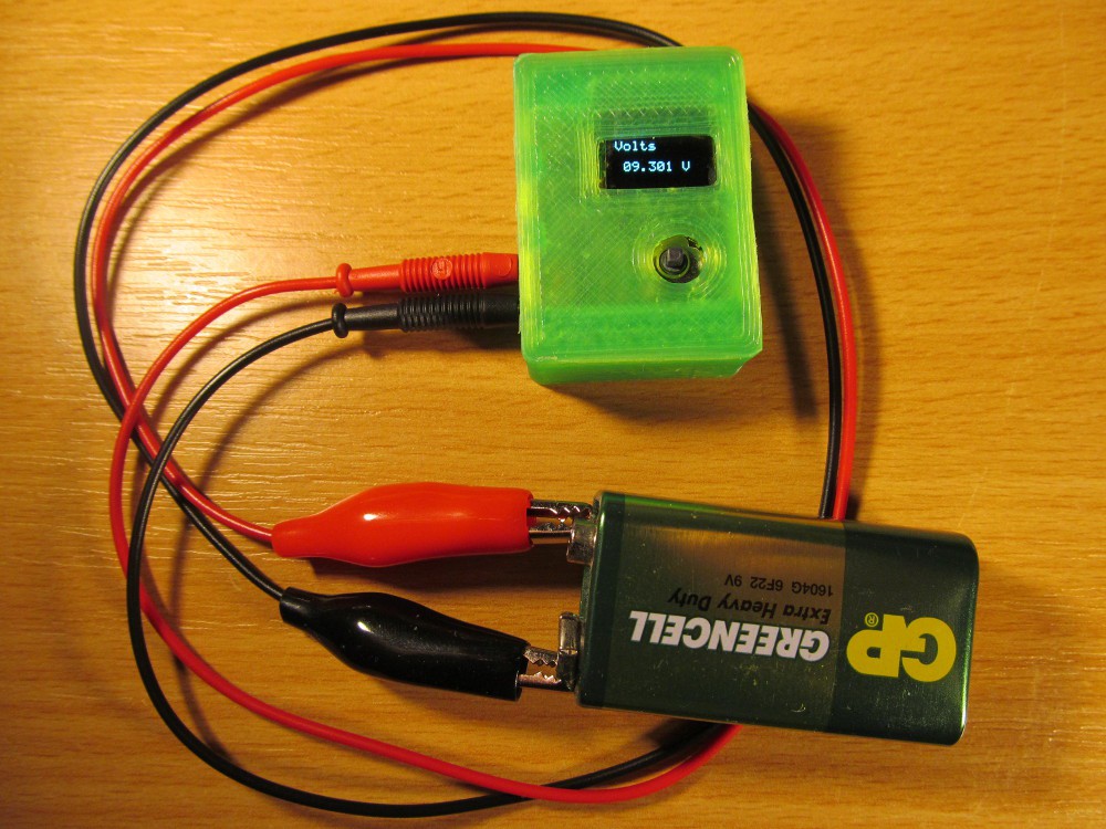
Accuracy verification
After doing proper calibration against higher-spec multimeter than good old trustworthy DT-830 I made accuracy check of my micro progmeter, using laboratory power supply and UT-61E DMM. UT-61E was connected directly to micro-progmeter and measuring the same value. Here is verification table
![]()
where RV is real value (by UT-61E), MV is measured value (by micro progmeter), diff is absolute difference. Diff FS is deviation of full scale value (20V) and diff V is difference of measured value. So, when measuring 1,677V, progmeter displays 1,675V, what is 2mV difference, meaning error approximately 0,01% of full scale or 0,12% of the value.
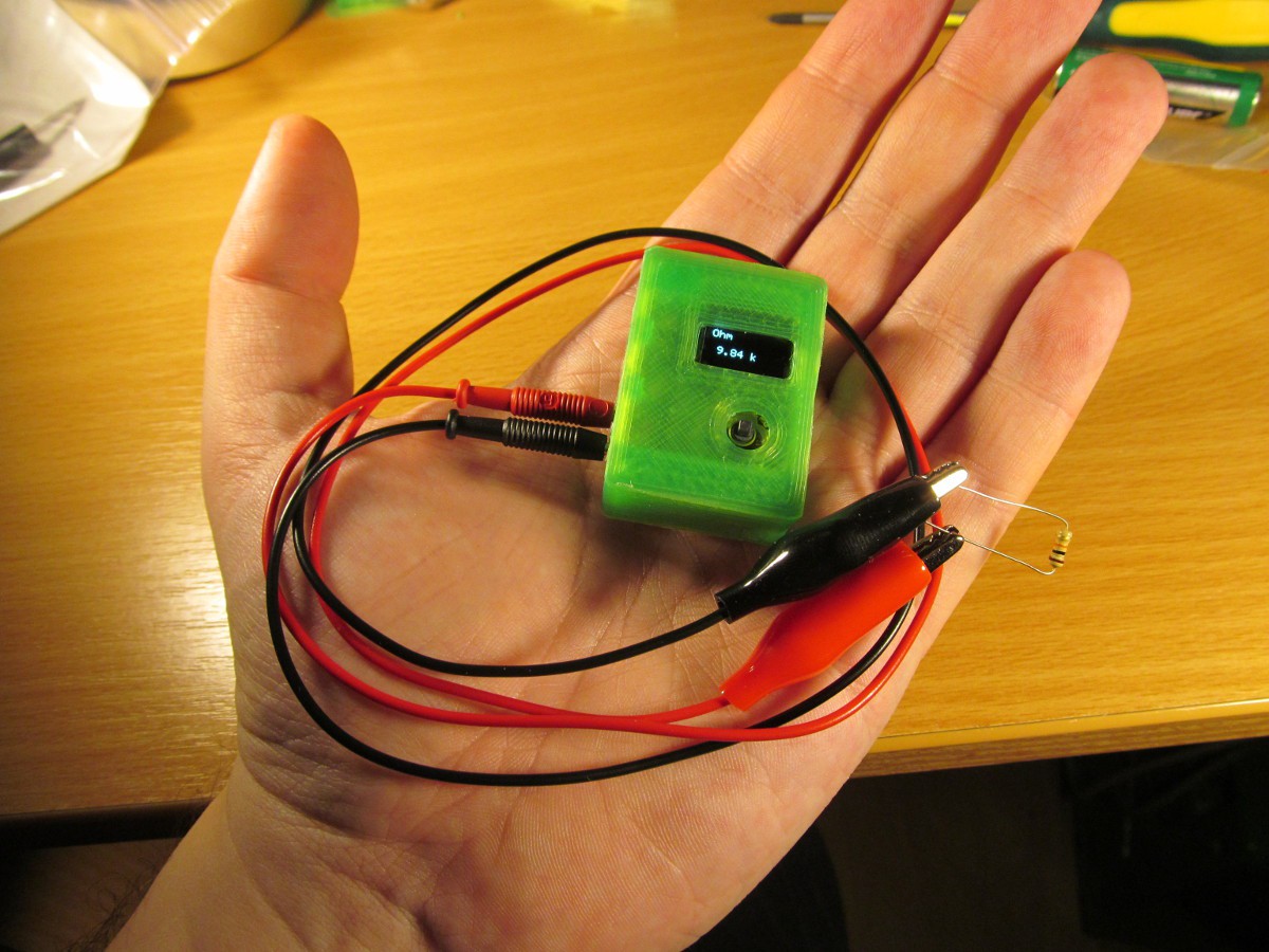
Using bunch of random resistors I verified the resistance measurement too
![]()
As the full range is virtually unlimited, I calculated only measurement error of the value (this is the worse number). At low ranges (few hundreds of ohms and lower), the accuracy is limited by resolution (0,01kOhm = 10Ohm), but even at 150Ohm it is quite respectable. Higher values doesn't suffer from rounding errors, so the performance looks better.
Current consumption
The current consumption of active progmeter is about 4-6mA, depending on amount of illuminated pixels. After turing off it falls to approximately 60uA. I expected something under 5uA, so 60uA is somehow surprising and honestly I'm not sure where it comes from - perhaps display or ADC. I've got a few clues how to find out, but in the meantime progmeter is fully usable. 60uA would deplete 100mAh accumulator in more than two months, so it you use it from time to time it shouldn't matter much.
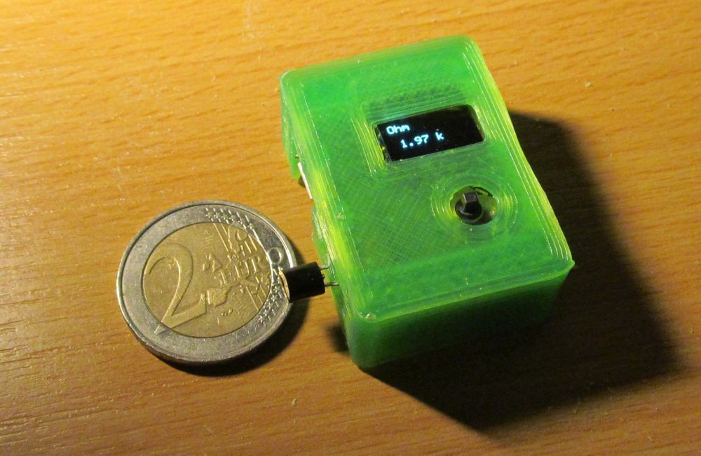
Fool-proofness
The progmeter is fool-proof to some degree. Though measurement range is up to 20V, it survives 30V with no problem. Even at resistance measurement range, it survives 30V of either polarity with no problem whatsoever.
![]()
On the other hand, except of fool-proofness by design up to 30V, it has no other input protection. If you connect it to 230V AC, it will blow up and ruin your day - this is design decision. Proper protection on such as tiny device is somehow problematic and for checking your microcontroller project not needed, anyway.
Resume
Coming back to goals I set up at the beginning of the project, I'd say it works as I intended. Working on this was a great fun and I learned a few new things - like how to set up project for PIC micro using fully open-source tools. The project is made to be as accessible as possible for anybody, disregarding whether you like to use FOSS tools for flexibility or proprietary tools for convenience.
-
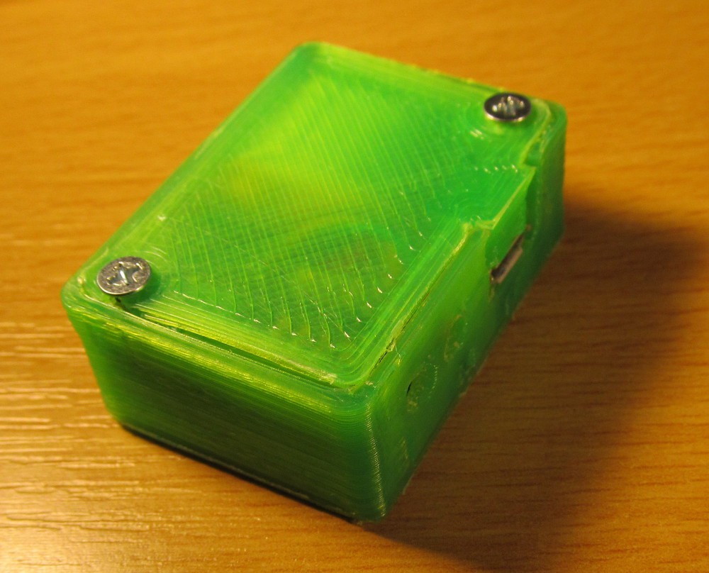
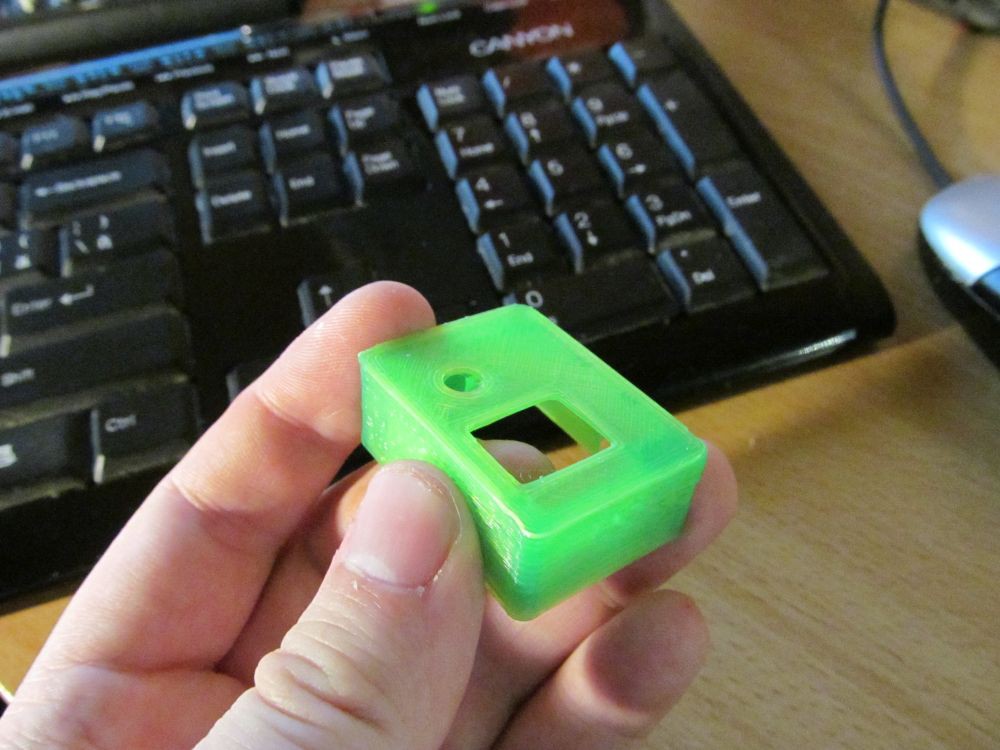
CAT 0 probes
12/20/2015 at 22:16 • 0 commentsI finished the bottom cover of enclosure
![]()
and it looks this great in 3D model
![]()
though reality produced by my printer leaves a lot to be desired.
![]()
![]()
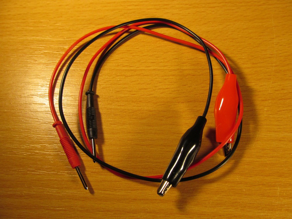
While the printer did its job, I took soldering iron, 2 and 4mm banana plugs with some accessories and prepared the "real" measurement probes. At first the 2mm--alligator clip type, simple and convinient
![]()
and then 2mm--4mm type, allowing standard laboratory accessories to be used
![]()
The alligator clips with 4mm banana terminal is harvested from some really old gear, much older than I am. All those probes are DIY and probably something like CAT 0.
So now, I've got a real multimeter, yay!
![]()
![]()
Now I have to make some tuning to firmware (displaying battery state), do a final calibration and produce some crunchy video of the gadget in action.
-
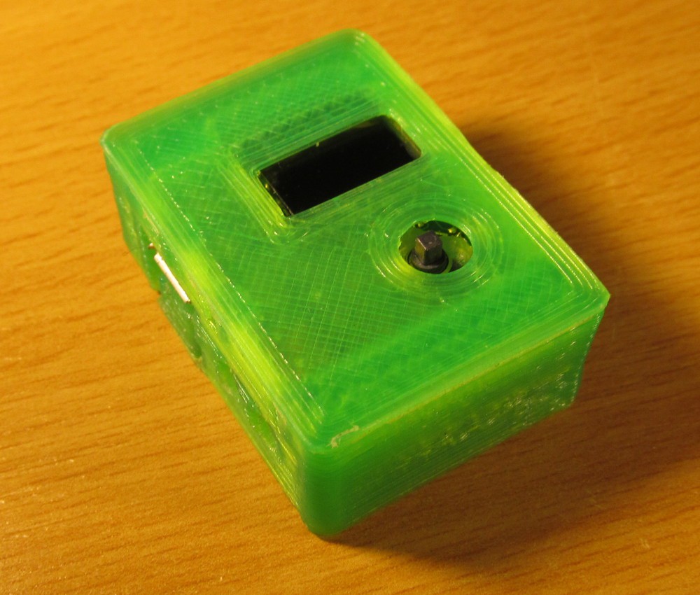
Getting closer
12/18/2015 at 22:26 • 1 commentIn last days I made some some more progress about firmware, mostly catching tiny bugs and doing clean-up while trying to free up some FLASH memory in order to pack more features into the firmware. I'm really running out of program memory, but it looks like the basic goals I set up at the beginning of the project are finished for now.
![]()
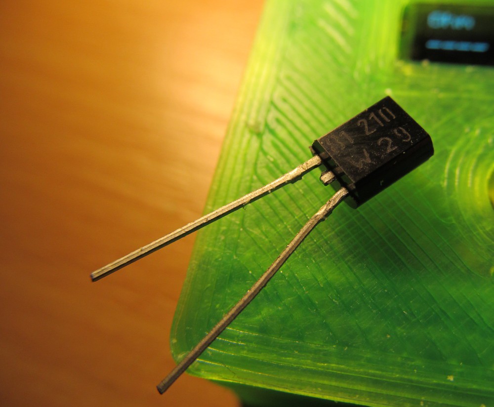
There is KTY81-210 sensor with leads directly inserted into 2mm banana plugs.
![]()
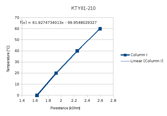
In normal measurement mode I can measure its resistance, as expected. The temperature-resistance dependence is in small range fairly linear
![]()
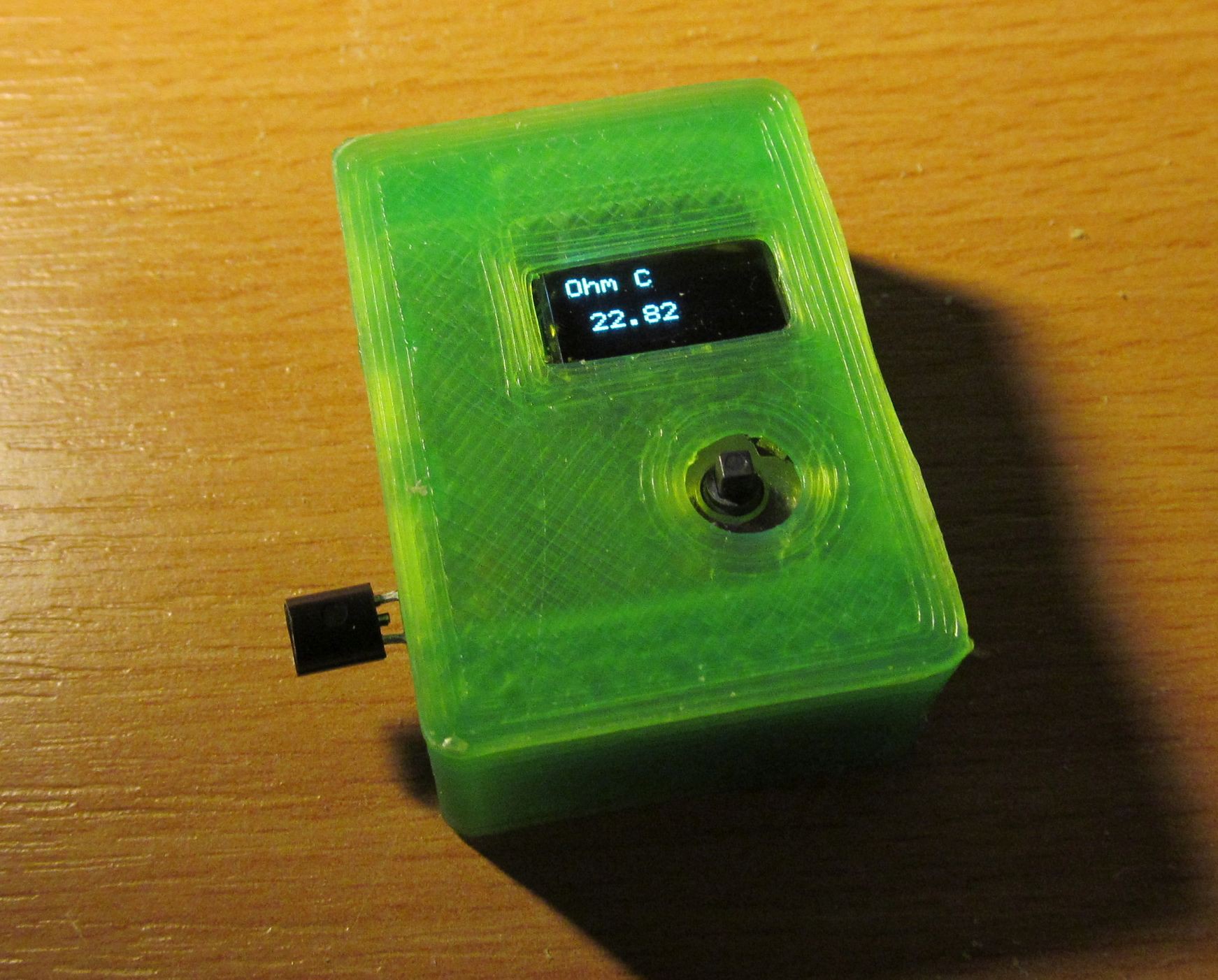
and after entering 0, 61,927 and -99,955 as polynomial calculation parameters into my micro progmeter and switching into calculation mode (note the C indicator) I got temperature result
![]()
what looks like temperature in my room.
By the way, this enclosure is already second revision. Call me stupid, but the joystick hole is still a bit off, because of my mistake. What more, I feel like the translucent green filament colour is underlining printout defects by poor hotend of my 3D printer, and I ran out of any other colour.
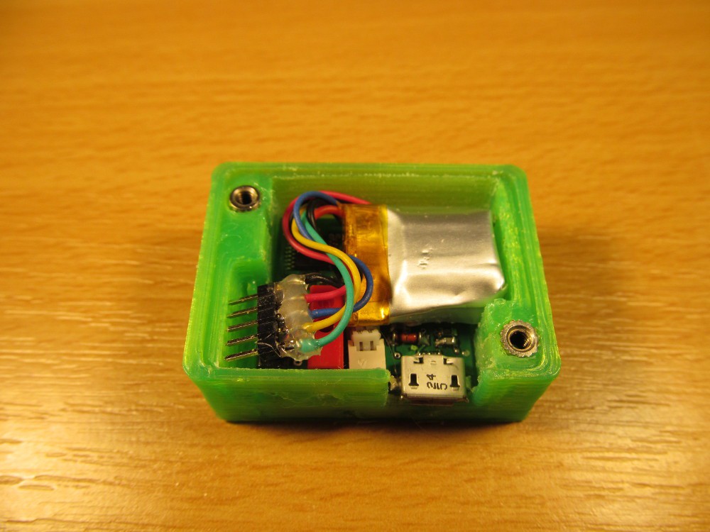
I soldered five wires and 2mm pinhheader (standard 2,54mm is way too big) serving as interim programming connector, but I think leaving it there wouldn't harm anyway.
![]()
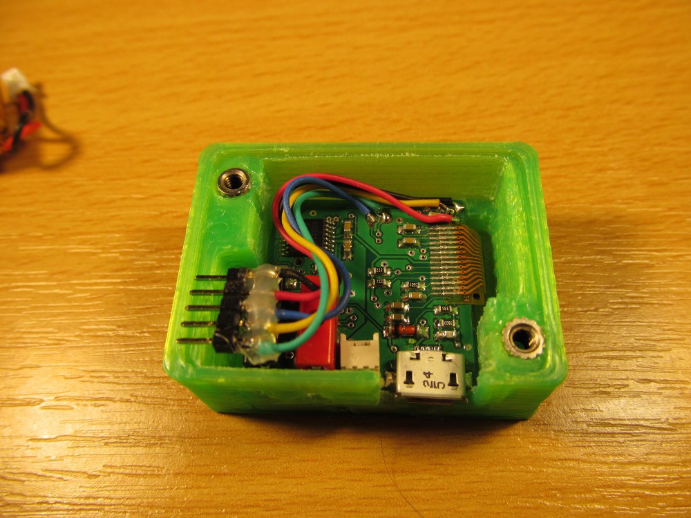
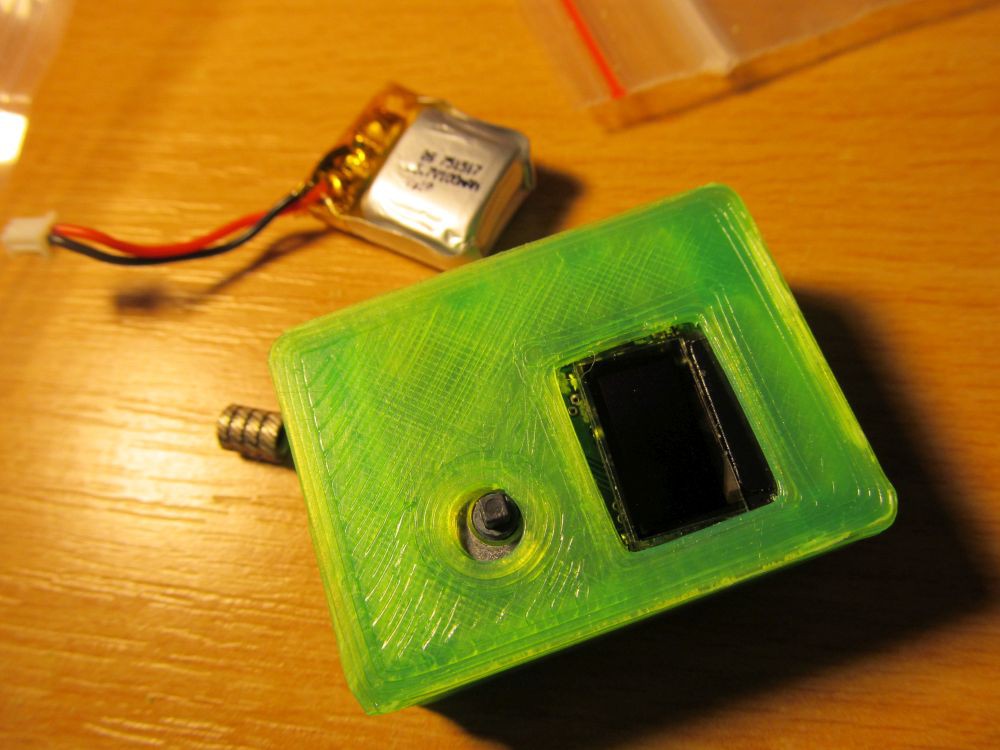
Pretty packed, with battery inside
![]()
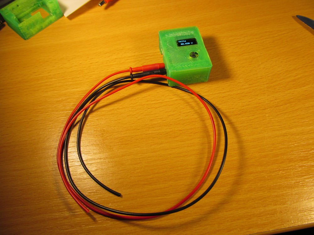
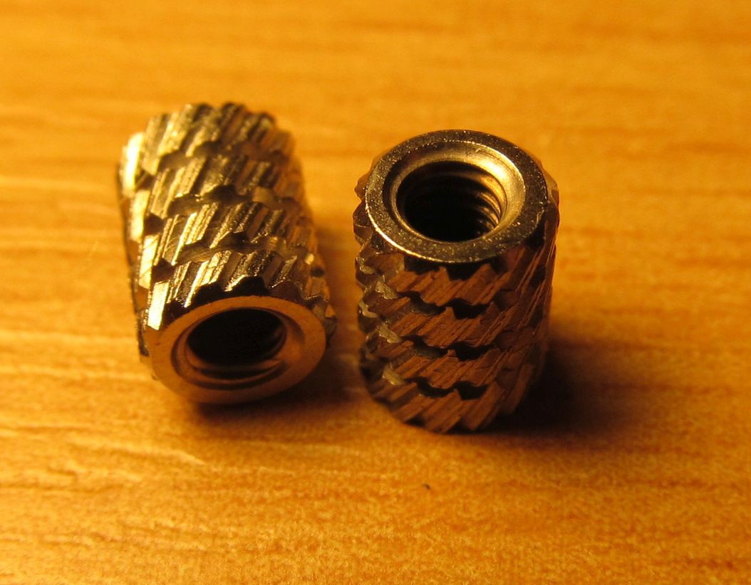
Threaded inserts are in place, waiting for 3D printed cover with M2,5 machine screws (or bolts? not sure about the terminology) and with test probes (with no actual probes attached) it reminds a DMM, somehow
![]()
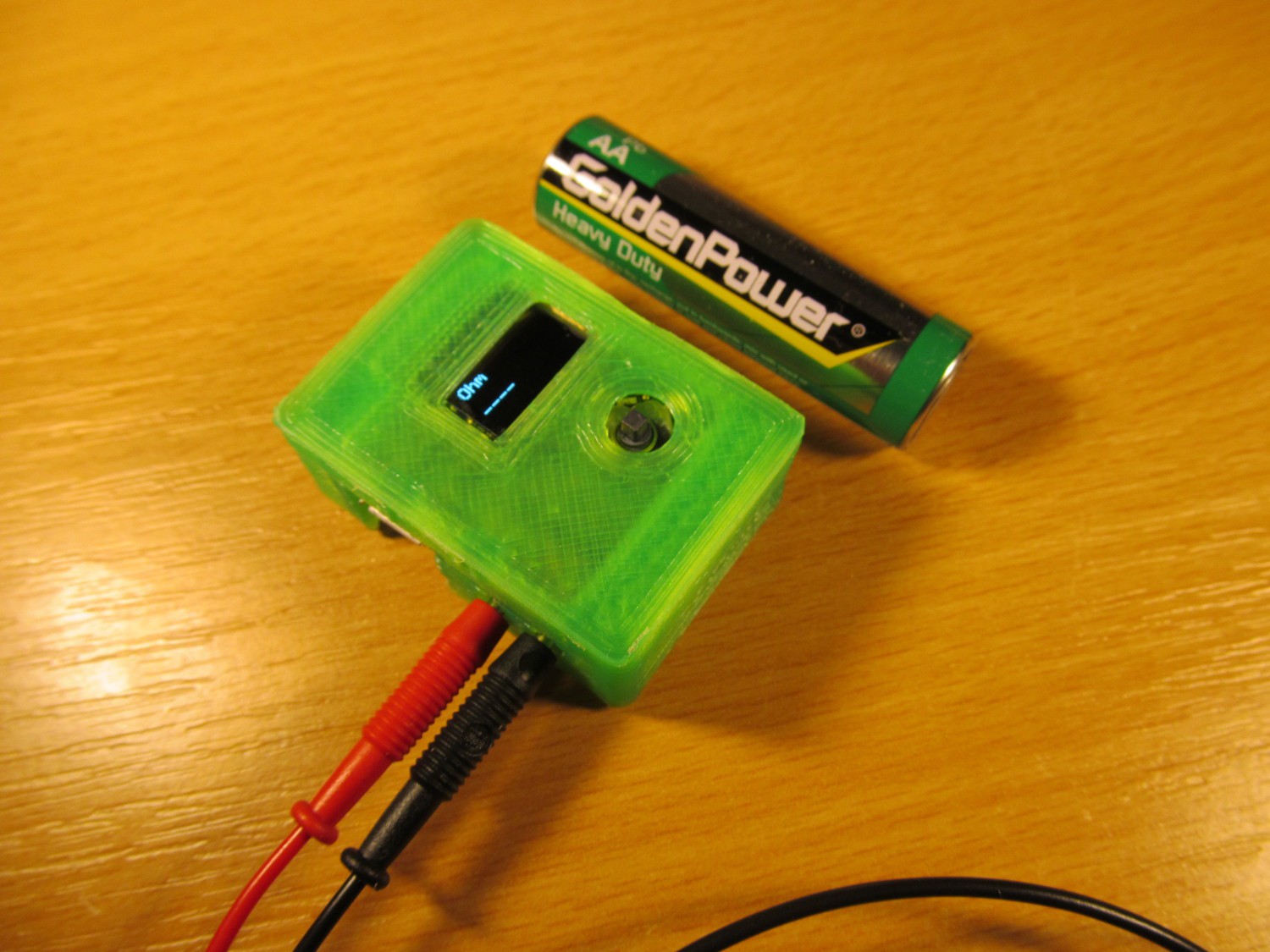
... and with AA battery for scale
![]()
So far so good. I need to make final touch to firmware, print the bottom cover for enclosure and finish the test probes.
-
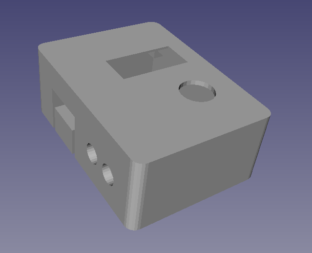
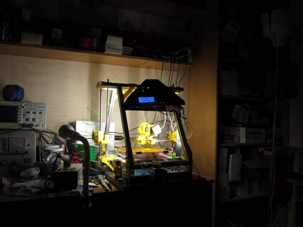
Enclosure design
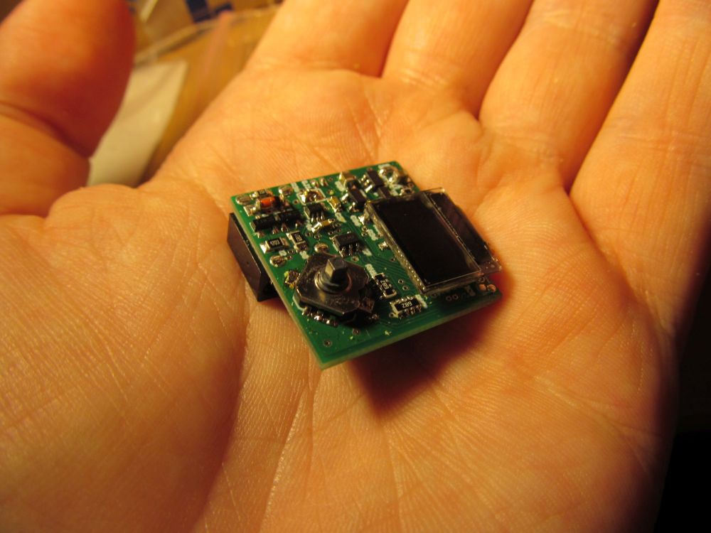
12/16/2015 at 10:26 • 0 commentsWhile firmware is taking the final shape, hardware is still nothing but barebone PCB.
![]()
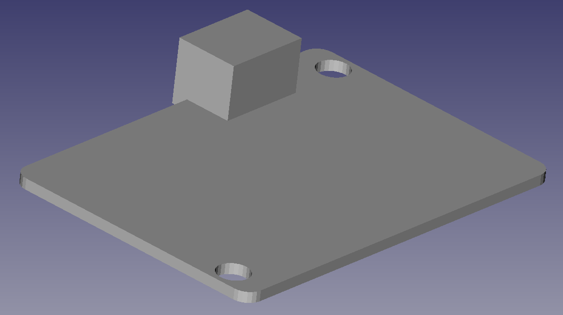
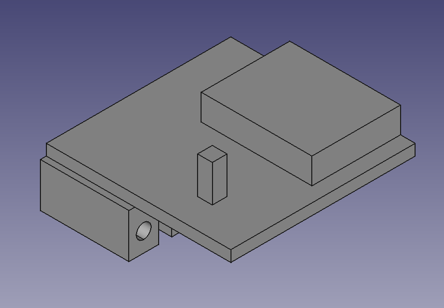
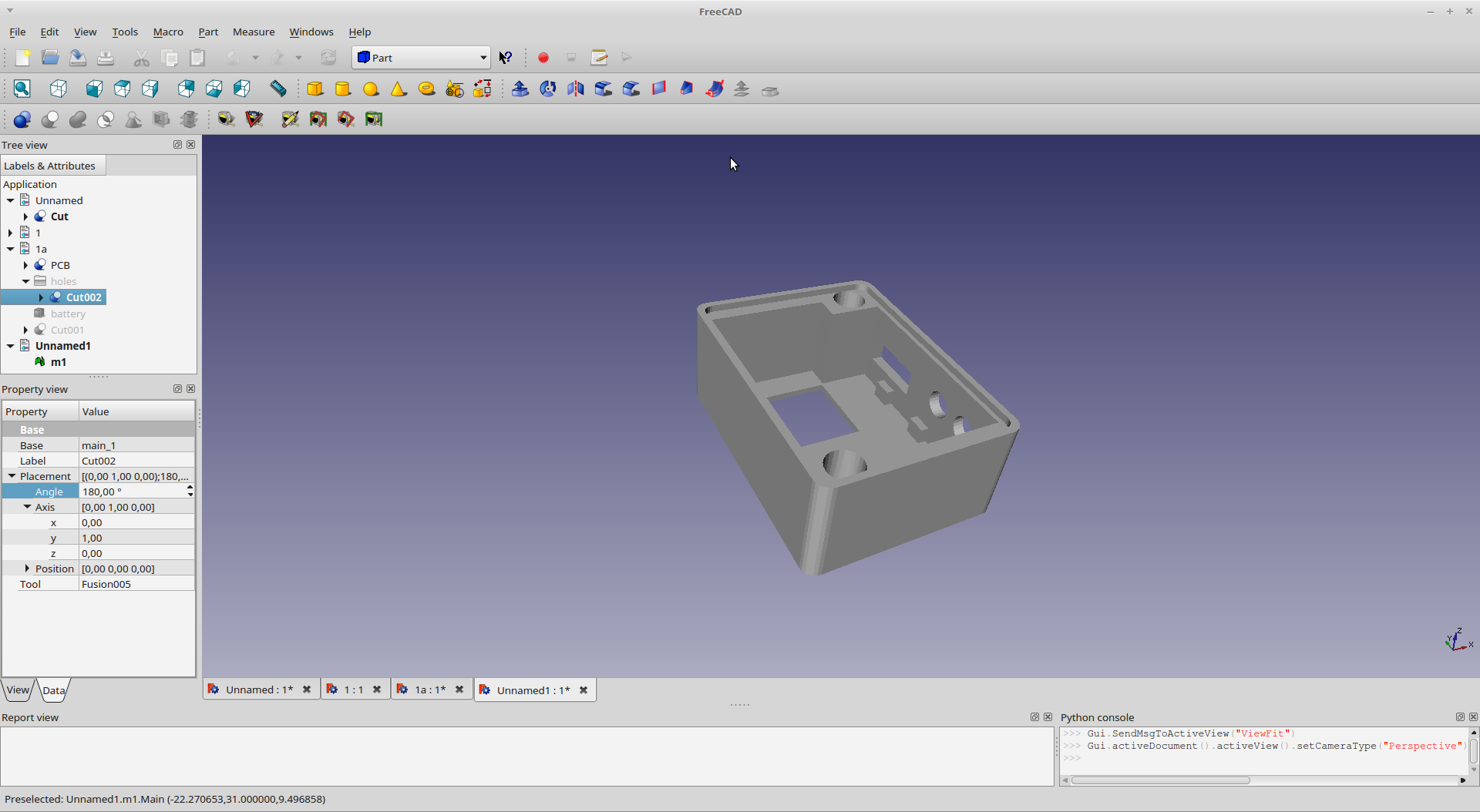
I started my favorite mechanical CAD Freecad and designed rough PCB model
![]()
and used it to design enclosure
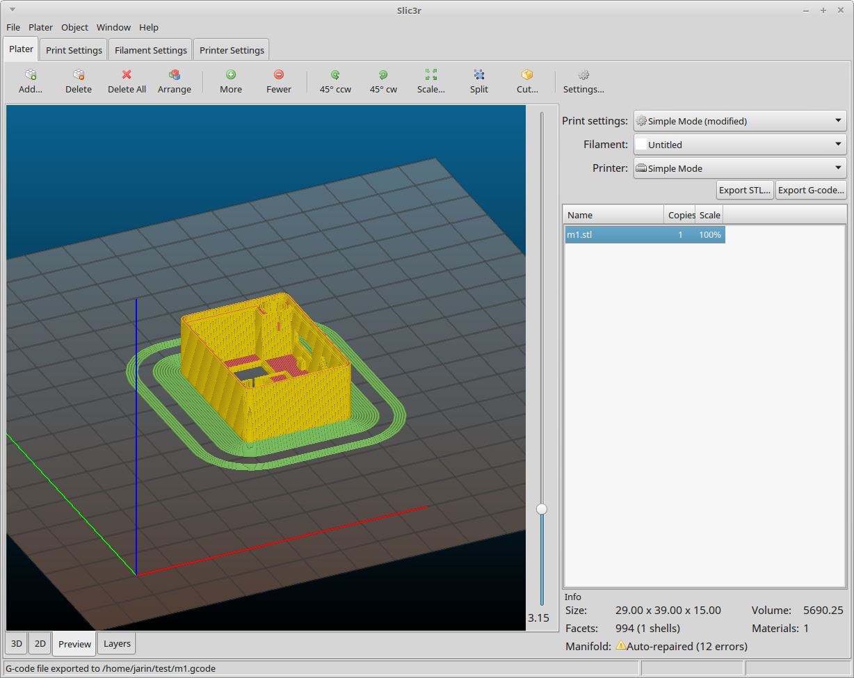
![]()
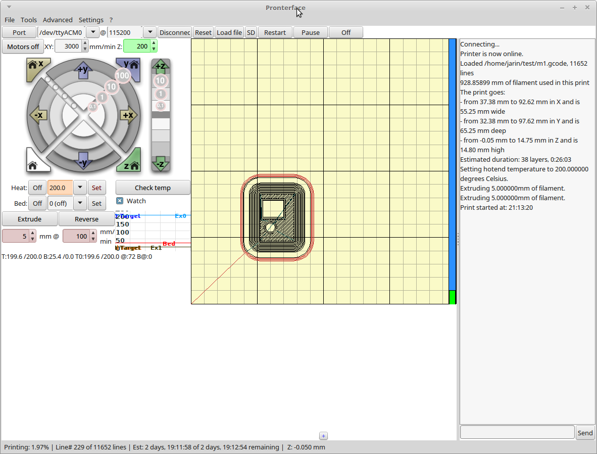
exported into slic3r
![]()
printed via pronterface
![]()
and my old crappy printer
![]()
and here is "not that great" result
![]()
Trying to fit the PCB inside:
![]()
Almost there. Hole for joystick a bit off, LCD windows is way too big, printing brim is not completely removed, but I'm on a good track. Oh yes, this time I'm designing the enclosure for threaded inserts for metric bolts instead of using self-drilling screws
![]()
I'm working on a enclosure design update. New firmware, as well as mechanical design files are being uploaded to github repository.
-
Firmware progress
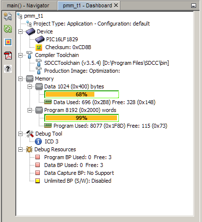
12/16/2015 at 10:21 • 0 commentsYesterday I finished first version of firmware - it is able to measure voltage up to 20V, measure resistances from zero up to 5MOhm with 10Ohm resolution and calculate something else from those measurements using second order polynomial function. Coefficients of this function can be entered by user via joystick - I must tell you it is as inconvenient as I expected. On the other hand, floating point routines ate a lot of FLASH memory
![]()
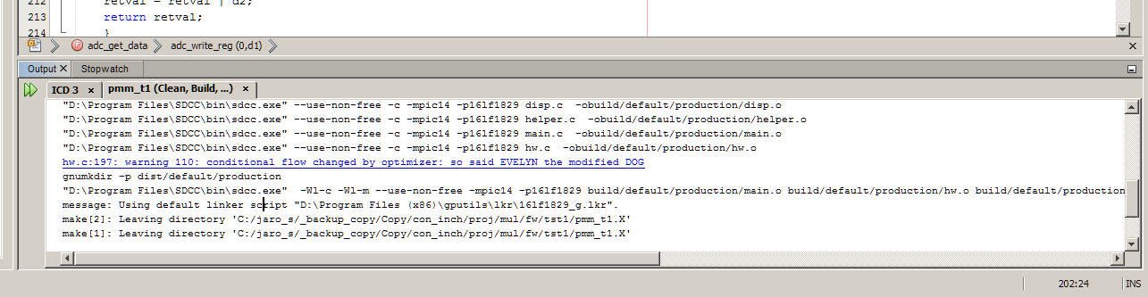
115 words of FLASH remaining. There is a few details missing (indication of battery state), so I'm going to find good use for this bunch of memory cells. Oh yes and it seems like SDCC authors do like Frank Zappa
![]()
Sorry for such as short project log, but hackaday.io page doesn't allow me to post more without getting error 413 message. Meh.