 Ian Hanschen
-
11Step 11
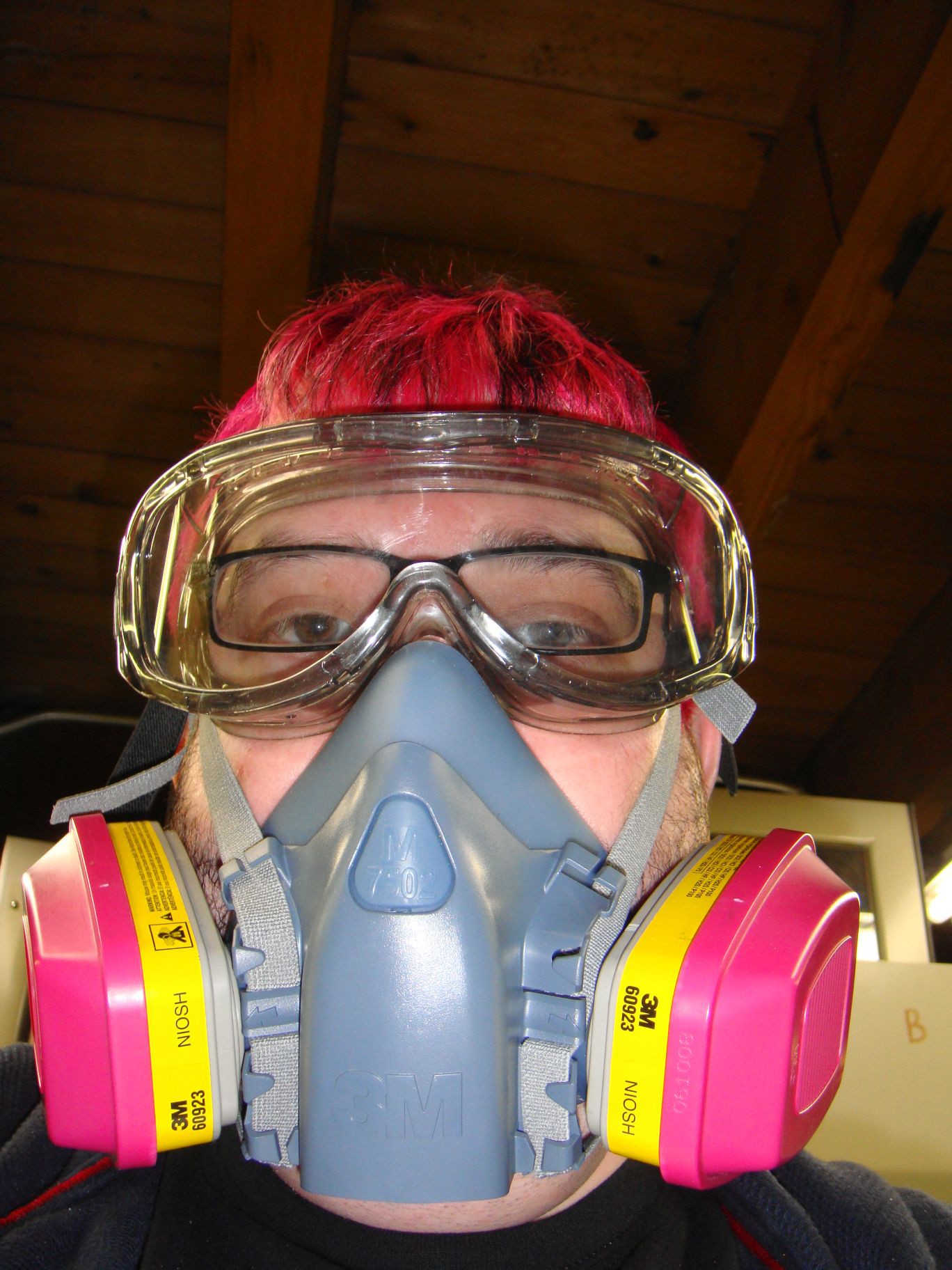
![]() Safety, engage.
Safety, engage. -
12Step 12
![]() Setting up the auto-pipetter to dispense 1200ul.
Setting up the auto-pipetter to dispense 1200ul. -
13Step 13
![]() Toluene being deposited in a vial with PFO-RED.
Toluene being deposited in a vial with PFO-RED. -
14Step 14
![]() The solution is heated at 80C for about an hour. Inside the vial is a small magnetic rod, controlled by a circular array of electromagnets underneath the hot plate. This spins the vial, stirring the solution at high speed, under heat.
The solution is heated at 80C for about an hour. Inside the vial is a small magnetic rod, controlled by a circular array of electromagnets underneath the hot plate. This spins the vial, stirring the solution at high speed, under heat. -
15Step 15
![]() This is MEH-PPV, a green light emitting polymer. I'll use this to make a green OLED.
This is MEH-PPV, a green light emitting polymer. I'll use this to make a green OLED. -
16Step 16
![]() First I spin coat PEDOT:PSS - this is a solution of Poly(3,4-ethylenedioxythiophene) poly(styrenesulfonate) gel particles suspended in DI water. It's complicated stuff, but PEDOT:PSS makes for brighter, more efficient OLED devices.
First I spin coat PEDOT:PSS - this is a solution of Poly(3,4-ethylenedioxythiophene) poly(styrenesulfonate) gel particles suspended in DI water. It's complicated stuff, but PEDOT:PSS makes for brighter, more efficient OLED devices. -
17Step 17
![]() A generous amount of PEDOT:PSS is applied to the anode side to be spin coated. I think I bought my spin coater from senz-it. It was cheap on ebay...
A generous amount of PEDOT:PSS is applied to the anode side to be spin coated. I think I bought my spin coater from senz-it. It was cheap on ebay... -
18Step 18
![]() Spin time and speed are set.
Spin time and speed are set. -
19Step 19
![]() The anode side now consists of the ITO-conductive electrode that was pre-deposited on the glass, as well as a layer of PEDOT:PSS for the hole transport layer (HTL).
The anode side now consists of the ITO-conductive electrode that was pre-deposited on the glass, as well as a layer of PEDOT:PSS for the hole transport layer (HTL). -
20Step 20
![]() This is the cathode slide, that hasn't been spun coat at all. It only consisted of an indium-tin oxide coating to make it conductive. Here, the cathode for the device is added. This is usually a low work function metal. Most low work function metals that are not alloys have a high melting point and are difficult to coat without a sputter coater or electron gun. So I'm using a liquid alloy consisting of indium, gallium, and tin. This is the metal droplet on the glass slide.
This is the cathode slide, that hasn't been spun coat at all. It only consisted of an indium-tin oxide coating to make it conductive. Here, the cathode for the device is added. This is usually a low work function metal. Most low work function metals that are not alloys have a high melting point and are difficult to coat without a sputter coater or electron gun. So I'm using a liquid alloy consisting of indium, gallium, and tin. This is the metal droplet on the glass slide.
 Safety, engage.
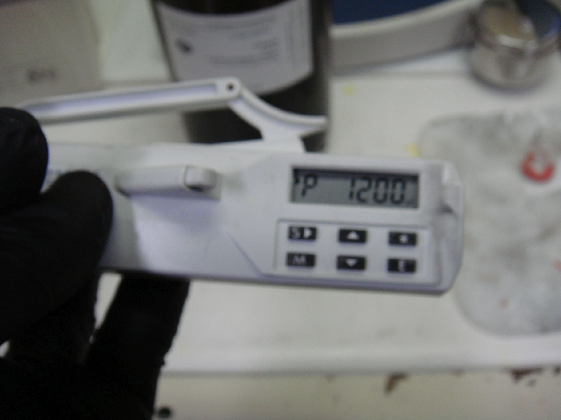 Setting up the auto-pipetter to dispense 1200ul.
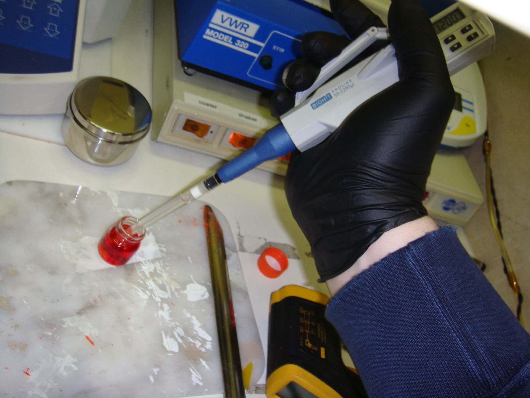 Toluene being deposited in a vial with PFO-RED.
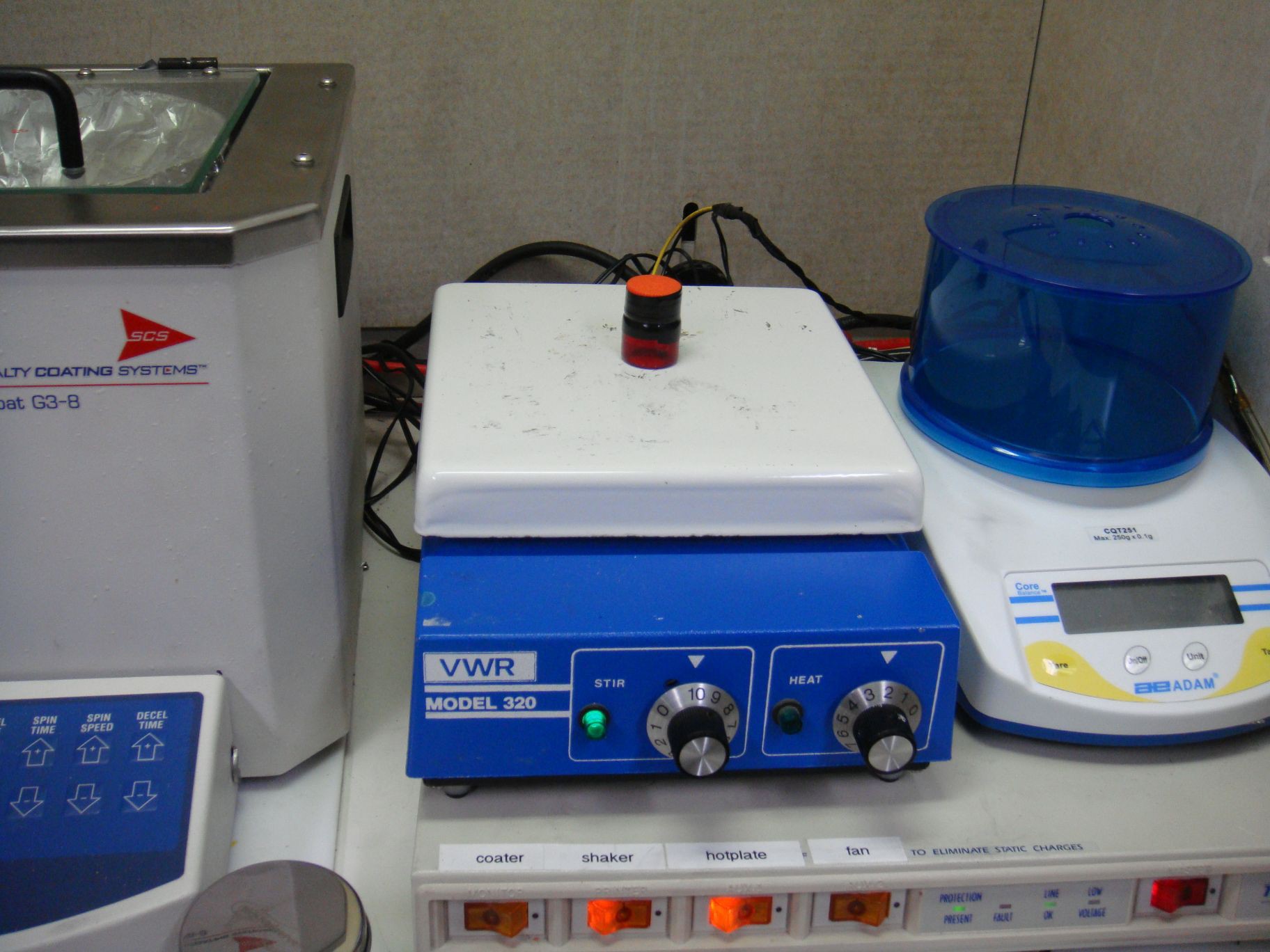 The solution is heated at 80C for about an hour. Inside the vial is a small magnetic rod, controlled by a circular array of electromagnets underneath the hot plate. This spins the vial, stirring the solution at high speed, under heat.
 This is MEH-PPV, a green light emitting polymer. I'll use this to make a green OLED.
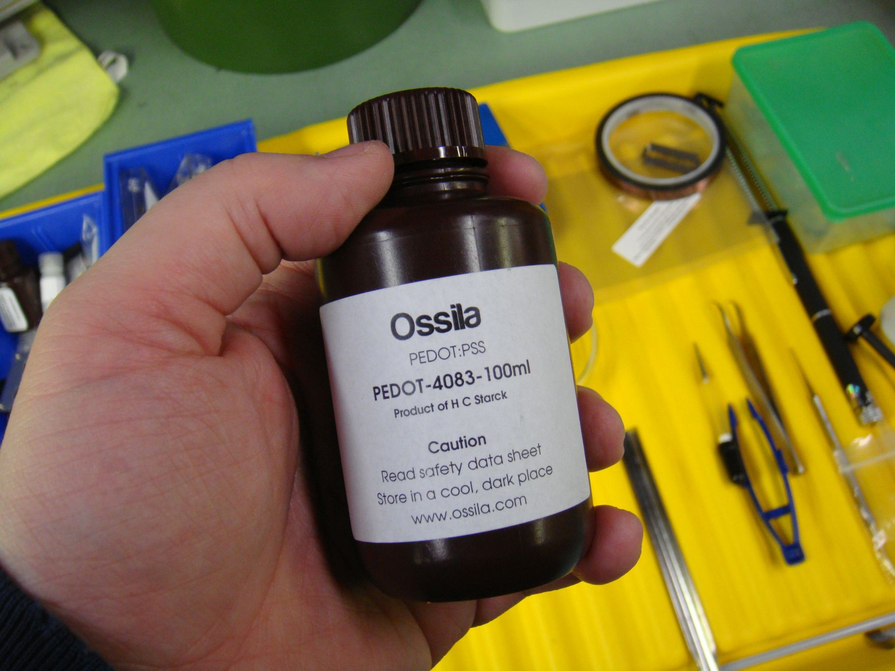 First I spin coat PEDOT:PSS - this is a solution of Poly(3,4-ethylenedioxythiophene) poly(styrenesulfonate) gel particles suspended in DI water. It's complicated stuff, but PEDOT:PSS makes for brighter, more efficient OLED devices.
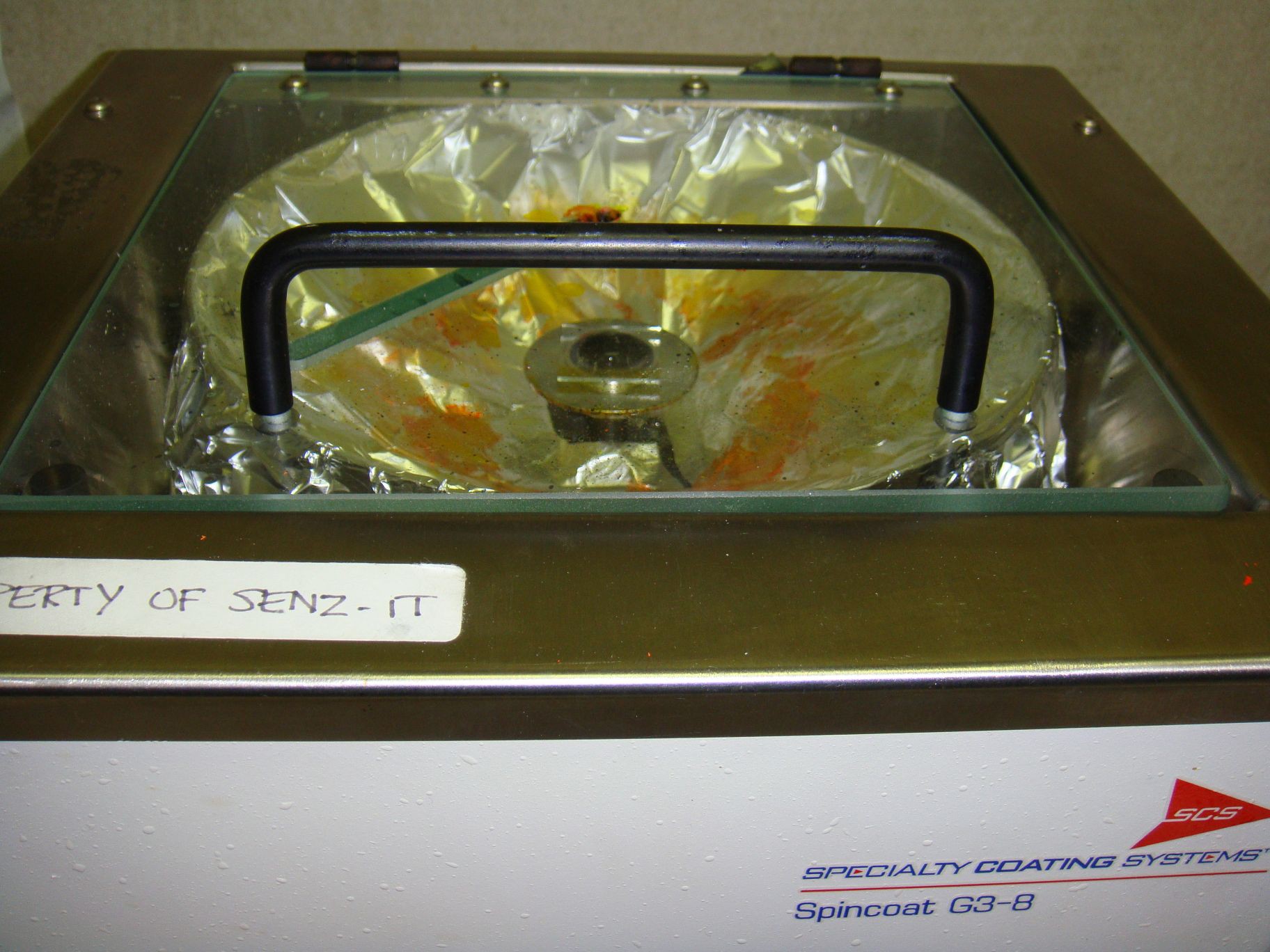 A generous amount of PEDOT:PSS is applied to the anode side to be spin coated. I think I bought my spin coater from senz-it. It was cheap on ebay...
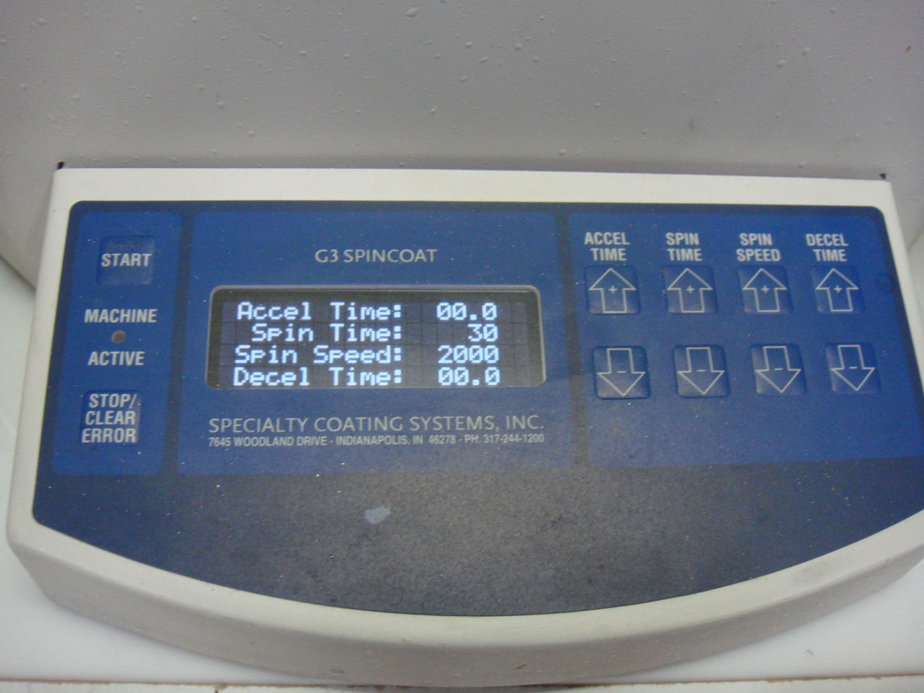 Spin time and speed are set.
 The anode side now consists of the ITO-conductive electrode that was pre-deposited on the glass, as well as a layer of PEDOT:PSS for the hole transport layer (HTL).
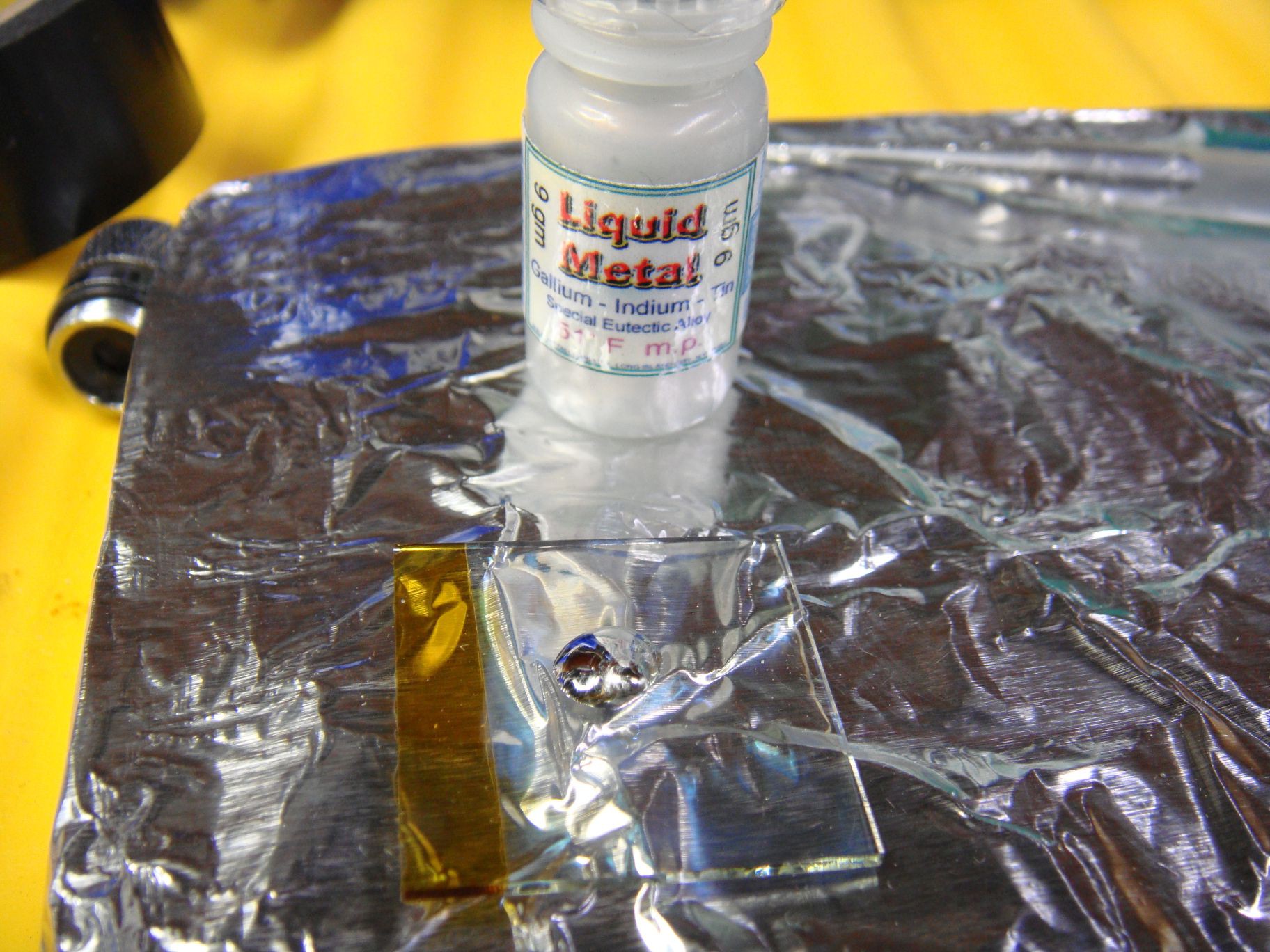 This is the cathode slide, that hasn't been spun coat at all. It only consisted of an indium-tin oxide coating to make it conductive. Here, the cathode for the device is added. This is usually a low work function metal. Most low work function metals that are not alloys have a high melting point and are difficult to coat without a sputter coater or electron gun. So I'm using a liquid alloy consisting of indium, gallium, and tin. This is the metal droplet on the glass slide.
Discussions
Become a Hackaday.io Member
Create an account to leave a comment. Already have an account? Log In.
I came across this wondering how OLEDs are made for brake lights. This is a pretty awesome write up. Thanks man.
Are you sure? yes | no
Hello and thanks . Did you measure the light intensity, driving voltage and the lifetime?
Are you sure? yes | no