It's all really quite simple.
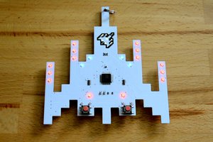
The ATTiny has 11 GPIO pins (it's a 14 pin package with power, ground and a RESET pin that can't be used for GPIO if you want to easily reprogram it). 3 of the GPIO pins are shared with the programming interface. The LEDs will be placed on the other 8 pins to insure that the act of programming doesn't apply any voltage to the LEDs. The button will be connected to one of the programming pins, because as long as it's not pressed, it won't interfere.
The reason we want to insure that programming doesn't connect up to the LEDs is that the LEDs represent a low impedance load, which may be too much for the programmer. More critically, there are no series resistors on the LEDs. This would ordinarily be a bad idea, but in this case, the firmware ordinarily insures that the LEDs are not turned on long enough to be damaged, and the amount of current the battery can put out isn't enough to damage the LEDs.
In laying out the board, you need to figure out how to arrange the battery clip, the programming interface, the button, the 8 LEDs and the ATTiny. I chose to put the battery clip and programming interface on the back, and the rest on the front. The programming interface is designed to work with a Pogo pin programming adapter. You should use a 3.3 volt AVR programmer, but if you must use a 5V one, then you should remove the battery first and not leave the programmer connected to the board too long, lest the LEDs be damaged.
The original version of the board had a space for a series resistor for each LED, but it became clear that 0Ω was the correct value, so the latest board omits it. The original board also had a smaller SMD pushbutton, but it wasn't very user-friendly. The new board has a footprint for a button that has a much better tactile feel.
One of the big limitations of this project is the amount of current that can be supplied by a CR1220 battery. You simply can't turn more than one LED on at a time without reducing the voltage from the battery so much that the processor browns out. This means that the code has to play persistence-of-vision games with the LEDs when it wants to make it appear that more than one of them are on.
To facilitate this, a timer is used to keep a millisecond counter. This counter is the "heartbeat" of the code. The LED patterns can change with a maximum frequency of once per ms. Making the timer interrupt at 1 kHz is tricky. The system is clocked from the internal 8 MHz oscillator, but to save power, it is pre-scaled down to 500 kHz. The timer is set up with a divide by 64 pre-scaler, meaning that to get it to interrupt at 1 kHz, it needs to count to 7 13/16. In other words, it counts to 8 13 times, then to 7 3 times. The result is 1 kHz. The timer compare interrupt not only increments the millisecond counter, but it also adjusts the compare value based on the interrupt count.
The only other tricky aspect of the firmware is that you have to bend over backwards a bit to insure that all of the data is kept in PROGMEM, and access it properly. The result is that with 5 different patterns from which to choose, the whole thing takes 2270 bytes of flash and 21 bytes of BSS (static variables that start zeroed out). I use ATTiny84s, though with this firmware, ATTiny44s could be used instead.
When you hold the button down, the tiny is put into its power-down sleep state. The pin-change interrupt on the button pin is used to wake it up. In this state, the controller uses around 100 nA of current. That's so little that the shelf life of the battery will kill it first. While it's operating, the controller draws around 200 µA of current, not counting any LEDs that may be lit. The LEDs will draw as much current from the battery as it will supply until the voltage sags. The ATTiny, fortunately, has a reasonably low drop-out voltage which allows it to keep running through it all.
 Nick Sayer


 bobricius
 lion mclionhead
 Chris Miller
 Mike Szczys
Hi! Very nice project. I was wondering if it would be possible to program the attiny using arduino. Do you have the .ino code?
It would be possible to use the attiny24 instead of the arduino 84?
Many thanks.