Bentendo64
-
Back from the Dead after 3 years?
03/23/2018 at 14:24 • 0 commentsI haven't worked on this much for the past 3 years. But yes, I am still alive, and I have been making progress recently. The big thing I've been working on is a board that has RS-232, an EPROM programmer, and a memory bank switcher. The memory bank register can be turned off because I have some plans to possibly implement some other complicated memory scheme with segmentation, or some other virtual memory-like function.
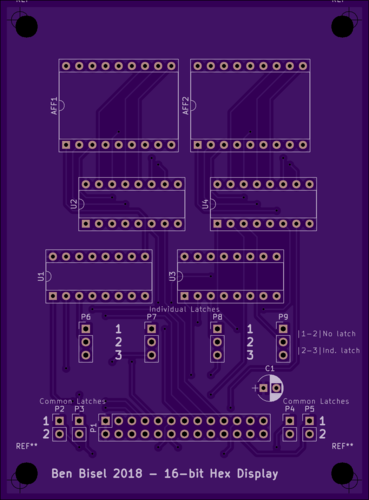
But we're back better than ever because now I'm making some PCBs instead of hand-wiring everything!![]()
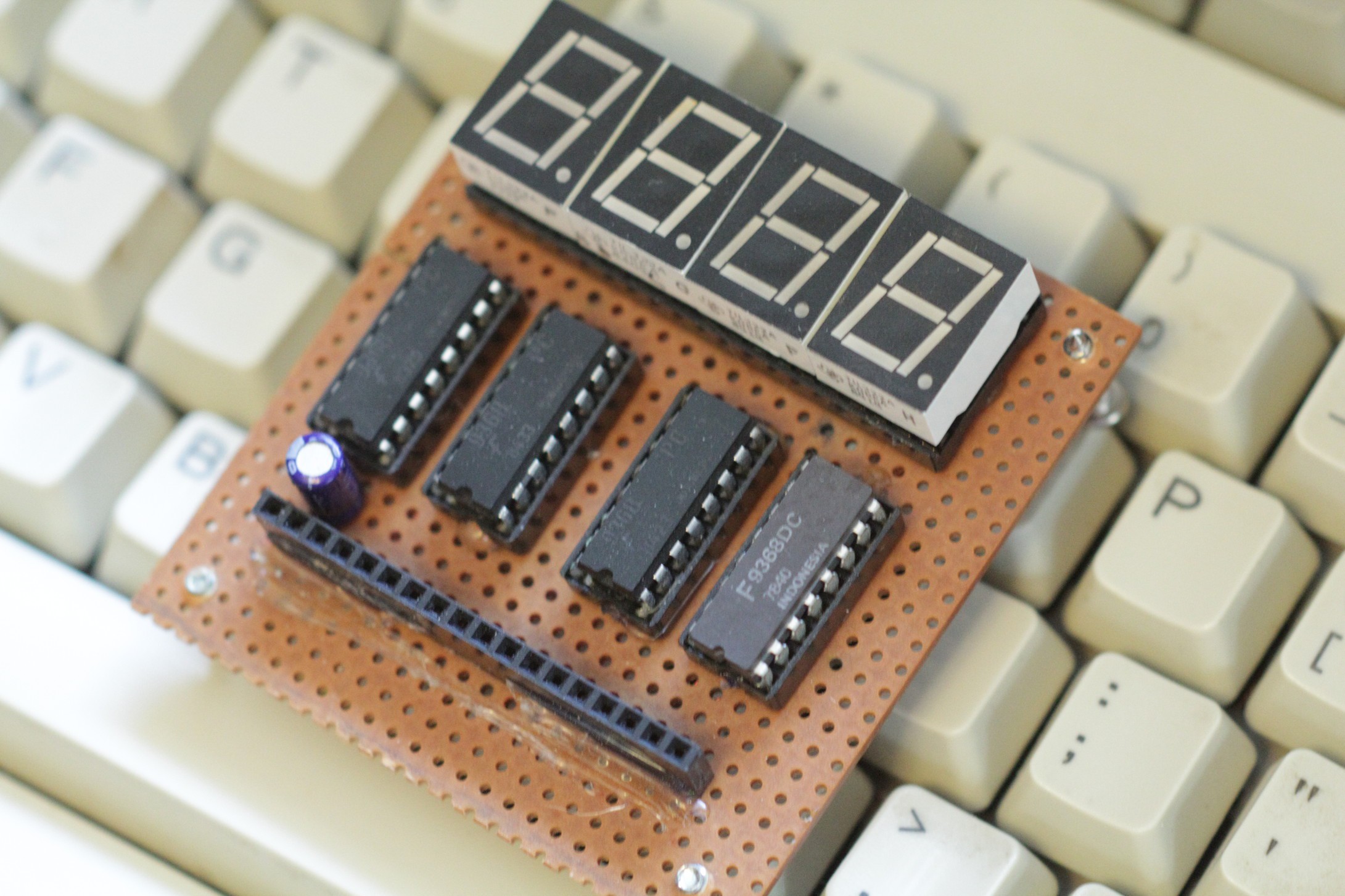
I do not have much experience routing PCBs, so I'll probably get the initial prototype done cheaply and see how it works. I made a different test circuit and sent it off to China for milling. It could be here anytime from now to May. It is a PCB version of the the hex-readout display you may have seen in previous pictures.![]()
![]()
So we will wait and see how it turns out!
Details to come later. -
8 kilobytes of RAM and hardware issues
03/11/2015 at 19:41 • 0 commentsI got the RAM board all wired up, and it works correctly. It doesn't work as it should, but it works as it's wired. Just look at the schematic:
![]()
And then think about the 8080/8085/Z80 and how they interact with I/O.
That's right. If I write or read to the I/O addresses from $FE-$FF, the RAM board will spit out the data located at memory locations $FFFF and $FEFE. Not good. I'll have to solve that with a 7420 and an NPN not gate connected to the IO/M control line.
That is only the minor issue, though. Something seems to be messed up with the address space in general. I wrote a program that writes a program to the RAM board (starting at $FE00) and then jumps to the program written in RAM. This program includes a hlt instruction. However, the processor is not halting. This is making me wonder if there is an address line stuck at 0 somewhere. I know the bottom 4 address lines are working correctly, as I have written functional programs that use that address space. I also know the stuck line would have to be stuck at 0, as the rom I'm using is located at address $0000-$07FF (or whatever it is for a 2k address space starting at 0). Whatever the issue is, I know it doesn't exist all the time, as I have let the cpu free run with the RAM card in and sometimes it eventually finds an infinite loop or halts. Other times it just goes through the RAM as if it's all 0's.
So I'm back. It turns out I was both right and just stupid. Somehow I had A14 and A13 swapped AND A9 and A10 swapped on the motherboard. That shouldn't have affected my program running, thouhg. How I was stupid is I was using trying to use the LDA instruction the same way you would use MVI A. The result was random data being written to data memory and thus no halt. Give me a break, though. I haven't looked at Intel assembly in nearly a year. I still have to fix the RAM board I/O thing, though.
A few issues I found that would mak it not work when testing came to light. None of them were from the board (the mainboard) acting differently than it was wired. Take a look at the schematic for that:
![]()
Number one is the two 74245's. My intention was to have the AD bus on the system card bus. However, if they are not both connected to the same thing on both ends, bad things happen. So I simply removed the one for the AD bus. The other issue is with the remaining 245. If you notice, the /WR signal is connected to pin 1, the direction pin. It was set up so when /WR was active, data would flow from the system card bus to the cpu. Not correct. So I just connected the /RD signal there now.
More pictures!
![]()
![]()
Mmmmm all those wires. About 340 solder joints on this card.
![]()
All 16 2148 SRAMs seated with address decode chips.
![]()
Running some code (the LED is hooked up to SOD).
![]()
My testing method.
![]()
How I program the NVRAM (not pictured: the NVRAM chip).
-
It's been a while
02/09/2015 at 01:56 • 0 commentsIt's been a while since I posted anything or updated this project. But alas, it is still alive. What I have done since making this page is
- "Finished" the motherboard
- Have gotten about half way done soldering the 8k SRAM board
"Finished" is in quotes because I'm still on the fence about bank switching some memory and that would require soldering more wires on the main bus. Also, I made a slight mess up where the jumper for pin 39, the HOLD pin, is soldered to 5V, not ground. That just means when I start it up, the cpu just stares at me with the data bus in tri-state.
But anyway, here's some pictures and a video of it running nops. I have a 4 MHz crystal in there right now so it's running at 2 MHz, not 3. I don't have any 6MHz crystals.
Here's the bottom of the board:
![]()
And here's the naked top:
![]()
Here's what I have for the SRAM board so far:
![]()
Only 10 more wires to go! (times 17 solder joints).
I guess I could have made that a GIF. Or re-recorded it (I recorded this over 6 months ago).
Anyhow, I'm planning on purchasing a Ramtrom FM-1808 at some point soon for a quick and easy way to get some code running. I should have the SRAM board done within the next week, hopefully.