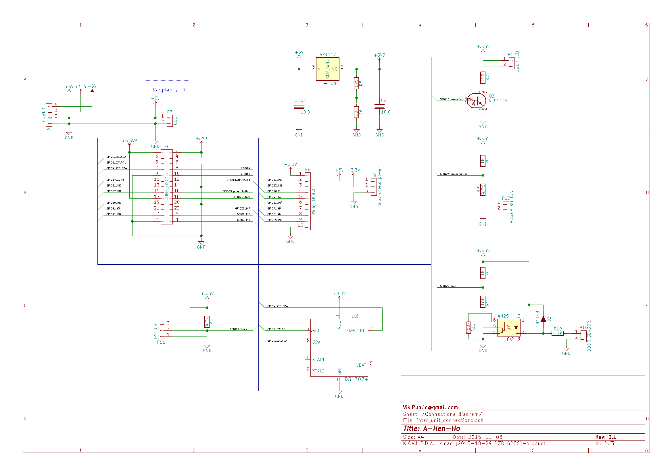
There is approximate schematics of the interface board. As far as RPi can't supply properly external hardware from it's on-board 3.3V LDO, I have to make my own supplied from a powerful 5V line. DS1820 will be connected using 3.5 jack connector, the pull-up resistance placed inside the case. Power-off button will be inside the case, no real protection needed. Power-on LED is connected using transistor to take as less as possible power from a RPi and at the same time to offer enough current. Door lock-open sensor will be connected using wires of the undefined length. This is why I will do a protection of the input. I think just transistor will not be enough. Both input buttons should connect ground to a input circuit. I think it is more safe, than connect a voltage line.

Only two GPIO left free...
Discussions
Become a Hackaday.io Member
Create an account to leave a comment. Already have an account? Log In.