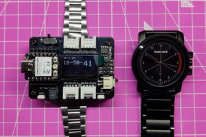
Using the ESP-Link Project (https://github.com/jeelabs/esp-link) as the software, I tried to see if I could squeeze an ESP8266-based AVR programmer into a square inch for the #The Square Inch Project! With a standard 6 pin ISP header, it's ready to interface to all your existing projects, and the onboard 3.3V / >3.7V selector switch means you can power the ESP8266 using your project's power.
Details
After a successful routing, the boards have been sent off to OSH Park and will hopefully be back in time for the deadline... fingers crossed!
Components
1×
ESP8266
-12 Module
1×
LM1117
Power Management ICs / Linear Voltage Regulators and LDOs
This sounds pretty cool but I don't quite understand how the ISP protocol is implemented since the ESP-Link project only mentions programming AVRs with a serial bootloader.
Btw: In the schematics it looks like GPIO14/SCK is connected to Reset/GPIO16 which isn't the case, is it?
Thanks for the reply, writing your own module clarifies things a lot. From the description it sounded like it should work right out of the box with ESP-Link. It'd be great if you could make your firmware work with ESP-01 modules as well, using RX & TX as GPIO.
I should have guessed it was one of those late night schematics ;)
Just a friendly reminder to please upload your design documents by 23:59 UTC on Dec 8, 2015 to be in the running for #The Square Inch Project!