Close
0%
0%

Everyman's turbomolecular pump

(Maybe) access to the high vacuum environment for the rest of us

Similar projects worth following
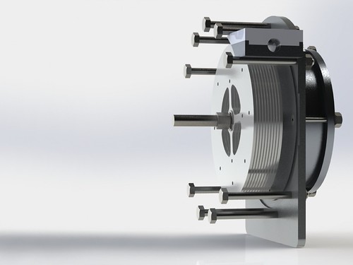
A short tube filled with a series of 40-60 high speed smooth discs. Based on Tesla's "Bladeless Turbine" design, operates using the boundary layer effect and centrifugal force.

The General Idea

I want a vacuum pump. Mainly so that I can aluminize my own mirrors. Yes I know you can send them off to a company and get it done for pretty cheap. But I want to do it myself, in my garage, and this being Hackaday I trust that you are ok with that too. Plus, it occurred to me that hackers (or at least hackerspaces) having access to the high vacuum environment could open up some interesting new possibilities. So, my little experiment might actually be useful to other, smarter people than me doing really cool stuff. Here's some things that require a decent high vacuum to do (from this site, a great intro to vacuum technology and challenges):

Electron tubes, vacuum tubes, electron microscopes, hard X-ray tubes, thin film evaporation, particle accelerators, radiometers, light bulbs, thermos bottles, certain lasers, other cool stuff...

Why This Is Hard

Briefly, air doesn't behave properly at really low vacuum, so normal "displacement" style pumps don't work, and you need other exotic pumps to continue moving air. It goes from normal to "Knudsen" flow, then "molecular" flow at moderately low vacuum. The two most common types of pumps for this flow regime are oil diffusion and turbomolecular, though there are others. Oil diffusion pumps are only semi-cheap, very messy, and have a habit of catching on fire if too much air is accidentally vented into them. Turbomolecular pumps are awesome on the other hand. They are very fast, clean, and expensive (several $thousands). They are similar in construction to mini jet-engines (i.e., not something I can build in my garage). Also, they cannot exhaust to (or function in) atmospheric pressure, and thus require a small backing pump ($100 or so I think).

The Stretch Goals (this is where you can all laugh at me)

An inexpensive vacuum pump for the hobbyist / hacker community

  • Easy to construct with minimal tools and readily available materials (As in Lowe's and Amazon for consistent prices)
  • Safe and robust - able to experience sudden loss of vacuum or power and not self destruct
  • Ultra simple fitting to vacuum chamber with minimal extra parts/seals/vents
  • Capable of :
    • Pulling a vacuum to 1.33x10^-5 Pa (10^-7 Torr)
    • 7.6x10^9 total compression ratio (with minimal stages)
    • Operating in and backing itself to atmospheric pressure

Those familiar with vacuum technology will realize that these goals are ludicrous. I agree wholeheartedly. I also believe that good design strives to stretch the imagination and push the bounds of what is possible, so I think having something ludicrous to shoot for is actually a good thing. If I build this thing and it works, everyone wins. If I totally fail and it never works, I will still have learned something about fluid dynamics, mechanical engineering, and materials science, so I still win. If I document my failure well and you guys can read about what I've learned, then everyone wins! Point is, don't be writing in the comments saying this is impossible. I already know it is (most likely) impossible. I want to find out how close I can get.

Math-less Design Overview

My design concept is based on the "Bladeless Turbine" invented in 1909 by Nicola Tesla. Patent is here. For those unfamiliar, briefly, Tesla's design utilizes the boundary layer effect to move air, rather than blades, and so enjoys fairly simple construction. It consists of several closely spaced smooth discs with a hole in the center for the intake, spinning at high speed. Viscous fluids (liquid or gas) stick to the discs and are propelled towards the edge by centrifugal force, and from there are exhausted. To my knowledge (after much searching on the Google), it appears that no one except Tesla himself has attempted to use this style of pump for high vacuum applications. Intuitively (and experimentally) the pumps are more efficient and effective with high viscosity fluids. For air, viscosity and pressure are inversely related, thus the pump should become more effective as the pressure decreases.

My stretch goals...

Read more »
Diffraction Grating Vacuum Measurement.xlsx

This a a simple excel file for calculating the measurement ability of various lasers/diffraction gratings. Fill in the highlighted blocks. Some common numbers for lasers and gratings can be found on the right side.

sheet - 10.44 kB - 03/22/2016 at 22:05

Download

  • First experiments with disc "vacuum" pump

    Keegan Reilly03/19/2018 at 20:49 3 comments

    The Setup
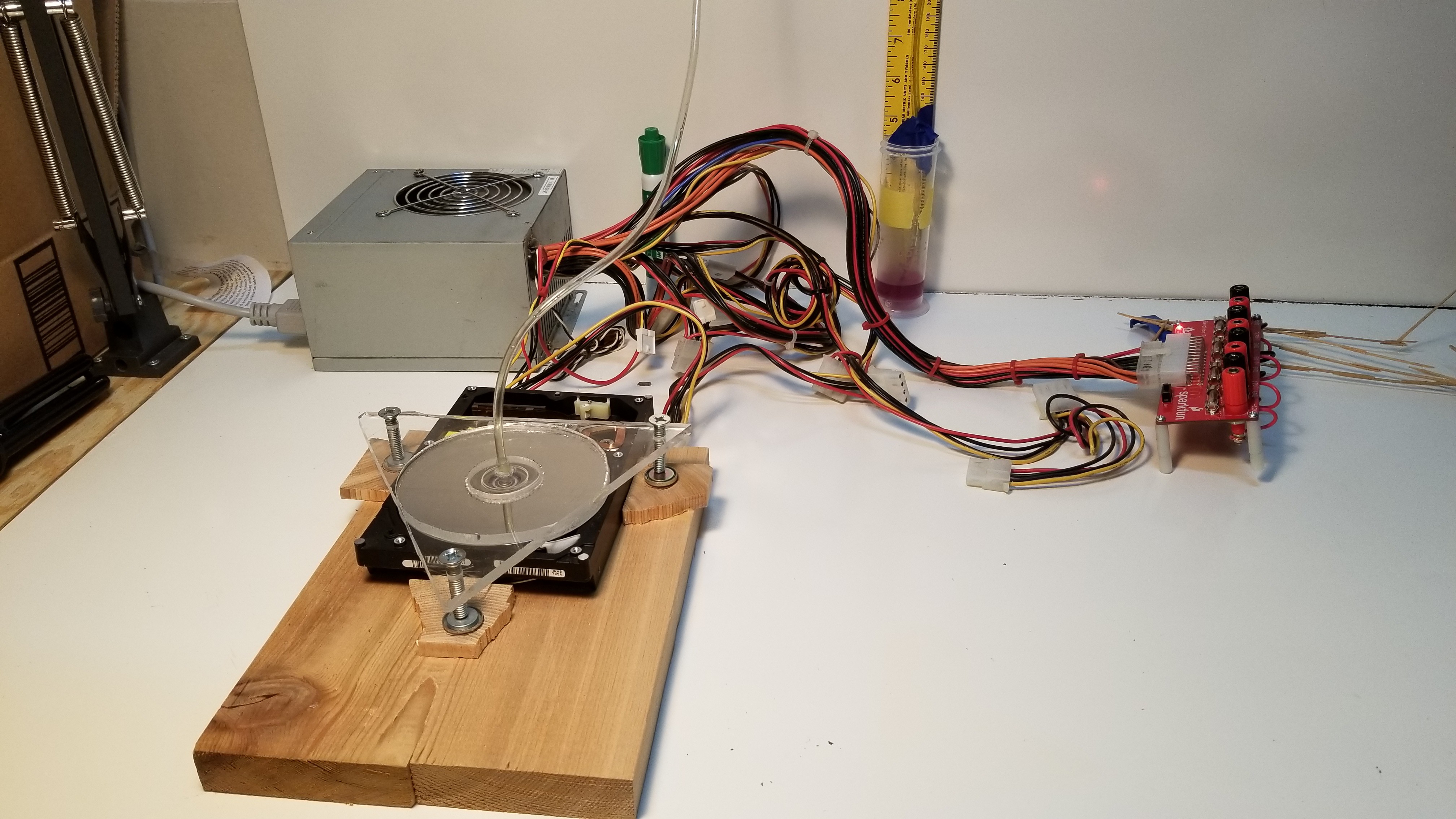
    Top left: old PC power supply, front: Hard Disc Drive Test Assembly, back wall: yellow ruler with water filled tube to measure vacuum pressure

    Welcome back folks!  It's been a long time since I've been able to make any headway on this, had to wait a while to scavange just the right parts.  I got a free PC power supply and some old hard drives, and decided to massively simplify the device in order to run some very initial experiments and verify my  hypothesis.  I did NOT expect this to approach anywhere near "high vacuum" or even what could be considered decent "roughing vacuum".  This is a highly simplified device to test the relationship between gap width and peak pressure differential produced.  

    In brief, the device was far less effective than even my meager expectations had allowed.  I may yet submit this to "Fail Of The Week."  However, it did work well enough to show that a smooth rotating disc can indeed pull a slight vacuum against atmospheric pressure.  To my knowledge, this has never been tested before in the literature I could find.  

    The Setup: Rotor, Stator, and Motor

    Main Test Platform

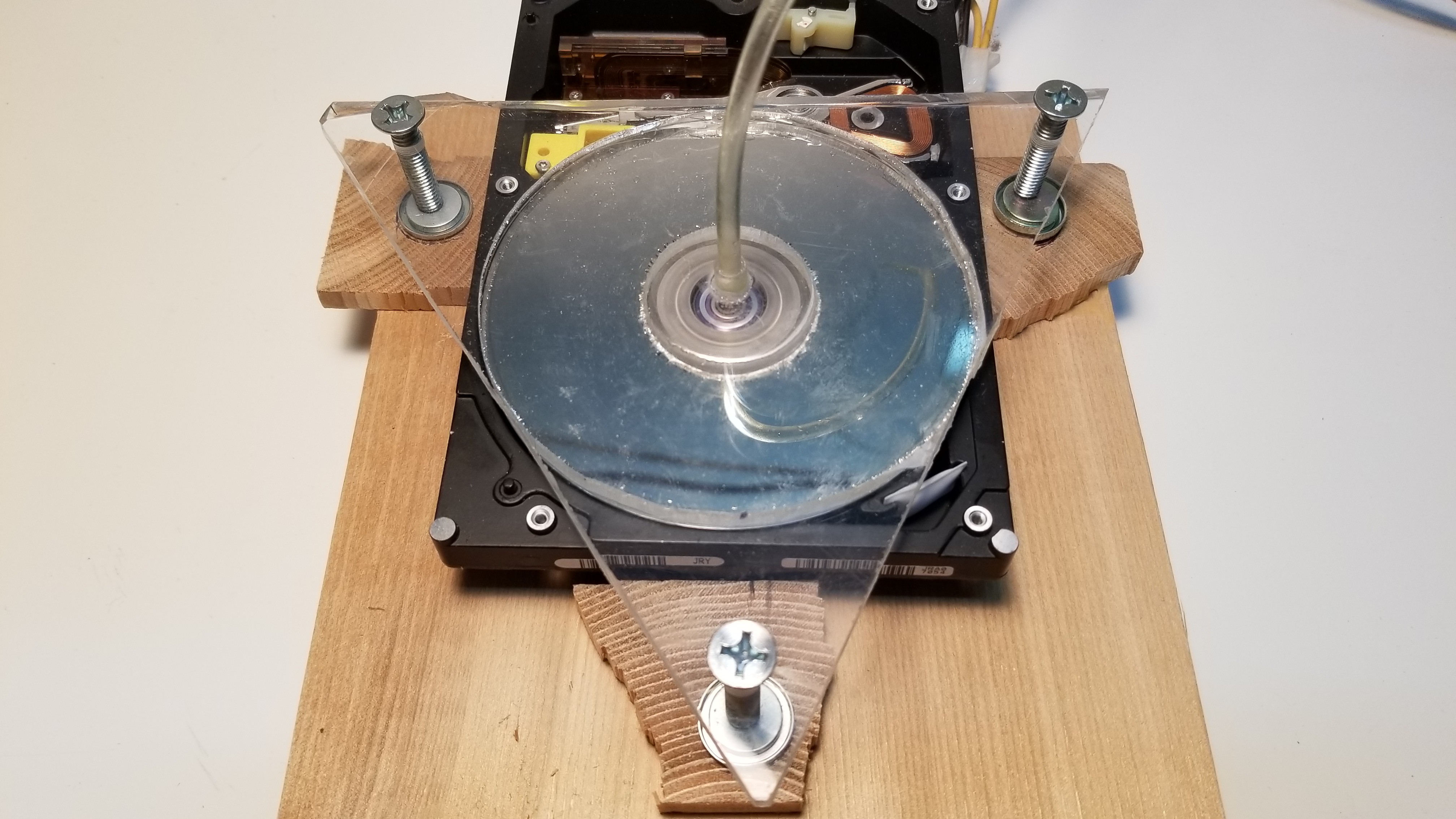
    Main test platform, consisting of HDD with cover removed and read head repositioned. The stator is the clear acrylic triangle mounted above, positioned by 3 fine bolts

    A HDD makes an ideal rotor, as it is perfectly balanced for high speed operation and perfectly flat to allow extremely small gap widths.  For this experiment I am simply using the stock circuitry to drive the motor at its intended 7239 RPM.   In future experiments I may attempt to make that speed adjustable.  The stator is made of clear acrylic (eventually I hope to observe Newtons rings to fine tune the gap width and stator position), and also forms the bottom of the "vacuum chamber".  It leads directly into the pressure measurement tube (center).   The stator angle above the rotor is tuned by carefully turning the 3 point bolts to make it as parallel as possible.  The bolts are fixed to the platform on 3 strong magnets.  

    The Setup: Pressure Measurement

    Simple Vacuum Measurement
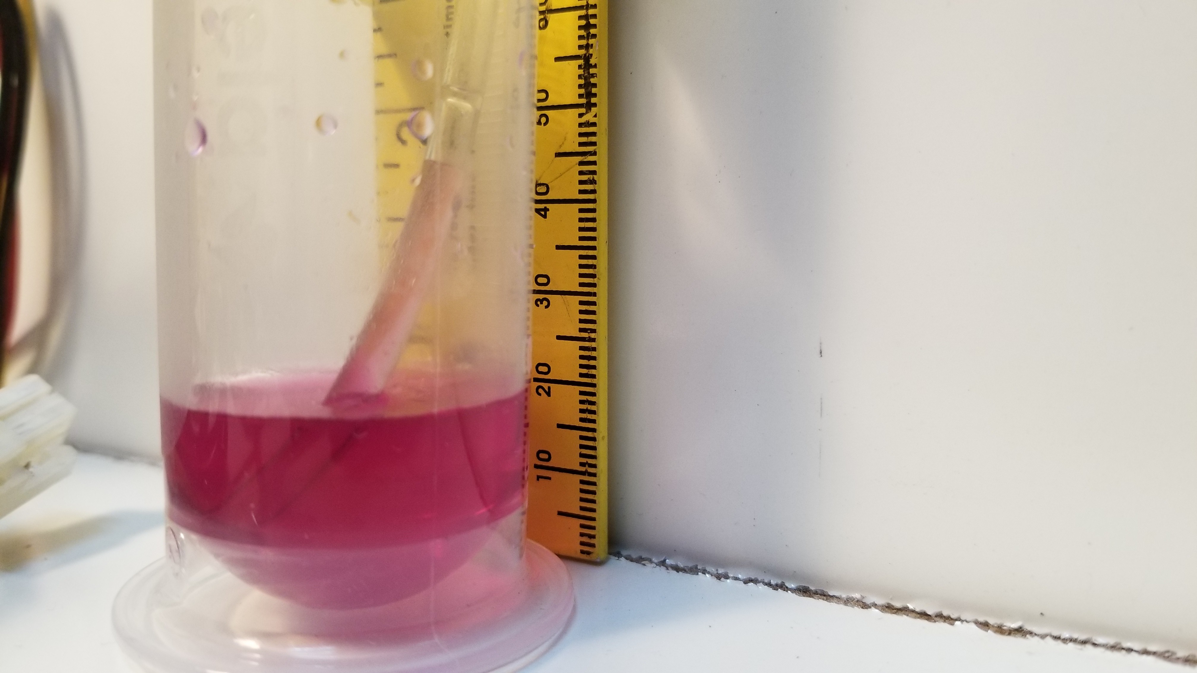
    Water and food coloring, pushed up the clear tube leading to the center of the stator. Height of the water column is read on the yellow ruler in the background. Measurements are in cm

    Pictured above is the best result I could get on my first day, 2.4cm of vacuous glory, barely 0.036 PSI below atmospheric pressure.  Using a water column has several distinct advantages.  It is super cheap, and requires no calibration, since the height of a water column is already a standard measurement of pressure differential.  

    Results and Discussion:

    There were a number of problems with this setup, mostly due to it being hastily "hacked" together.  This is Hackaday after all.  

    Problem 1:  The acrylic stator was not perfectly flat.  If I rested it directly on the HDD before turning it on, the acrylic could be rocked back and forth, so it was somehow bent lower in the center.  This limited the minimum gap width I could achieve to no less than about .5mm.  

    Problem 2:  The bolts are too wobbly.  The stator had a tendency to wobble laterally, causing the center to crash into the raised center mount on the HDD.  

    Problem 3:  My gap measurement technique was not accurate enough to get anything other than qualitative results like the above picture.  It is working, but both the gap measurement and stator positioning are too inaccurate to extrapolate any sort of generalized functional equation of performance to guide future engineering efforts.  

    I will have to address these 3 problems before I can get more useful data out of this setup, but I do think there is more to be learned from it given those tweaks.  

    On the plus side, I have verified that Tesla type disc rotors can indeed work as (rudimentary) vacuum...

    Read more »

  • In science, never say 'oops', only 'Ah, interesting!'

    Keegan Reilly06/21/2016 at 12:32 0 comments

    Still poking away, but I'll be out of town a lot soon for work, so we'll see how this goes. Used some silicone caulk to make a seal a couple weeks ago, and stuck an empty jam jar over it just to see what would happen. Also made a crude crookes radiometer to get a rough idea how close I was getting to the needed roughing vacuum.

    I never got my radiometer to spin, even in direct sunlight, though I couldn't tell for sure whether the issue was with the vacuum or the radiometer itself. That's the problem with trying to get two experiments working at the same time.

    Anyway, I left out alone for a while to think, and came back to it about a week later. To my dismay, the vacuum had managed to pull a bunch of oil out of the vacuum pump and collected out in the jar. This was going to be a royal pain to clean up now. Oops...

    Then I noticed the bubbles, streaming in from all around the edges. The issue is at least with my silicone seal! Ah, interesting. The good news is this means there's still a chance my cheap pump might work. Here's a link to video of you really want to see the bubbles.

    https://goo.gl/photos/xtBzxkbGbeoLadc76

    Back to the drawing board...

  • Got a roughing pump working!

    Keegan Reilly04/26/2016 at 03:18 0 comments

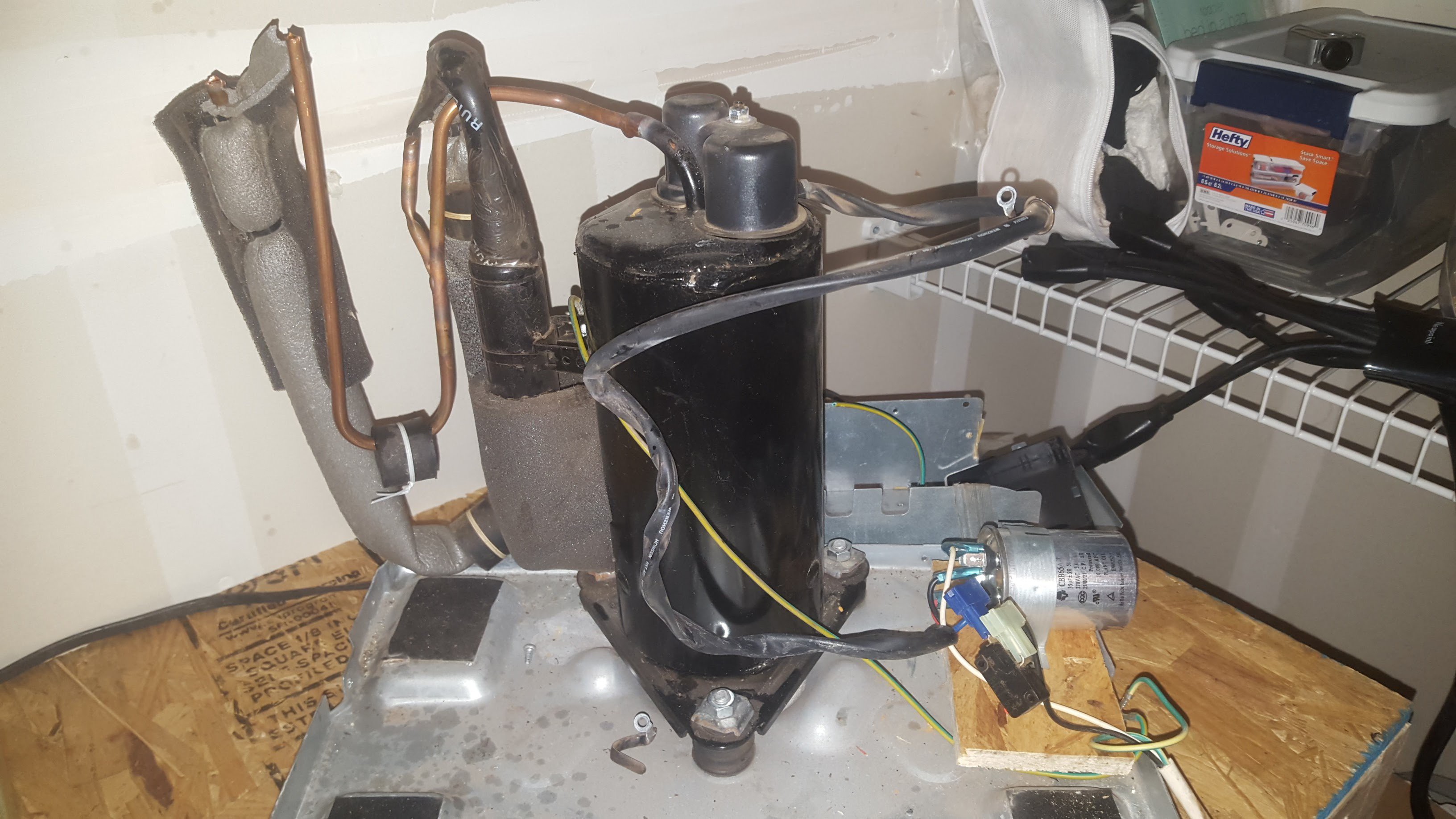
    Work has still been busy, it's been tough to get time in my garage lately. However I did manage to get an old de-humidifier taken apart, I'll be using the the compressor as a makeshift roughing pump. I got it all wired up, the pump starts and runs great. I used instructions from here: http://www.belljar.net/refrig.htm

    Next I need to build a small chamber and see how low this free pump can go. I'm hoping for about 1 Torr. I have a small, decently thick aluminum plate, and I'll place a jar on top of that, upside down. Anyone have ideas for how to seal a glass jar to the aluminum? I'm thinking I'll polish the aluminum real good and start with a scrap of rubber from a bike tire. (this is just for the rough vacuum chamber, no high vac stuff needed here yet). Other thought is to use a bead of silicone caulk. Thoughts?

    Also, I thought of another neat way to "measure" the vacuum inside. Partly, @DeepSOIC wisely pointed out that I'm likely overreaching with my "optical vacuum measurement" idea (see the last post). Partly, I've just always wanted to see if I could build one of these radiometers. I tried when I was 7 years old, but didn't realize you needed a vacuum to do it. Anyways, according to @Ben Krasnow these things start spinning in the millitorr range, about the right vacuum I think I need to make the discs work. My junk pile roughing pump will probably not get down low enough to make it spin well, but it's worth a shot. So, this would be a VERY crude but hopefully super accessible way of measuring the vacuum in both the rough and high vacuum chambers.

    Put one radiometer in the rough vacuum, and if it spins then you've got a good starting vacuum. Put a second one in the high vacuum chamber. If it stops spinning (while the rough vac radiometer keeps spinning), then you've got better than 6x10^-4 torr. Not exactly a "high" vacuum, however for a proof of concept to see if this whole disc idea has any promise at all, it's a start. And I can build these with aluminum foil, a sewing needle, a magnet, and black spray paint. I think...


  • Passive magnetic bearing prototype. Needs work.

    Keegan Reilly03/30/2016 at 17:21 1 comment

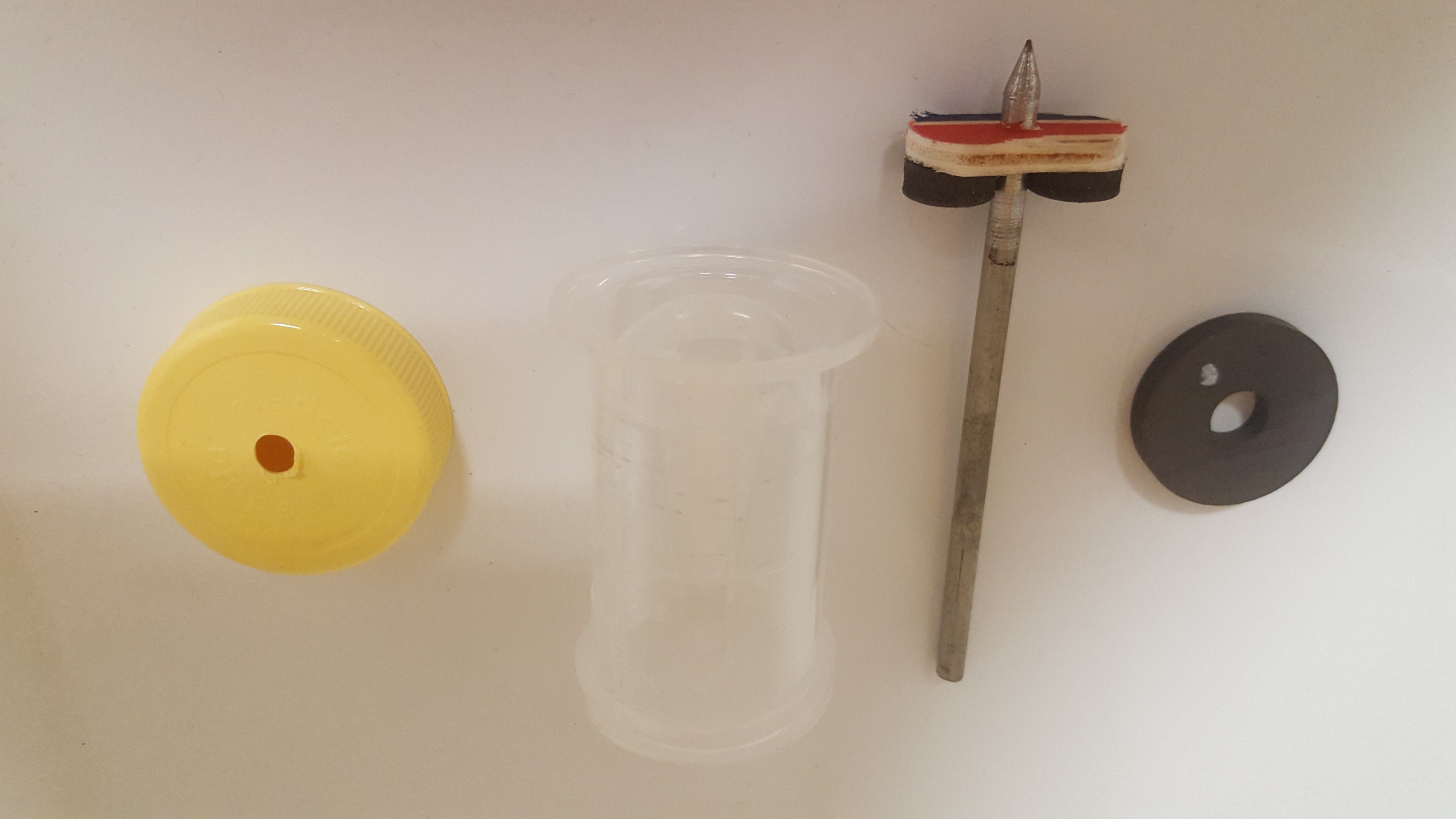
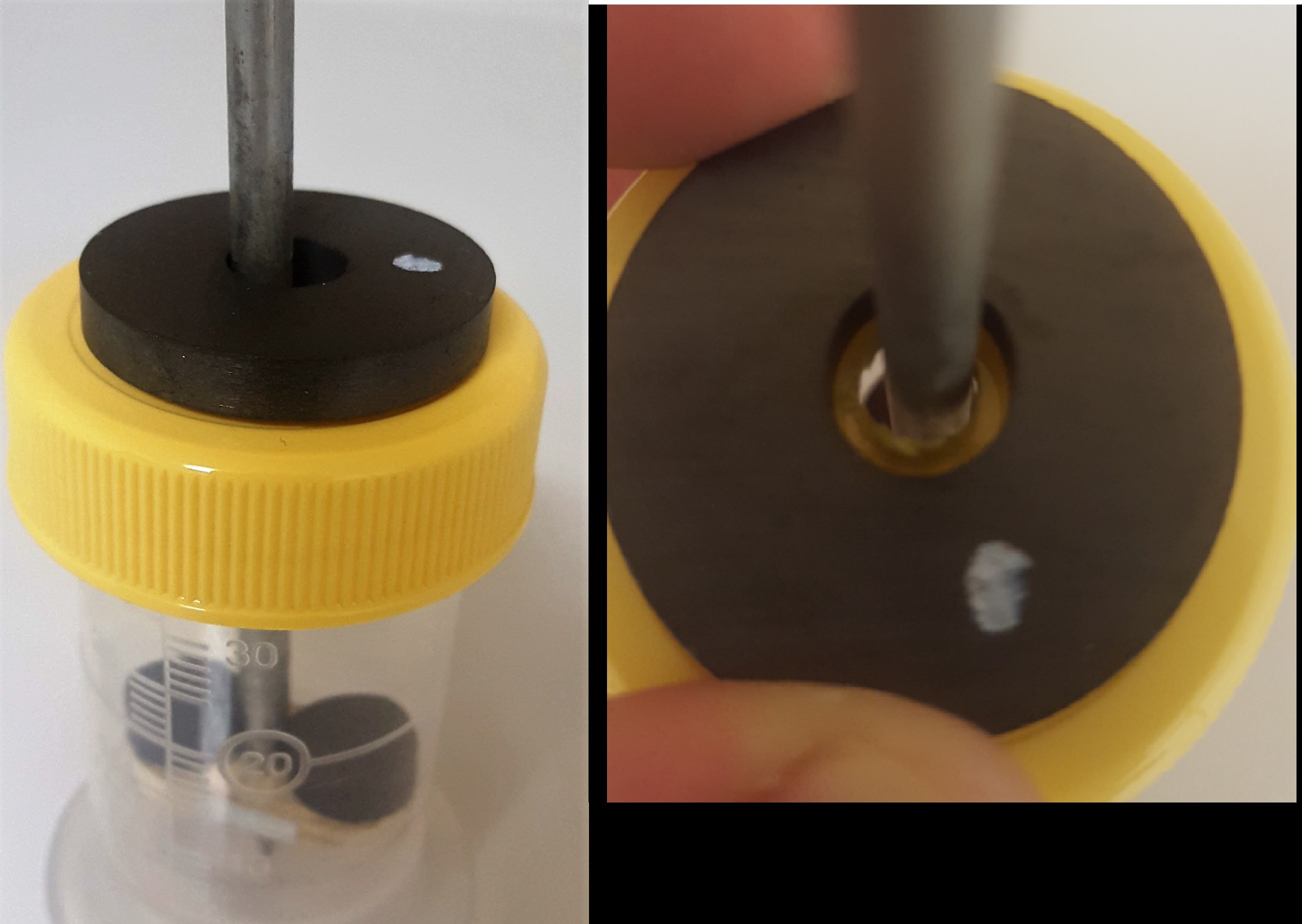
    So I finally built something! It's just a crude device to test the magnetic bearing idea. Doesn't work very well, but was useful to guide the design further.

    It all goes together in the little plastic bottle. Needle bearing works well on the concave bottle bottom, but would spin much better I think if it was against glass and not plastic. And if I made the tip sharper. The main problem is the magnet sucks the axle over too forcefully when it's stationary, so the axle rubs against the yellow cap's hole too much. I was just using my fingers to spin it so far, and was never able to get it going fast enough to even see if the magnetic bearing thing would work.

    What that means for the pump is that we would either need a decent mechanical bearing (i.e., not just a plastic ring) small enough to hold the axle away from the magnet, but large enough to allow the axle to spin freely when it get's up to speed enough for the passive magnetic effects to kick in. Part of the point of the magnetic thing though was to reduce complexity and avoid having to source special bearings, and worry about the grease in high vacuum.

    Another option I discovered though while messing around with it is to simply hold a magnet about 1/8 of an inch above the top end of the axle. It keeps the axle upright without touching it, and allowed me to get it going very fast just by blowing on the lower horizontal bar (I was just holding the axle outside of the bottle this time, holding the magnet above. Any old magnet would work for that, it wouldn't have to be a ring magnet or anything.

    A second option would be to make a "active" passive bearing, by using a solenoid coil instead. Then it could be turned off until the axle got up to speed. But that requires power to get inside the chamber somehow, whether through pass throughs or more coils.

    A third option would be a combination. A permanent magnet, with a coil around it that cancels out the magnetic field of the magnet until the axle got up to speed. Then the coil could be turned off, power removed, and the chamber cover set in place. That sounds complicated to me though.

    I'm thinking the first option (magnet held above the axle) is going to be the best.

  • Vacuum measurement

    Keegan Reilly03/22/2016 at 22:04 7 comments

    ***UPDATED 1 May 2016***

    I've decided to shelve this idea, some wise people pointed out a lot of problems that would be difficult (impossible?) to get around. Instead I'll be using a Crooke's radiometer to get a rough idea of how the vacuum is doing. See later project logs. Leaving the original post here for posterity.

    **************************************************

    ORIGINAL POST:

    First of all, I wanted to say thanks to everyone who followed/liked my project, and especially thanks for the comments and ideas you've shared with me. A lot of this is way out of my normal area of expertise, so I'm learning a lot along the way.

    This post is about finding a way to measure the vacuum, so that we have some way of tracking the pump's performance. There are lots of ways to do this, many of which could be done pretty cheaply. All require some sort of electrical pass through though, and to give myself the highest chance of building a working chamber I've been on the lookout for ways to eliminate those wherever I can. I had the idea of using a laser interferometer with one path shining through the vacuum. As the vacuum increased, the path length would change slightly, and might be able to be picked up. So I did some googling, and ran across an even simpler idea here (pdf). All of what follows comes from that paper, so credit is due to [Hasan Fakhruddin] for coming up with the idea. I'll rewrite it here in my own words so I can expound a little.

    Here's the setup: shine a laser through the glass vacuum chamber into a diffraction grating placed inside. After the laser passes through the grating and the other side, look at where the 1st order beam lands on the wall. The beam will be deflected varying amounts depending on the index of refraction of the near vacuum inside. The difference in deflection angles is very slight, so we'll have to find a way of amplifying the signal. Not sure yet if this will be possible. The change in deflection angle may be less than the beam width of the laser. But it's worth a shot because it has some distinct advantages:

    1. No pass throughs required at all. Just need a transparent chamber wall.

    2. Minimal materials required. Laser pointer and an old CD-ROM is about it. And a wall. Might need some mirrors.


    Here's some numbers to get an idea of how realistic this is. Here's the deflection equation, from the paper cited above:

    I happen to have a 532nm green laser pointer on my bench, so I'll run some numbers with that. I put a small excel file in the project documents section if you want to try these calculations with your own materials at hand. If we use an old CD-ROM as a diffraction grating, that gives us 625 lines/mm, or

    d = 1.6x10^-6.

    Lambda is 532x10^-9 m for air, and 532.15428x10^-9 m for vacuum.

    With M=3 (third order beam), theta (air) = 85.947 degrees, and theta (vacuum) = 86.190 degrees. So dTheta is 0.242 degrees. This is the total width of our measurement "signal" if you will. If we reached perfect vacuum, the beam would move .242 degrees on the screen. So, not much to work with, but we might be able to amplify it. I'm open to ideas. Putting the screen really far away, or bouncing it off a mirror that's really far away and back to a screen close to me is one option. Putting the screen at an extreme angle to the laser is another option, so that a small change in angle moves the dot a large amount across the screen (super simplified sketch below).

    Of course this also means the beam dot will kind of "smear" across the screen, it might be pretty wide, and hard to make a specific reading. I guess all I can do is try it!

    A quick note on selecting materials. In terms of wavelength or diffraction grating lines, more is not always better. The real goal is to get the deflection as close to 90 degrees as possible, without going over. That seems to maximize dTheta. The wavelength of the laser and the lines/mm of the grating have to be balanced to hit that. Also, if you can get the 1st order to be close to 90, vs. the 2nd...

    Read more »

  • Turbopump V 0.2 - Single stage lives again!

    Keegan Reilly03/20/2016 at 06:11 9 comments

    Alright, when we left off 4 months ago, I had been thinking we'd have to use multiple stages to reach our goal vacuum. However, the seals between stages were going to introduce a LOT of complications. I think. I didn't build anything, so far this is all just intuition. The other development is that I learned, thanks to [DeepSOIC], that discs tend to warp badly at high speed. He graciously proved experimentally that this warping is not an issue in rough vacuum, and the discs will spin smoothly and easily. See discussion on project page if you're interested. This does mean that a rough backing pump will be required just to get our disc pump up to speed safely. It's not the end of the world, decent backing pumps are like $100 at Harbor Freight, and can be found for free in old air conditioners.

    4 months ago I also mentioned I thought I had a way to get back to a simple single stage pump design. Here it is.

    The multiple stages was originally predicated on assumptions about the compression ratio of each stage, given a specific outer edge speed of the rotating discs. The max speed we're realistically (safely?) going to get is about 300 m/s with aluminum. At best. That gives a 1.6 compression ratio, 14 stages to a rough vacuum. However, as [Comedicles] astutely noted, the notion of pressure in the typical sense is basically meaningless when describing the flow of gas molecules at high-mid vacuum. There is no boundary layer, and the pump's operation can be better understood kinetically. As long as the mean free path of the molecules is larger than the gap width between the discs, they will not interact with each other in any "pressure gradient" producing way. They will simply (mostly) bounce between the two discs, picking up energy and gradually moving outwards.

    Here's the key. If our roughing pump can bring the pressure low enough, and our discs are spaced closely enough, the pump will work. How low of a vacuum it will produce is more a function of how quickly it can move molecules to the outer edges, and what kind of chamber outgassing we're dealing with. If anyone knows how to do that kinda math I'm all ears. It'd be pretty cool to run a simulation of the particle kinetics.


    Here's the new design, with a few numbers thrown in to make it sound more real.

    1. Get a nice donut shaped cookie cutter from the kitchen, a cutting board, and a roll of aluminum foil. And some kind of thin star shaped cookie cutter too. Not sure if those exist yet.

    2. Stack a bajillion alternating donuts and stars until we get about an inch thick total. The donuts are the discs of course. The stars act as hubs, spokes, and spacers between the discs.

    3. Mount this mess to a small aluminum rod I got from Lowe's, stuff it inside an empty pickle jar, add a motor, and we have a pump! Hey, this is HACKaDay, right? haha. In all seriousness...

    Roughing pump pulls chamber down to 100 Pa. The Harbor Freight pumps are rated down to 10 Pa, but let's assume that with the disc pump chamber and tubing and everything attached we only get 100 Pa. That put's the mean free path of air at .07 mm. Width of standard household aluminum foil is .016 mm. Perfect. We can use aluminum foil as both the discs and spacers.

    That covers the axle and discs. Next:

    Bearings: The bottom we can simply file the aluminum axle to a point and set it on a concave piece of glass as a makeshift needle bearing. I did actually try this, it works. Didn't try it at 60,000 RPM yet though... At the top, we can use a hollow cylindrical magnet. It might work like an electrodynamic bearing, I hope.

    Motor: This will be a rudimentary, horribly inefficient, brushless DC motor. I think that's the easiest way of spinning this thing without creating the need for extra seals or electrical pass throughs and craziness (i.e., sources for leaks). The bottom disc will not be foil, but actually 3D printed PLA or maybe machined aluminum disc with 3 spots to place strong permanent magnets. Directly below, but OUTSIDE the chamber...

    Read more »

  • 2016 Hackaday Prize! And update...

    Keegan Reilly03/16/2016 at 02:40 0 comments

    So just in case anyone is still following this project, here's a quick update. I had to relocate across the country for work and medical reasons, so tinkering and projects had to be shelved for about 4 months. The chaos is starting to subside now, and with the launch of the 2016 Prize it's time to dust off this vacuum pump idea and maybe actually build something at last. I'm not going to beg you for likes. If you think this project deserves one go for it, if not there are tons of other great projects out there. But be sure to browse the list of entries and throw your vote in somewhere. I'm open to more contributors too if this idea really catches your eye.

    On the technical side of things, I've had some hopefully useful ideas in the interim. Watch for some posts soon about how I plan to build the motor and discs, as well as the overall plan of attack for the build. It's going to have to be in several incremental stages, with specific experiments along the way. I also have some ideas on alternative, optical methods of measuring a vacuum that could be easier and cheaper than current sensors. Lastly, I scavenged an old compressor off a broken dehumidifier, it should make for a half decent backing pump. Here goes nothing...

  • Exploding disc test 1 (failure)

    Keegan Reilly11/03/2015 at 01:54 6 comments

    This test was a hack in every sense of the word. I just wanted to try spinning something for fun, so didn't bother taking any video (it wasn't very exciting in the end). I will try to describe what I saw, there were some interesting things to ponder.

    I began with a crudely cut disc of regular paper. It was crudely cut because I couldn't find my protractor or compass right away, so just folded it diagonally about 5 time then cut the corner off with scissors. It was pretty close to circular, but had little lobes on the edge. I don't think it mattered as much as I thought it would. About 8.5" in diameter. I duct taped this to a cutting wheel on my Dremel and turned it on.

    First test at 5k RPM it spun beautifully. Despite the folds and creases and poor cutting job it flattened out instantly and felt very smooth. Looking at it edge on it formed a nice thin edge, the forces flattened and stiffened the disc.

    Then I gradually increased the speed and it got much worse about 10-15k RPM. The disc was wobbling or warping or something. Too fast to see, but looking at it edge on, the blur had widened to about 1/4", and I could feel some turbulence.

    From just this info it's hard to tell whether this was due to my poor mounting system of duct tape or due to the inherent physics of the system. On subsequent tests with the same paper, I was never able to reproduce the smooth flat spin of the 1st test.

    Once the turbulence started I hit another snag, the Dremel maxed out it's power at only about 15-20k RPM. I tried running it faster but it refused to go. I didn't have an RPM gauge hooked up (I said this was a quick hack!), but I could hear the RPM change quite clearly in the lower ranges. Beyond 20k on the dial and the motor didn't change its tune.

    This was pretty dissapointing, I had really wanted to make something explode. I really thought paper wouldn't take much at all. Oh well. I have an old unused vacuum cleaner I may take apart and scavenge, I hear those have pretty fast motors. I'll find my compass and cut a proper smooth disc too.

  • One more multi-stage CAD drawing

    Keegan Reilly10/30/2015 at 03:26 2 comments

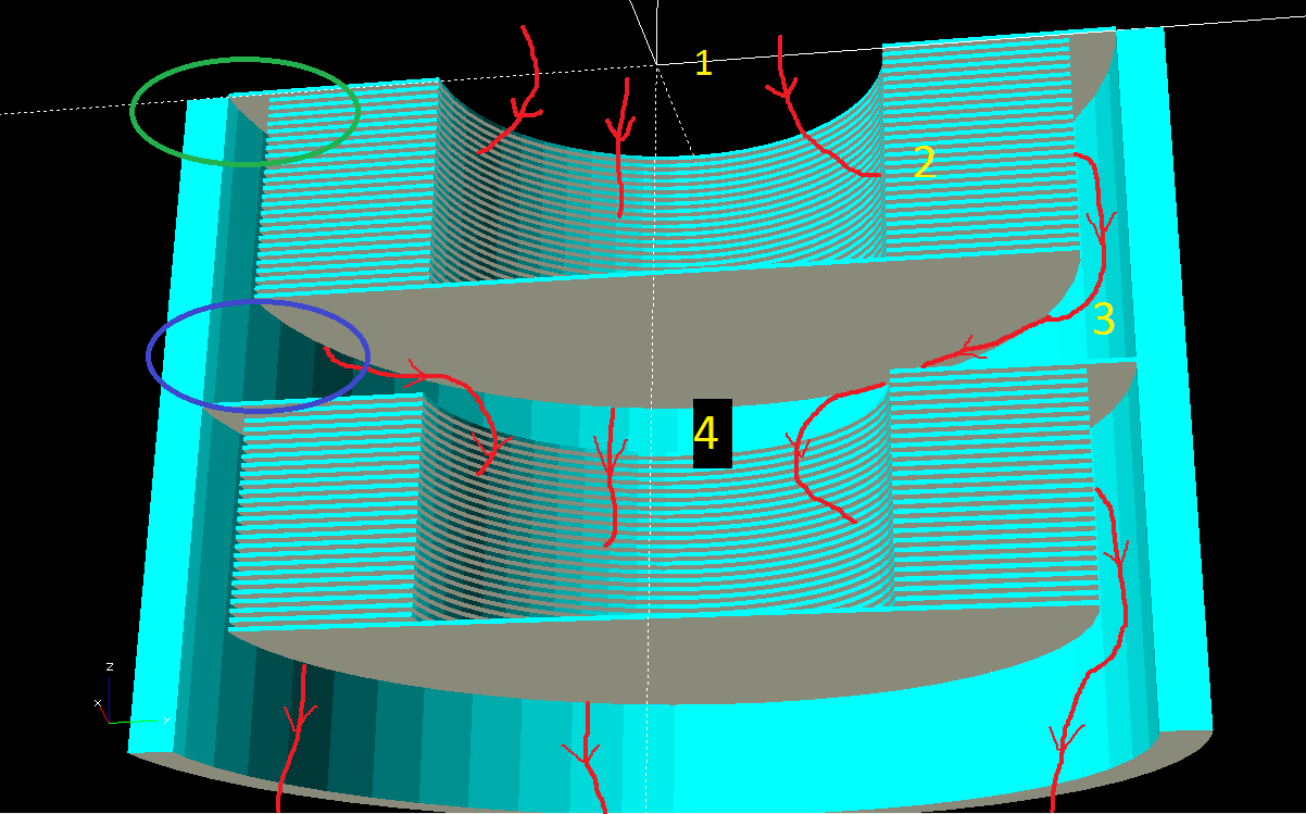
    Here is a more detailed render of two stages of a disc pump:

    Red lines are hypothetical air streams, minus lots of spiraling for simplicity.

    1. Air enters from the vacuum chamber

    2. Passes into the thin gap in the discs, where it get accelerated rapidly and flung towards the outside

    3. Air exits the discs at hopefully somewhat higher pressure, and follows along the stationary wall, where it begins slowing down.

    4. Once it has lost enough energy the air makes it's way to the center intake hole of the next pump stage.

    Two problem areas I foresee:

    Green oval: The seal between the intake disc and the wall. This disc is the main barrier between the different stage pressures. Considering this disc is also rotating at high speed, I have no idea if it is even possible to make that be a halfway decent seal. Also, this intake disc must be a slightly larger radius than the other discs, making it more susceptible to hoop stresses and explosion. Basically, the rotational speed will be limited by this disc, but the compression limited by the smaller discs. Perhaps the disc-wall gap could be gradually varied, increasing from top to bottom?

    Purple oval: Here the air has been given high kinetic energy (speed) from the discs, but must convert that into pressure before it can slow down and enter the central hole in the next stage. In normal centrifugal pumps this is done by the "diffuser", basically a finely tuned set of stator blades that slow the air down again. I had hoped to avoid the construction of blades due to their complexity, relying on friction with the outer wall to slow down the air. I have no idea how well this will work however. It could work fine, or the air might generate a bunch of heat from the friction. I understand that different diffuser design can do this "kinetic energy to pressure energy" conversion with various efficiencies, and I'm guessing the inefficient ones generate more heat and less pressure? But this is just my very uninformed reading of the Wikipedia page on centrifugal compressors. Any aerospace engineers reading this that might have some ideas? Do you think I'll need some kind of stator vanes in between stages?

    I have one more design idea for a single stage version that would avoid all of these issues, that'll have to be tomorrow's write up.

  • Simple CAD render of multi-stage tesla pump

    Keegan Reilly10/29/2015 at 04:08 0 comments

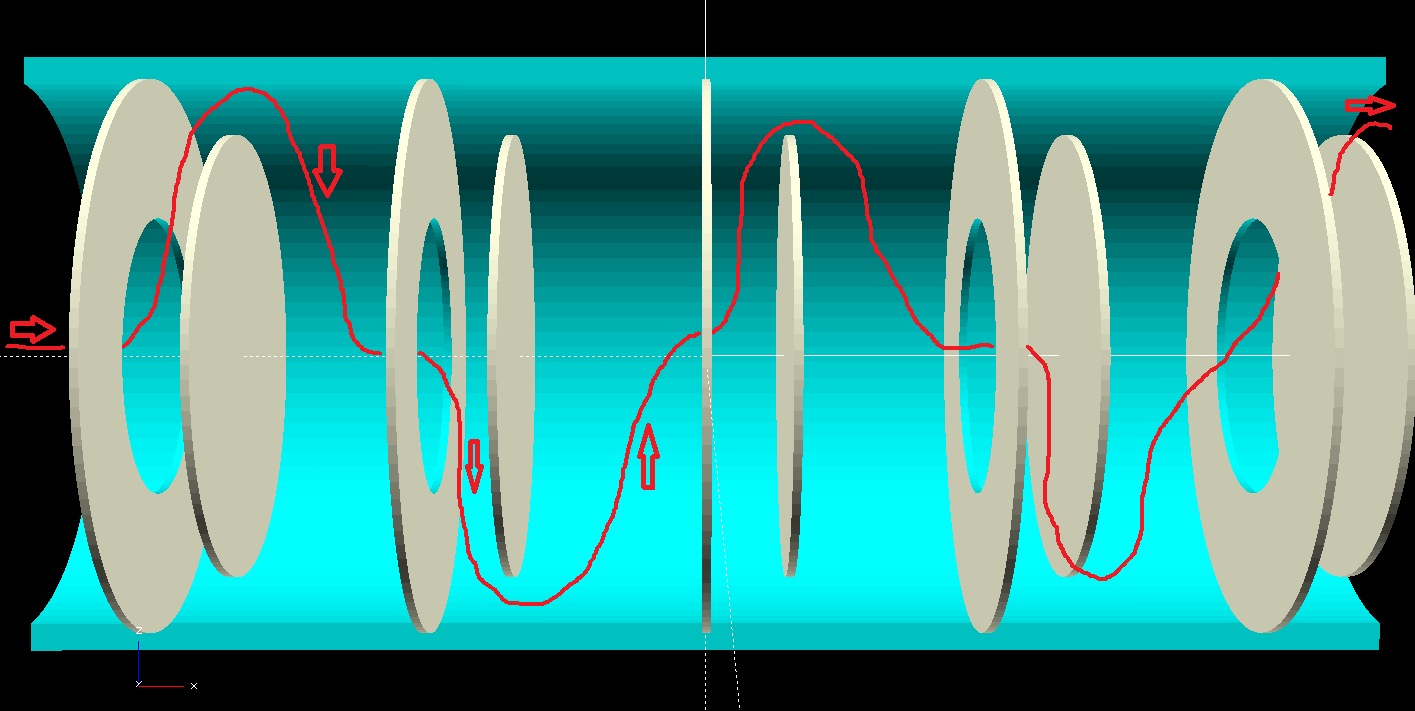
    I learned OpenScad tonight! Thought I'd try out making an ultra-simple model of a 5-stage disc pump. I drew in some red lines to show the path of the air molecules through the pump. This is massively simplified, and the spacing between the discs has been wildly exaggerated for clarity. In a real pump the discs would need to be MUCH closer together to be effective at all. Additionally, this render just shows one hollow disc per stage. Many more hollow discs could be added adjacent to one another within each stage in order to increase gas throughput.

View all 14 project logs

Enjoy this project?

Share

Discussions

excitedbox wrote 04/05/2021 at 03:56 point

Since this project seems to be dead, anyone interested in high vacuum pumps on a diy budget check out https://diyvacuumtubes.com/steampunk-diffusion-pump-t14.html. There are at least 2 other designs on the forum as well. This one is a cocktail shaker and some funnels.

  Are you sure? yes | no

excitedbox wrote 07/27/2019 at 06:01 point

If you counter rotate the spinning disc and the stationary one does it cut the speed you need in half? Could rotate the tube one way and the center shaft the other and attach the discs alternating to the shaft and tube.

  Are you sure? yes | no

eduardoriobrasil wrote 02/05/2017 at 18:40 point

Why not develop an automated Sprengel pump using Arduino to control the manual tasks? Sprengel pumps were used by the end of 19th century and are capable of dealing with 1mili Pascal.  See wiki on that subject. Dealing with Hg demands care and conscious use, but costs are very low and adequate for many DIY experiments. 

  Are you sure? yes | no

Ardutronic wrote 02/11/2018 at 12:12 point

The problem with Sprengel pumps, apart from the mercury, is that they're very slow, and one of the reasons he decided to build a turbomolecular pump is speed.

  Are you sure? yes | no

Raleigh wrote 05/17/2022 at 20:38 point

This isn't an inherent limitation of Sprengel pumps. They can evacuate large volumes quickly but are highly dependent on the flow rate of the mercury. https://www.chemistryworld.com/opinion/classic-kit-sprengel-pump/3004941.article

  Are you sure? yes | no

MTO wrote 04/11/2016 at 15:02 point

Hey! I want to donate some OpenSCAD to the cause! I occasionally remember to follow the forum on the metalicarap reprap, and somewhere in there, someone made a comment about how roots blowers are expensive and hard to design. I'm dubious. Step one is to 3d print something. Which I did. It doesn't spin very well, so I haven't tried using it as a pump yet, but it seemed to mesh OK.

... and I'll actually add a file once I figure out how to.

  Are you sure? yes | no

Keegan Reilly wrote 04/30/2016 at 13:09 point

Sweet! I'd be curious to see it, thanks!

  Are you sure? yes | no

nonappleuser wrote 04/10/2016 at 19:50 point

i like the electrodynamic bearing idea from what I've seen it seems easy enough to make ( at least in theorie https://en.wikipedia.org/wiki/Electrodynamic_bearing) and you would get levitation and self centering in one go so no contact and no friction. i wonder if you could make a frankenpump with some added radial blades (like in a radial blower) to eliminate the need for a roughing pump?

  Are you sure? yes | no

Keegan Reilly wrote 04/30/2016 at 13:08 point

Good thought on the radial blades.  I'm thinking about adding some thin spokes between the discs just for strength.  My main reason for the roughing pump at this point is that discs tend to wobble/distort badly at high speed in air, see the discussion with DeepSOIC below.  

  Are you sure? yes | no

John Stockton wrote 04/10/2016 at 14:28 point

This might have been covered before, but I would worry about the leakage sources of air around the sides and the ability of the bearings to maintain a pressure difference (particularly at high speeds, which is the domain of ceramic bearings).

Also on vacuum measurements, Thermocouple-style gauges are cheap ($60 on eBay) and relatively easy to drive/measure.  Lots of circuit examples available for a "531-style" gauge.

  Are you sure? yes | no

Keegan Reilly wrote 04/30/2016 at 13:06 point

Good points.  With my current design (not well documented/updated on the site yet), the bearings don't have to maintain any vacuum differential at all, for just that reason.  I agree, leakage past the discs is my main concern, but won't really know until I can get the prototype built.  Thanks for the tip on vacuum gauges, that's a lot cheaper than I'd thought!

  Are you sure? yes | no

Eric Hertz wrote 04/10/2016 at 08:00 point

Congrats on the blog-writeup!

  Are you sure? yes | no

Keegan Reilly wrote 04/10/2016 at 12:56 point

Thanks!  It was a nice surprise when I woke up this morning!  All the interest is getting a bit intimidating though, I guess I need to actually build something now, haha...

  Are you sure? yes | no

PointyOintment wrote 03/20/2016 at 06:59 point

While reading through the past project logs to catch up (having just started following this project), I came upon the term "molecular drag vacuum pump", which I had to look up. While searching about that, I came across some things you might find interesting (if you haven't already read them! (And if you have then others might find them useful for background.)):

Sorting Out the Turbo, Drag, and Turbo/Drag Pump Family suggests this is more of a molecular drag pump than a turbomolecular pump, but I think that only holds if one doesn't consider a Tesla turbine a turbine.

Mechanical Vacuum Pumps slide deck contains an overview of many different vacuum pump types (as well as some bearings), including an interesting diagram of a turbo/drag hybrid with the drag half being multi-stage Gaede, which looks like it might be similar in concept to yours.

A New Molecular Pump [starts on page 10] overviews the three main molecular drag pump types (Gaede (1913), Holweck, Siegbahn) and introduces the then-newly invented turbomolecular pump.

- Agilent TwisTorr is a turbomolecular pump backed with what they claim is a centrifugal pump but looks to me like an inverse Siegbahn one:

History of Vacuum Devices [p. 7 (287)] gives the diagram of the turbomolecular pump from A New Molecular Pump as a diagram of Gaede's 1913 pump.

Biltoft, Benapfl, Swain Ch. 10 shows Gaede's pump (though gives a date of 1912), along with Siegbahn's and Holweck's without their names.

  Are you sure? yes | no

Keegan Reilly wrote 03/21/2016 at 01:44 point

Thanks for the links!  I agree, in this case the line between "molecular drag" and "turbomolecular" pump is grey when considering the Tesla style.  I'm going with "turbomolecular" because it sounds a lot cooler to me :)

  Are you sure? yes | no

[deleted]

[this comment has been deleted]

Keegan Reilly wrote 03/20/2016 at 02:47 point

Thanks for following, I'd love to hear more of your thoughts, sounds like you know a lot more about this stuff than I do.  Safety is definitely something I'm thinking about.  For at least the first prototype, I'm actually planning to make the rotors paper thin, hopefully out of aluminum foil.  This should minimize the kinetic energy of each disc, should it explode.  

Second, the first experiment I have planned when I get a rough vacuum chamber and motor built is to purposefully spin some discs up past burst speed (without anyone in the room of course) just to see what happens.  A: it would be good to know if exploding foil can get through vacuum chamber walls, and B:  experimental verification of theoretical burst speed.  This way I can design the pump to operate with a comfortable safety margin under the burst speed, and I can design adequate safety precautions if a shock load causes rotor rupture even at that "safe" speed.  

  Are you sure? yes | no

PointyOintment wrote 03/20/2016 at 07:00 point

Another thing to keep in mind is that if one disc fails, the whole rotor will lose its balance and likely explode (or maybe bend the axle) soon after. Each disc will probably need to be balanced well.

  Are you sure? yes | no

Keegan Reilly wrote 03/21/2016 at 01:53 point

Yeah, I honestly haven't thought much about balancing the rotors yet.  I'm sure it will be an issue, not sure how big of one yet.  Though I think one disc could fail without hurting the others, if it flies straight out and has room to collect by the chamber walls.  This would be a key difference from normal turbo pumps, where I presume rotor failure starts with one single blade, throwing the rotor out of balance.  The loose blade also has nowhere to go (they require pretty tight tolerances with to the housing walls), so it joins the other blades/rotors.  Hence the "blade salad".  In theory, if a disc ruptures it will look more like those videos of exploding CDs, where the whole thing let's go at once.  No time for it to be out of balance.  But that's all just theory in my head.  Someday I'll try it out for real :)

  Are you sure? yes | no

Steve Shaffer wrote 03/19/2016 at 20:53 point

hey buddy, a friend made a tesla turbine that works, and is easy to machine, would be easy to make and stack a lot. I can get him in touch with you.


  Are you sure? yes | no

Keegan Reilly wrote 03/20/2016 at 02:48 point

That'd be awesome!  I'd love to hear about his experiences.  That's an awesome CAD render btw.  For my design I'm actually hoping to minimize the machining.  Right now I'm thinking the initial prototype blades will simply be cut out of aluminum foil.  I need to make a LOT of them...

  Are you sure? yes | no

Comedicles wrote 03/19/2016 at 18:41 point

I love the idea. You are absolutely right than some good high vacuum gear opens up a lot of areas to explore. Here is, I believe, the McGuffin: "no one except Tesla himself has attempted to use this style of pump for high vacuum applications". So, where is the boundary layer in a vacuum? Maybe that is why only Tesla tried it? He was very much a no-math intuition guy.

Turbo pumps I have seen all have turbine blades and they are not shaped like jet turbines or air pump or water turbines. There is no airfoil shape and there are no flow and pressure zones to work with in near vacuum. They are more like paddles and they actually swat the air molecules toward the next set of blades and eventually to the fore pumps. The pump's job is to increase the probability that a gas molecule or atom will be in the vicinity of the next pumping stage. Oil diffusion and mercury diffusion pumps work the same way but by blowing the pumping gas towards the exit and colliding with the air molecules, concentrating them a little in one direction. The gasses are bouncing around at, guess what, that's right, the speed of sound at their temperature (pressure doesn't matter and doesn't appear in the equation for speed of sound. The beauty of elastic collisions). So they all eventually get in the way of a blade.

I can picture that happens to some extent with the discs. When an atom (lets say Argon to keep it fat and simple) hits a spinning plate there is an elastic collision and it will pick up some momentum in the direction of spin and might or might not have more collisions before it reaches the edge. (The Argon atom at room temperature is going slower than your disk's outer edges before it gets hit). So yes, something interesting might happen, but not the boundary effect stuff. You need a kinetic theory analysis, which would not be that hard to do and well understood before 1900. Way beyond Tesla's abilities I suspect. He should have read Gibbs and later talked to Millikan - who had great respect for Tesla. More than one finds today.

Soldier on! Refurbished pumps from the semiconductor business (with a controller, which you need) are on eBay for, gulp, over $2000. Chip making uses lots of them for RTP or Rapid Thermal Processing which has pancake vacuum chambers and they want to pump down in seconds instead of minutes. Note: I would stay away from systems that were used in electron microscopy. Those folks use stuff in sample preparation that will make your corneas go opaque, so cleanup needs a special box and ventilation.

How about a source for Indium O-rings? Oh, and tubing made from "electroless" copper. Standard copper tubing made directly from electroplated smelting will never quit outgassing, or leaking helium if you use it to test. It has to have been melted and reformed in some way. I would have to refresh my recollection with the Googler. 

Silver-solder is the choice for joining copper or stainless steel. If you can manage it, preferably in an oven with a hydrogen atmosphere - no flux needed for that.

  Are you sure? yes | no

Keegan Reilly wrote 03/20/2016 at 03:42 point

Thanks for the thoughts!  I like your explanation of the kinetic action inside the discs, that is definitely how I understand it now (though not when I started this project, learned a lot the last few months).  The key I think is in keeping the disc spacing ultra close, such that the mean free path is less than the disc gap width.  This necessitates a roughing pump to have any reasonably build-able gaps .  I had hoped to avoid the rough pump, but I don't see a way around it honestly.  It's not so bad, they're only like $100 from Harbor Freight.  

I didn't realize regular copper outgassed so badly!  Thanks for that info.  For the pump construction itself I don't think it matters, since the chamber walls will only be at a rough vacuum anyways.  Only the central column in the middle of the discs will be at high vacuum.  However interfacing this pump to a high vacuum chamber is a HUGE problem I haven't begun to solve yet.  Thought about it a bit, far from solved.  To be honest, I think constructing the high vacuum chamber itself out of accessible materials may be more difficult than the pump!  Maybe that's a Hackaday Prize project for someone else.

A quick Google did turn up some electroless copper plating.  Looks simple enough?  I'm no chemist.  If you just plate a couple layers over top of regular copper do you think that would work to cut down the outgassing?  I guess all we can do is try it...

  Are you sure? yes | no

DeepSOIC wrote 12/14/2015 at 18:03 point

I'm wondering, if a labyrinth pump concept can be used for the purpose. See my #screw fan project...

  Are you sure? yes | no

DeepSOIC wrote 12/01/2015 at 21:20 point

Here it is!

When I was about to let some air in as it was spinning in vacuum, the motor heated to the point the PLA spacer started to creep, causing an accident. Glad that the chamber didn't implode, phew!

[wanted to post a pic here, but couldn't figure out how to do that]

  Are you sure? yes | no

Keegan Reilly wrote 12/01/2015 at 23:32 point

That's awesome, thanks for sharing!  So it  looked like just letting a little bit of air back in caused instant instability, to the point of flipping itself over.  Fascinating, and totally unexpected.  I agree, I think it proves that the warping effect is somehow aerodynamic.  Those are the best kinds of experiments! I'm thinking my disc pump will have to be housed in a rough vacuum chamber, evacuating a central high vacuum chamber.  

  Are you sure? yes | no

DeepSOIC wrote 12/02/2015 at 11:18 point

I want to stress it again: the flipover wasn't because of air. It was a coincidence. I did that before doing the video - nothing fascinating. The motor slows down quickly, and that's all.

This flipover happened because the plastic started to distort, causing massive imbalance, leading to strong vibration.

Unfortunately, the glass the desiccator is made of is ugly, so it's hard to see the details of what's going on inside.

  Are you sure? yes | no

Keegan Reilly wrote 12/03/2015 at 02:16 point

Ah, I understand now. In the first trial (before shooting the video), did you happen to notice the temperature of the motor after doing the test? I'm curious whether the heating happens as you let air in and the air resistance increases drastically or whether it is heating up slowly the whole time, and unable to cool itself due to the vacuum. Thoughts?

  Are you sure? yes | no

DeepSOIC wrote 12/03/2015 at 12:07 point

Well, I didn't do any tests on how vacuum/air affect heatup of the motor, but the motor is heating up seriously in both situations. Mainly because the amplifier drive is using only one set of coils of three available in the motor, making it inefficient. Second - the amplifier isn't driving the motor in a very efficient manner anyway, even not considering the coil usage. And finally, this motor's design speed is 7krpm or so, so I'm making it spin five times its design speed. So the bearings are going to generate much more heat than normal.. And the iron core too, because the frequencies are higher, increasing Eddy currents.

When I open the chamber after the tests, I always smell burnt wire. And the set of coils that I'm using, have changed color due to overheating.

  Are you sure? yes | no

TK wrote 04/10/2016 at 05:31 point

Awesome test. If you're looking to make the spinning of the disk more visually apparent, perhaps a strobing light will help? Many apps available for phones available and you could try it out. 

  Are you sure? yes | no

DeepSOIC wrote 11/29/2015 at 22:13 point

I did my test spinning stuff in vacuum!

The object was a 3.5'' floppy disk, attached to a hard drive motor powered by a special positive-feedback amplifier that can spin these motors to crazy speeds.

In air, I could only achieve about 15k rpm, and the disk started to become unstable at about 10k rpm.

In vacuum, it got up to 40k, and was going smooth as a whistle! The vacuum wasn't terribly deep. I don't have a gauge, but that vacuum pump tested on a different setup with a gauge, was giving about 6 Torr at best (essentially it's dead; it was providing something about 1e-2 Torr when new).

I gave up on CDs, because I could not spin them fast enough to start warping in air. Although I think, if I put it into vacuum, I can make it explode (but I won't, because that may cause the vacuum chamber to implode, and since it's made of glass - I don't want that to happen).

I can record a video if interesting.

  Are you sure? yes | no

Keegan Reilly wrote 11/30/2015 at 17:57 point

Awesome! Thanks for sharing!  That seems to indicate that at least some (all?) of the warping is due to aerodynamic effects, I totally didn't expect that.  It's good news from the vacuum pump standpoint.  A disc pump venting directly to atmosphere may not be workable then, but if it is enclosed in a chamber backed by a very rough vacuum, the materials strength may not be as crucial.  I'd love to see a video when you get a chance to take one.  I did take some video of my really crappy experiment a couple weeks ago, I've been meaning to post that too.  What I saw sounds very similar to your atmospheric tests as well, with a paper disc spinning nicely until about 10k-15k rpm.  Couldn't get it to go beyond that, my Dremel was too weak.  Time to build a  vacuum chamber... Thanks again!

  Are you sure? yes | no

DeepSOIC wrote 10/28/2015 at 12:56 point

Another interesting problem to consider. Rotating disks begin to warp spontaneously. Have you ever tried spinning a CD quite fast?

  Are you sure? yes | no

Keegan Reilly wrote 10/28/2015 at 17:53 point

That's a really good point, I have never tried that myself, was hoping to next week though when I get back to my garage!  Have you?  What happens?  Tesla's steam powered disc turbines had some bad warping issues which is partly why they never really caught on, I (and most internet sources) assumed that was due to thermal effects and poor metallurgy.  I guess we'll find out!

  Are you sure? yes | no

DeepSOIC wrote 10/28/2015 at 18:10 point

Yes I did try. I'm not sure what is causing the effect. It might be an aerodynamics thing...


Scroll the video to 8:00

  Are you sure? yes | no

Keegan Reilly wrote 10/28/2015 at 18:39 point

Wow, that's cool!  And terrifying.  YouTube wouldn't play the mythbuster's one for me, but the SlowMo guys did a nice video of it too:

It looks like a mechanical effect to me.  CDs are made in layers, polycarbonate then aluminum then protective laquer.  Each of these materials have different densities and tensile strengths, and will stretch differently under the same stress.  If one layer wants to stretch further than the other, or is undergoing increased centripetal forces due to a higher density, then it makes sense that it would warp pretty badly.  That's just my guess though, could be thermal too, outside of the disc heating up faster than the inside or something. 

  Are you sure? yes | no

DeepSOIC wrote 10/28/2015 at 20:43 point

Well, as for warping, I see two things that can potentially cause it.

One is aerodynamical: wind blowing over the surface of the CD creates waves, just like regular wind creates waves on water. Much stronger wind is needed, because of fixed wave propagation speed (unike water, where wave propagation speed and frequency depend on amplitude)

Second can be purely mechanical: If we split a CD into rings, the outer rings will expand considerably more than inner rings, because of higher centrifugal force. But since the rings are not split, the length has to be put somewhere, so it warps. But I'm not sure if it can happen.

So, to find out, one has to spin a CD in vacuum. I think I might be able to do that!

  Are you sure? yes | no

DeepSOIC wrote 10/26/2015 at 17:48 point

Hmm.

A little while ago I was considering building a 3d-printed turbomolecular pump. As a followup project to this:

http://forum.freecadweb.org/viewtopic.php?f=24&t=10590

After doing some rough math on maximum rotation speeds, the goal doesn't look unreachable.

  Are you sure? yes | no

Keegan Reilly wrote 10/27/2015 at 01:37 point

Wow, that looks amazing!  Even if it didn't give much compression, it's cool to see something that complex come out so beautifully on the 3D printer.  I thought about 3D printing a turbo-pump as well, but from what I've read most 3D printed materials are not very compatible with the high vacuum environment, they off gas too much.  I found a paper on it, could send you the link if you're interested.  If I remember right they said that only 3D printed sterling silver had enough dimensional stability and low enough off-gassing to be useful in a high vacuum.  That's why I started looking into disc type molecular drag pumps instead. 

  Are you sure? yes | no

DeepSOIC wrote 10/28/2015 at 12:49 point

Yes please! Send me the paper =) vv.titov@gmail.com

  Are you sure? yes | no

DeepSOIC wrote 10/28/2015 at 17:44 point

Thanks for the paper!

  Are you sure? yes | no

Keegan Reilly wrote 10/28/2015 at 17:49 point

No problem, hope it helps!  I had another thought.  Most of the pump parts aren't really "in" the vacuum chamber themselves, so you might still be able to get away with it even though they off gas.  Maybe whatever molecules off gas from the pump blades would just get sucked down and immediately expelled, so it "might" not be that big an issue.  I'm at a loss as to how to calculate that effect though.  Pfieffer Vacuum has some good stuff on calculating off-gassing rates for different materials, I suppose you could run those numbers for each pump stage and make sure they don't exceed that particular stage's pumping throughput capability. 

  Are you sure? yes | no

DeepSOIC wrote 10/28/2015 at 17:57 point

I took a glance into the article. It is about SLS 3d printing, which isn't something very common.

I was more interested in the common FFF stufff, like PLA, ABS, polycarbonate. I think PLA might be not bad, but its temperature vulnerability basically rules out any sort of high vacuum.

  Are you sure? yes | no

Keegan Reilly wrote 10/28/2015 at 18:55 point

Ah, good point.  I guess we'll just have to try the FFF stuff ourselves!  On the off chance this disc pump thing actually works, I'd be happy to test some samples for you.  A real 3D printed turbo-pump would be awesome, and it'd just be nice to know whether those other materials would work in vacuum or not. 

BTW your blower makes me want to learn OpenScad, it looks really powerful.  I used SolidWorks in college, but would like something more parametric.  Just downloaded it :)

  Are you sure? yes | no

DeepSOIC wrote 10/30/2015 at 12:31 point

I also sometimes think of learning OpenSCAD, but the amount of trouble I need to go through to make a relatively simple thing does not make me happy. That's why I'm using FreeCAD (which is more similar to SolidWorks than to OpenSCAD). I use my own branch of FreeCAD actually. The only reason I might go for OpenSCAD is if I need a deeply parametric model.

I'm not sure, but it looks like OpenSCAD can't output standard STEP files, it looks like being only capable of generating meshes.

  Are you sure? yes | no

Ben Krasnow wrote 10/25/2015 at 20:49 point

Thanks for mentioning me!  Don't worry too much about the math and theory.  Using math to optimize a design is great, but it's often not necessary to get a working prototype.  Turbomolecular pumps are often built as a combination of turbine and molecular drag sections.  The molecular drag section is very similar to a tesla turbine, and is usually built with slotted flat discs or as a cylinder with helical vanes.  Try searching patents for nice detailed drawings of how they are built.  Good luck!

  Are you sure? yes | no

Keegan Reilly wrote 10/26/2015 at 01:07 point

Thanks Ben!  Great to hear from you!  That's a really good point about just building something to start.  I needed to at least work through some math because to my knowledge no one has tried this exact thing before, so I need just enough math to come up with a design that will at least get me in the right ballpark.  I think I may run a couple of incremental experiments first though, which would be simpler and would help verify the initial maths.  Plus I've been out of town, and won't be back to my garage for another week, so in the meantime math is all I can do from my hotel room :)

Molecular drag pumps are really cool, and seem to be the closest thing to what I have in mind, minus the nicely machined grooved discs.  They are what make me think a Tesla Turbine might still be effective in the high vacuum range.  Pfeiffer says they are specifically designed with small channels to utilize molecular flow even at relatively high pressures. 

  Are you sure? yes | no

zakqwy wrote 10/23/2015 at 16:55 point

I spent too much time looking at turbomolecular pumps on eBay awhile ago. Looking forward to seeing where this goes. You've got some challenges ahead of you, no doubt..

  Are you sure? yes | no

Keegan Reilly wrote 10/23/2015 at 18:34 point

Haha, no kidding!  I've been working the math for a while.  Once I get it posted I'd love if someone smarter than me could check it.  I think it's possible according to the theory, but you never know till you actually build it.  We'll see!

  Are you sure? yes | no

zakqwy wrote 10/24/2015 at 14:50 point

@Ben Krasnow has experience with ultrahigh vacuum stuff in the DIY realm. Might be worth reaching out to him, I'm sure a DIY turbomolecular pump is something he's mulled over at some point or another.

  Are you sure? yes | no

Keegan Reilly wrote 10/25/2015 at 12:45 point

@Ben Krasnow is the man!  I've been watching his videos for years.  His electron microscope is still the coolest hack I've ever seen on here.  I'll definitely try reaching out to him, once I get more of my math and theory posted. 

  Are you sure? yes | no

Similar Projects

Does this project spark your interest?

Become a member to follow this project and never miss any updates