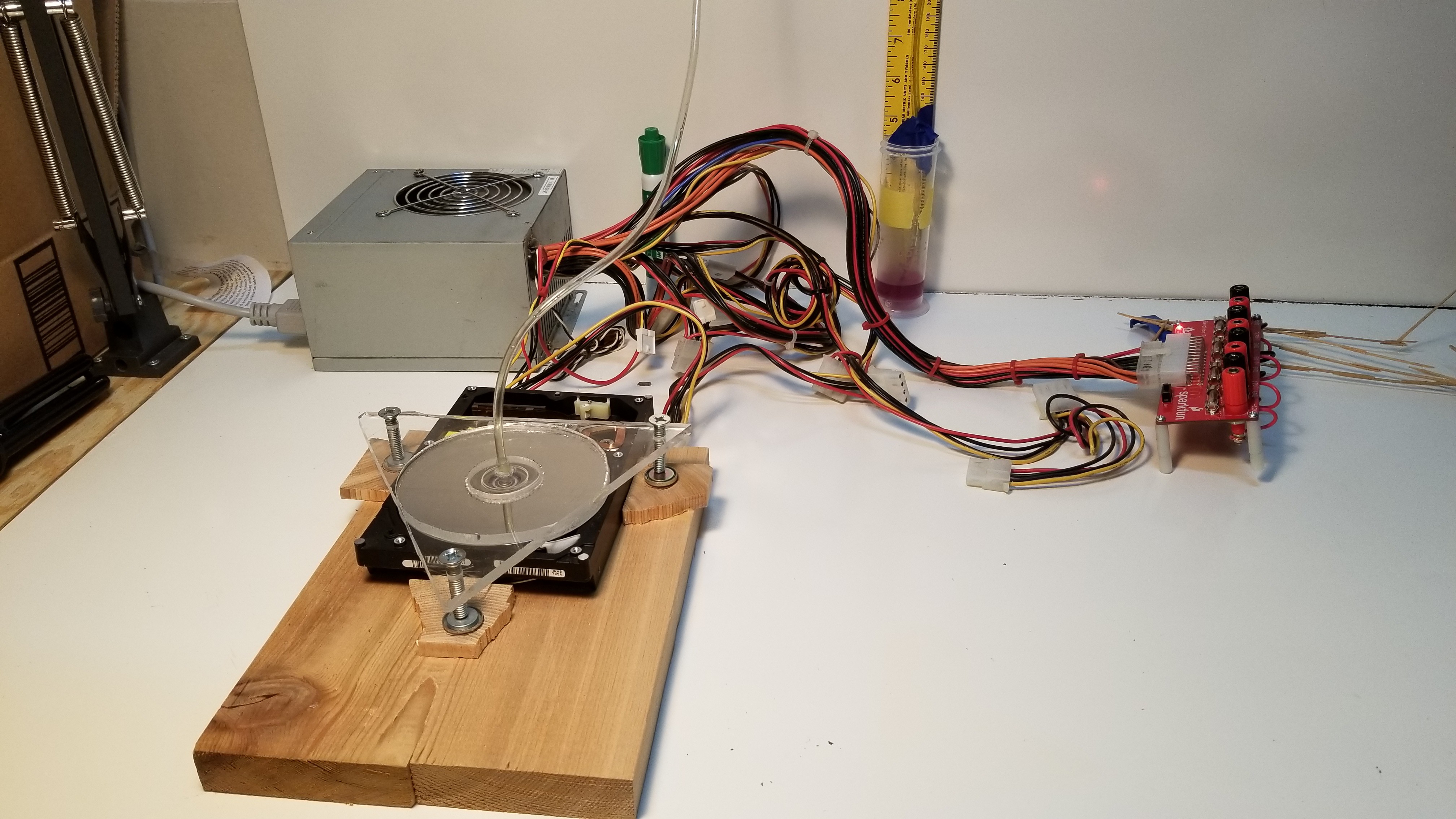
Welcome back folks! It's been a long time since I've been able to make any headway on this, had to wait a while to scavange just the right parts. I got a free PC power supply and some old hard drives, and decided to massively simplify the device in order to run some very initial experiments and verify my hypothesis. I did NOT expect this to approach anywhere near "high vacuum" or even what could be considered decent "roughing vacuum". This is a highly simplified device to test the relationship between gap width and peak pressure differential produced.
In brief, the device was far less effective than even my meager expectations had allowed. I may yet submit this to "Fail Of The Week." However, it did work well enough to show that a smooth rotating disc can indeed pull a slight vacuum against atmospheric pressure. To my knowledge, this has never been tested before in the literature I could find.
The Setup: Rotor, Stator, and Motor

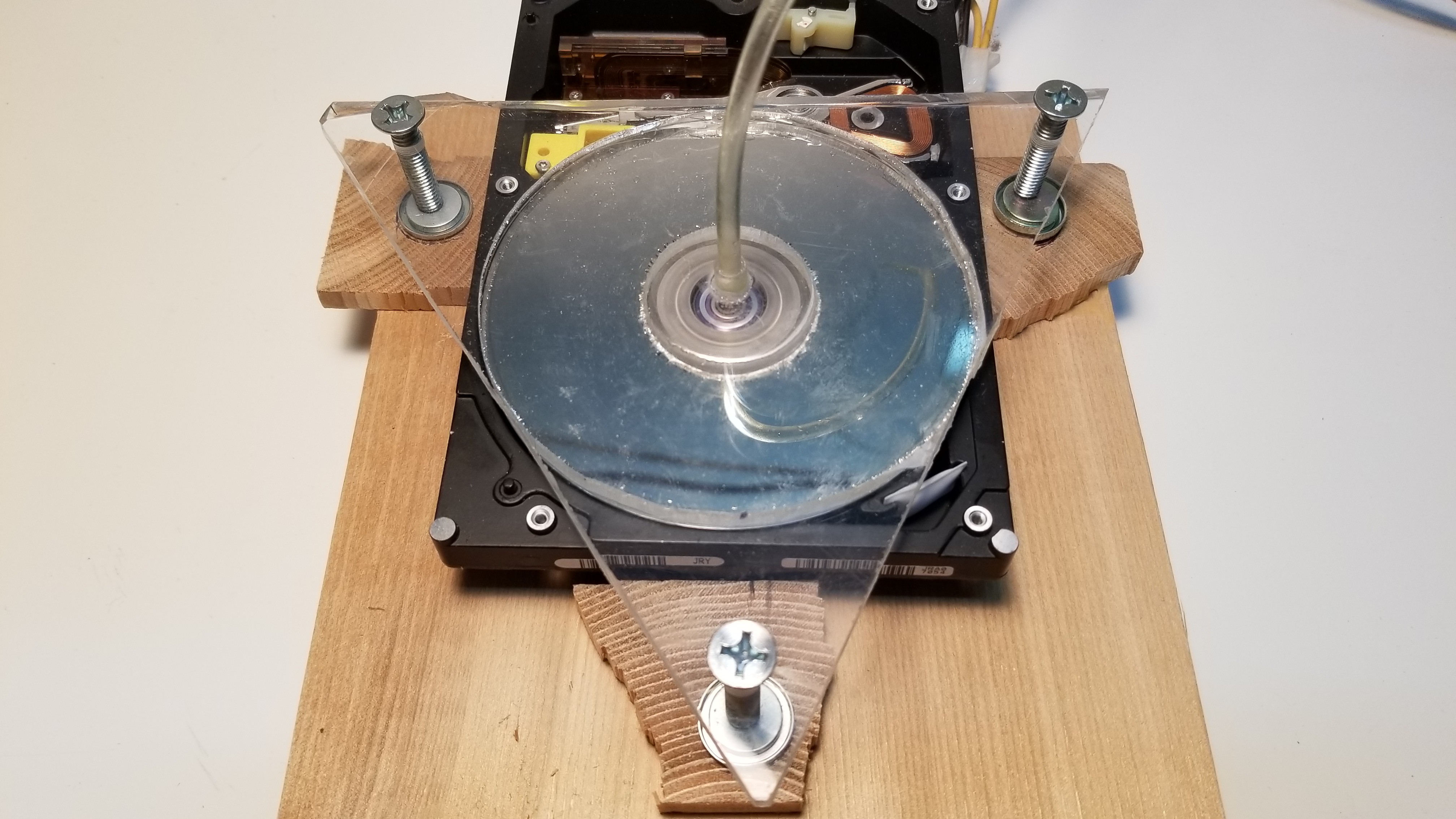
A HDD makes an ideal rotor, as it is perfectly balanced for high speed operation and perfectly flat to allow extremely small gap widths. For this experiment I am simply using the stock circuitry to drive the motor at its intended 7239 RPM. In future experiments I may attempt to make that speed adjustable. The stator is made of clear acrylic (eventually I hope to observe Newtons rings to fine tune the gap width and stator position), and also forms the bottom of the "vacuum chamber". It leads directly into the pressure measurement tube (center). The stator angle above the rotor is tuned by carefully turning the 3 point bolts to make it as parallel as possible. The bolts are fixed to the platform on 3 strong magnets.
The Setup: Pressure Measurement

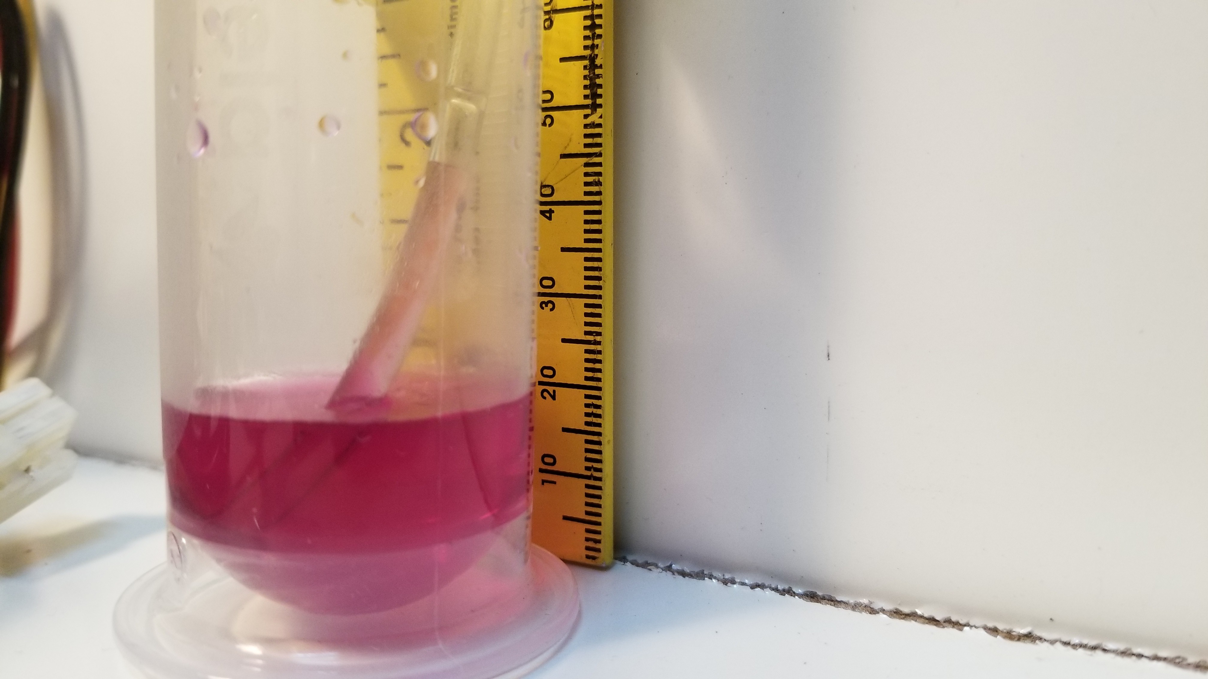
Pictured above is the best result I could get on my first day, 2.4cm of vacuous glory, barely 0.036 PSI below atmospheric pressure. Using a water column has several distinct advantages. It is super cheap, and requires no calibration, since the height of a water column is already a standard measurement of pressure differential.
Results and Discussion:
There were a number of problems with this setup, mostly due to it being hastily "hacked" together. This is Hackaday after all.
Problem 1: The acrylic stator was not perfectly flat. If I rested it directly on the HDD before turning it on, the acrylic could be rocked back and forth, so it was somehow bent lower in the center. This limited the minimum gap width I could achieve to no less than about .5mm.
Problem 2: The bolts are too wobbly. The stator had a tendency to wobble laterally, causing the center to crash into the raised center mount on the HDD.
Problem 3: My gap measurement technique was not accurate enough to get anything other than qualitative results like the above picture. It is working, but both the gap measurement and stator positioning are too inaccurate to extrapolate any sort of generalized functional equation of performance to guide future engineering efforts.
I will have to address these 3 problems before I can get more useful data out of this setup, but I do think there is more to be learned from it given those tweaks.
On the plus side, I have verified that Tesla type disc rotors can indeed work as (rudimentary) vacuum pumps, even at atmospheric pressure. Qualitatively, the level of vacuum produced (height of water column) did seem inversely proportional to the gap width between rotor and stator, as my theory had expected. Given those, it does seem possible to create a single stage high vacuum pump that can back itself to atmospheric pressure, given a smooth enough rotor/stator and tight enough gap width. At least we're finally out of the realm of pure theory.
Update as of 21 March 2018
I quickly sanded the acrylic disc flat, just to see if that would have any effect. It made for a remarkable increase in vacuum pressure, as I was able to get the stator and rotor much closer together before any part started rubbing on the other. I ran into another difficulty. I had previously relied on the HDD itself being held down by gravity. With the newly effective vacuum forming, it was enough to lift the entire HDD up, causing the rotor to crash into the stator. Once they became extremely close (and started touching), the motor got overpowered and began slowing down. Because of this, getting a solid stable reading of the resulting vacuum was impossible, however I estimate I saw at least 9-10cm of H2O (0.14 psi) briefly.
For more comparison/guesstimation, the disc radius = 1.9 inches, so disc area is about 11.3 inches^2. The HDD weighs 0.86 pounds. So at its peak, the pressure differential was at least as good as 0.86/11.3 = .076 psi. So I'm confident I hit somewhere in the ballpark of .076 to .14 psi below atmospheric pressure.
I think with this development I have reached the limits of what I can learn from this rudimentary setup. I will have to design and build a much more solid and precise platform before I can get any more significant or measurable pressures. I need to HDD solidly locked to the same frame as the stator, and I need a more precise Z movement. This version of the stator is much too wobbly.
Discussions
Become a Hackaday.io Member
Create an account to leave a comment. Already have an account? Log In.
check out this expired patent: US10/810,871 multi-stage dry vacuum pump for high vacuum applications. Adapted from Tesla’s US1,061,206 patent of may 6 1913
Are you sure? yes | no
Keegan, are you still working on this?
Are you sure? yes | no
I hope you are still thinking about this as it's an interesting concept.
Unfortunately the setup you're using in this post can't work, and it's actually impressive it was even able to pull a few cm of water of vacuum.
What you are trying to make is called a 'molecular drag pump', and the theory and design of these kinds of pumps has been heavily researched and documented. There is a lot of info on this, which it doesn't seem you've looked at. Read 'The Handbook of Vacuum Technology' by Jousten; he devotes a full chapter to analyzing these kind of pumps. The three main designs for this kind of pump are the Holweck, Siegbahn, and Gaede stages (all three have been used in various turbomolecular pump stages).
In short, you need several things for a molecular drag pump to be effective:
- The rotor speed needs to be of the same order as the speed of sound (much higher than you have here).
- The distance between stator and rotor needs to be of the same order as the mean free path of the gas (which for atmospheric pressure air is around 70 nanometers!). Commercial turbodrag pumps are often designed to be used in the millibar range, where the mean free path is much larger.
- There needs to be some kind of 'stripper' or narrow gap, much shorter than the mean free length of particles, between outlet and inlet, otherwise your backstreaming rate is going to be too high.
If any of these conditions are not met, the pump will either not work, or will work extremely poorly. What you have built here is basically a stalled pump -- the flow between rotor and stator is too viscous, and the momentum provided by the rotor is too low, which means the pump is not compressing at all and is really only acting as an inefficient fan, not a vacuum pump.
In the _best_ case scenario, a drag stage can achieve maybe a factor of 10 in compression, and that's assuming an optimal design. Commercial molecular drag pumps often have multiple stages, and are usually combined with a turbomolecular pump.
Are you sure? yes | no