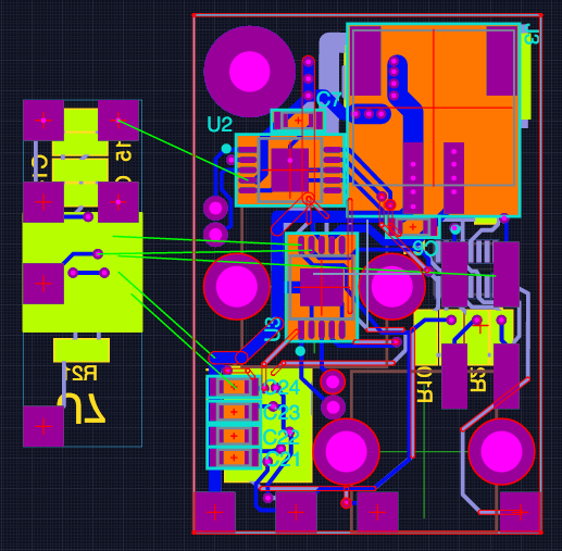
The completed design:You can check out the design here.
The smaller board will be mounted on the front at 90 degrees to the main board. The IR range sensor will mount on this to allow it to look forward.
The Required Fail:
I had hoped to have the design done by November 23rd as I was going on a holiday for a week the next day.
But I had made an error that I only discovered when I went to put the board in at OSHPark. I noticed I had no copper around the mounting holes for the motor mounts. I had made an error in creating the part.
Of course this meant I had to take more space for the mounts and re-work large parts of the design. If you go to the Upverter page I have marked the version where I realized the error. You can click on it and the hit the "play" button to see the changes from that version.
Simpler is better, to a point.
During the design I had to lose more subsystems. Especially after I fixed my part error. The number of IR distance sensors were dropped to one. I also removed the reset pin so I could switch to a 4 pin programming header. You don't need reset for SWD programming, just SWIO, SWCLK, Vin and GND. I will have to yank the power to reset, but there is just not enough space for a 6 pin header.
I was glad that I was able to retain the IMU. This means I will be able to use PID to steer based off the gyro. With a differential steering on a robot that is so asymmetrical it will be interesting to see how well PID handles it.
The compass on the IMU will probably be of little use as it is mounted directly under a motor. But on a design this small you are going to be next to a motor or coil for the buck/boost converter. So I had little hope for the compass from the beginning.
Next steps.
I have already sent the design to OSHPark to be manufactured. Next I will order any parts I don't have and wait for the boards to show up.
 HappyFox
Discussions
Become a Hackaday.io Member
Create an account to leave a comment. Already have an account? Log In.