 zakqwy
[update 12/8/2015, part 2: OSHpark cancelled the previous board and swapped the new ones in their place. Just got all the parts on order--the blue units were backordered so I found 'em via a different supplier. I ordered .. uh .. a lot of LEDs. More than I need for this project. Any ideas... ?]
[update 12/8/2015: I realized when I was updating the BOM that the resistor networks were sized for a 3.3vdc power supply. Unfortunately, due to voltage drop/current draw requirements, moving to direct USB power (5vdc) means I need larger resistor values for the InGaN units (four total). So I updated the schematic and PCB this morning and sent a panicked note off to OSHpark; with any luck I'll be able to squeeze the new design into their production queue. Either way, the GitHub repo is now correct.]
It got a bit tight around the ICs. We'll see how this shakes out. The USB connector pads are hilariously large compared to everything else. I hear OSHpark does slots now, but I opted to use 2.5mm holes for the structural bits.
No room for wavelength designations on the front, unfortunately...

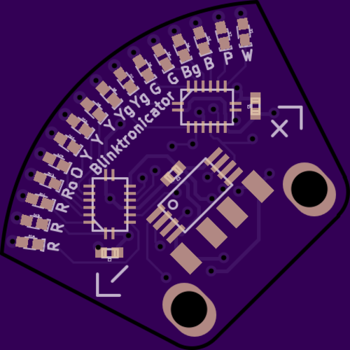

My apologies to all for dropping the ball with respect to symmetry--the two pulldowns on the back are embarrassingly unmatched. But at some point, you just have to call it good enough.
I think I still have a few things to do to comply with the contest (BOM, etc)--I'll also get the latest files into the github repo.
Discussions
Become a Hackaday.io Member
Create an account to leave a comment. Already have an account? Log In.
Oooh, first the arced LEDs, now a nice arced board. Pretty!
Are you sure? yes | no
I'm getting better at edge routing in KiCad, but my time would probably be much better spent importing graphics from traditional CAD program :-/
Are you sure? yes | no