Adam Curtis
-
Getting back to it
09/28/2016 at 00:38 • 2 commentsAfter a lot of traveling around I'm back in town and ready to work on the Electric Sonett some more.
I have all the parts I need to get some tests going and maybe take the car around the block.
look for more posts as I wire up the controller and batteries!
![]()
-
How I design
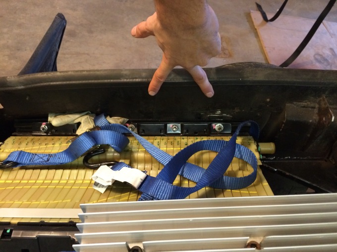
04/23/2016 at 23:22 • 0 commentsDesigning for this project required many different approaches. Sometimes it was easy enough to take measurements, design the part in question and make it according to those dimensions. Other times it would be exceedingly difficult to measure all aspects of a situation in order to obtain correct angles and placement. In these cases I often use a more fluid design and prototyping method. In the case of the battery mounts I decided that I would have the weight of the batteries resting on a couple reinforced spots on the battery pack and make several tabs that bolt to the car body as well. In this case I decided that the easiest way would be to make all of the hardware that I imagined needing and then spot weld everything in its correct place while the actual batteries were holding the space they would eventually occupy.
I like to use technology to help in this process. The Notes app on my phone can integrate pictures, text and drawings into a single document, which is easy to follow.
Here is an example of one way in which I prototype in the physical world.
Battery mounting hardware
![Image.jpeg]()
Two tabs with hole offset up
![C399190F-986F-4155-9B46-D4B3104469DE-1-2048x1536-oriented.png]()
(Having completed these tabs I give it a check mark while working in the shop)
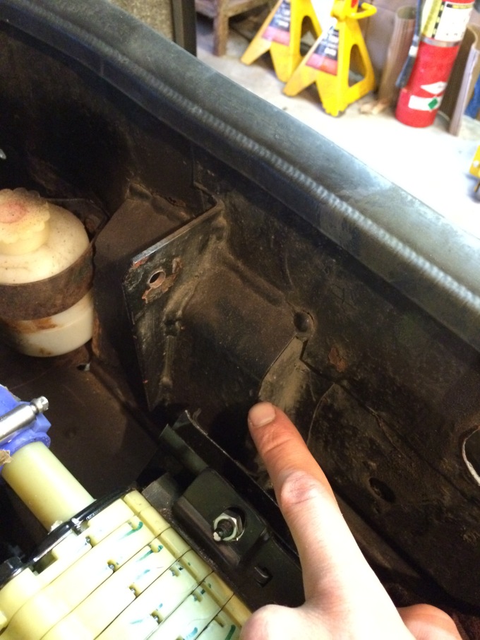
![Image.jpeg]() Mount to this surface. Triangle and tab
Mount to this surface. Triangle and tab![Image.jpeg]()
Make triangle mount
![Image.jpeg]()
Weld nut onto car, bolt through tab
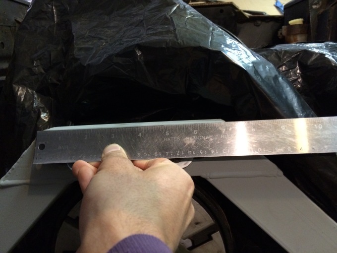
Make beefy steel pieces that mimic motor mount shape and bell housing shape to weld to sheet lining under battery sides. These sheet pieces welded to original tray. Maybe 20 gauge on the sheet with 12 or 14 gauge strip between two "pressure points"
The sheets need to be
11" x 20"
And 11" x 24"
Cut out 4 pieces of 12 or 14 Gauge measuring 4" x 4"
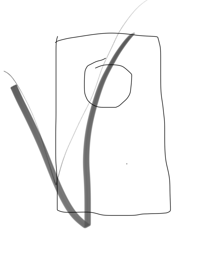
Motor piece
![IMG_2048.JPG]()
3/4 from top 1/2" slot
![IMG_2049.JPG]()
7.25" on top
With these notes I was able to fabricate all these little parts quickly and efficiently. I returned to the garage where the car is and rested everything where it would go. After making sure everything still fit right I started tack welding everything in place. I use compressed air to cool a weld quickly when it is close to combustible material. The batteries are insulated in a thick plastic housing so I was not worries about welding near them.
-
Trunk Floor Replacement
04/23/2016 at 23:21 • 0 commentsI just finished cleaning up the old rusty metal where the trunk used to be and tacking in the new trunk floor that I made the other day. Not to much to share. I will add a couple cross braces for support as my trunk has no structural bends stamped into it.
![IMG_2071]()
![IMG_2072]()
![IMG_2073]()
-
Throttle Pedal
04/23/2016 at 23:20 • 0 commentsOver the last couple days I've figured out where I want the throttle pedal. I'm using a toyota prius hall effect sensor pedal. So this pedal takes 5v from a power supply and then sends out a 0-5 volt signal to the controller depending on position. I'm going to set up a "hot pedal" regen brake system. This means the regenerative braking will kick in as soon as I start taking my foot off the "gas" pedal and even before I hit the brakes. I've heard that the Tesla model S has this setup and people like it a lot. I've heard people say that it is worse for your efficiency because you don't coast. Maybe, but the amount of energy used to spin the motor at the same speed as the drive wheels is probably only around 200 watts or less, which (although not a good thing) is pretty small compared with the 16,000 watt hour battery pack. I will monitor the motor as I start testing the car and if it seems that the free-spin draw is excessively high, I will switch over to the standard regenerative braking activated by the brake pedal. This will allow me to coast without any draw on the battery pack.
![IMG_2044.jpg]()
To set up the throttle pedal, first I made an aluminum mount in the approximate shape that I would need. I cut it across the front so I could bend it at the bend in the firewall of the car. I bolted the aluminum where I wanted the pedal. Then I duct taped the pedal to the aluminum mount and tested using it. It turned out that it was too close to the brake pedal and I kept bumping it when "emergency" stepping on the brake.
![IMG_2045.jpg]()
Next I modified the aluminum mount so that I could move the pedal over to the right slightly. I TIG welded the aluminum at the angle that I wanted it and bolted the pedal to it.
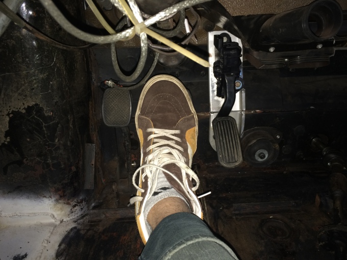
![IMG_2079.JPG]()
In this final position I was no longer bumping the throttle while hitting the brake and the throttle was comfortable on my foot at all angles.
![IMG_2082.JPG]()
Voila! I still have to hook up the wiring and run it to the controller, but the mount is solid and I like how it feels.
-
Fitting it in the Engine Bay.
04/19/2016 at 01:54 • 0 commentsBecause of weight distribution problems and lack of storage space I decided to try and fit two of my three battery modules in the engine bay instead of the trunk (The smaller two modules.. 30s3p and 18s3p modules) This was immediately impossible because of my motor mount. I modified the mount so it would take up less space and now I'm back at trying to get everything into the engine bay. I successfully bolted the batteries to the modified (cut up) battery tray (the huge T shaped ones that the chevy volt is famous for). I cut that up into three parts so my three modules will all be bolted separately.
I think I've figured out how the batteries will fit in the engine bay. Now I'm concerned about air-flow around the heat sink on my controller. This is an old Kelly controller (apparently they are infamous for over-heating issues). I'm not worried about the batteries over-heating because I will have them wired 24s 12p which means that each cell is supplying less than 8.33% of the maximum 500 amps the controller is rated at. Doing the math shows that each cell will be asked for no more than 41.67 amps at peak draw. For some reference the 2011 Chevy volt is rated at 149 horse power, which is equivalent to 111.1kW. The Chevy volt battery pack is rated at 360 nominal volts and actually operates between 300 and 400 volts depending on the state of charge and engine load. Let's do the math with 360 volts because that's nominal voltage.
power (watts) = volts * amps. So 111.1kW=111,100 W = 360 V * amps
That gives us about 310 amps peak draw on a 96s3p battery pack so each cell can provide just over 100 amps with proper cooling. I don't have proper cooling yet, but I plan to. But as long as I keep the load on the batteries to half of the original I'm probably fine. Right? Any smart people who know better, please tell me before I blow up.
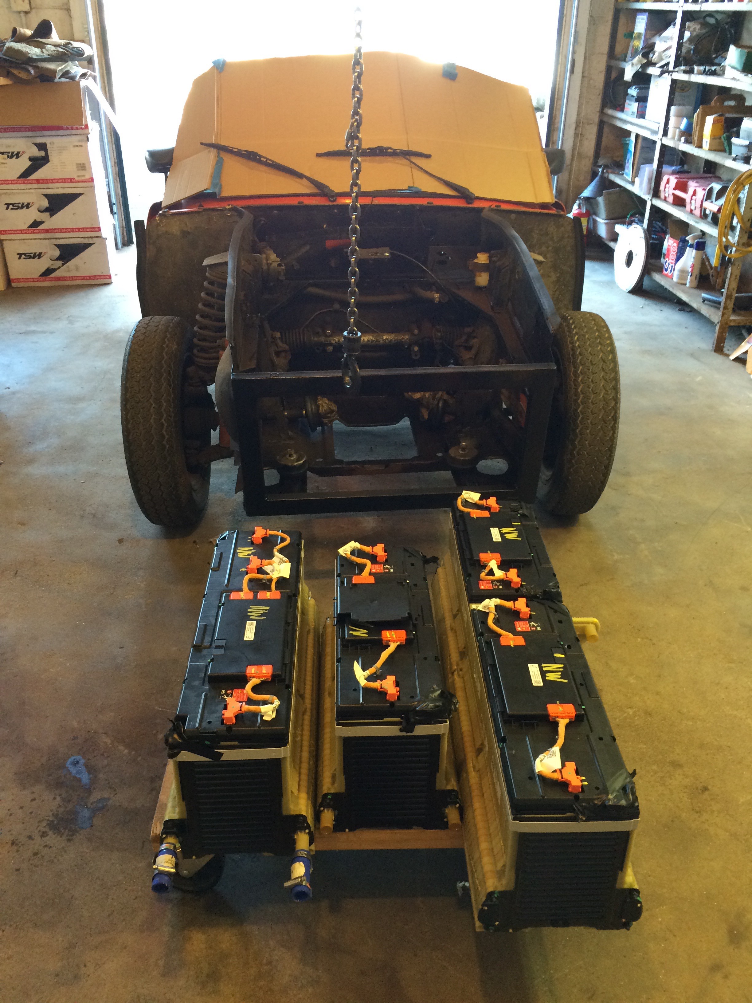
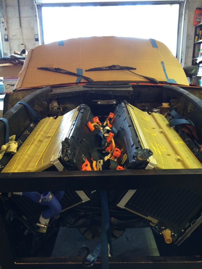
![IMG_2033.jpg]() Here's the batteries resting in the engine bay above the motor and transmission. See any problems? I'll make a metal battery mount that bolts into the engine bay and tranny/engine mounts.
Here's the batteries resting in the engine bay above the motor and transmission. See any problems? I'll make a metal battery mount that bolts into the engine bay and tranny/engine mounts. ![IMG_2038]()
I can fit the bonnet over the batteries but there is not quite enough room for the heat sink on top of the controller. The controller will either melt or self-limit without a heat sink. What if I put the heat sink through the hood? Is that blasphemy?
![IMG_2039]()
Should I cut a hole in the hood for the heat sink or just leave the hood off until I figure out a liquid cooling option?
![IMG_2041]()
What do you think about the aesthetics of this? Maybe I could get a scoop...
-
Front Axles
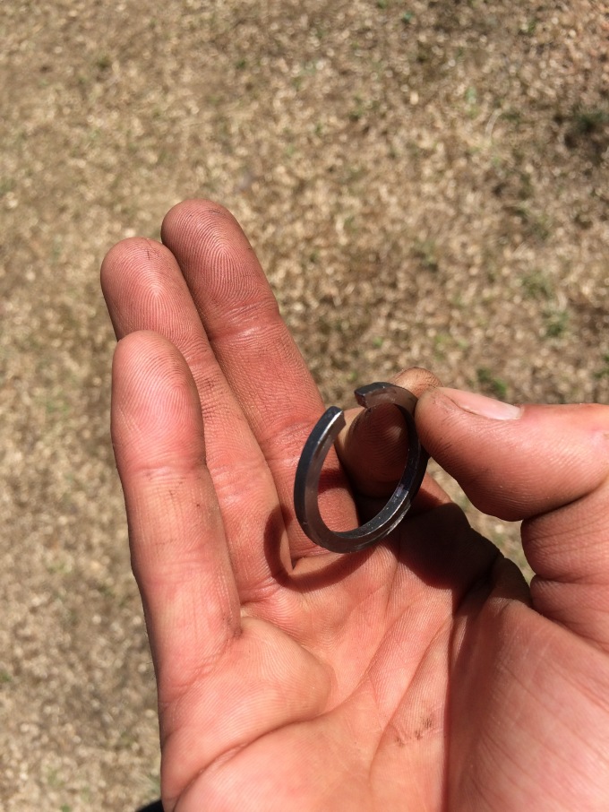
04/19/2016 at 01:15 • 0 commentsI pulled the front axles out to put new rubber boots over the CV joints in the front wheels. YOU DON'T NEED TO DO THIS. THE RUBBER BOOTS FIT OVER THE T-DRIVERS! Anyway, I learned that after I had already broken a circlip (C-clip) in this case the stop-ring that keeps the axels from going too far into the CV joint. I talked to my friend Patrick who let me look through his Sonett parts bins but no luck. I talked to Chris and he had a couple, plus an extra lock ring (a thinner ring that keeps the axle in). I drove out to Worcester and picked them up. Getting the axles back in was harder than getting them out (which was as easy as hooking a ratchet strap to the T-drivers and pulling the axle straight out of the wheel hub). I broke one lock ring and had to use the extra. Getting the axles back in is easy if you do one thing. MAKE SURE THE LOCK RING IS BENT TO THE SMALLEST CIRCLE IT CAN BE AND STILL GET IT ONTO THE AXLE. Once I figured this out it was as easy as hammering the axles back into the CV joints. Before I figured that out I was trying to get the lock ring pushed into the CV joint while the diameter of the lock ring was greater than the diameter of the splines on the axle. This meant that the CV joint was pushing part of the lock ring over the outside of the spline instead of into the grove where it is supposed to live. I greased everything first and my dad cleaned and greased the needle bearings in the T-drivers (every one) (Thanks again to Chris for extra needle bearings, I was one short somehow...)
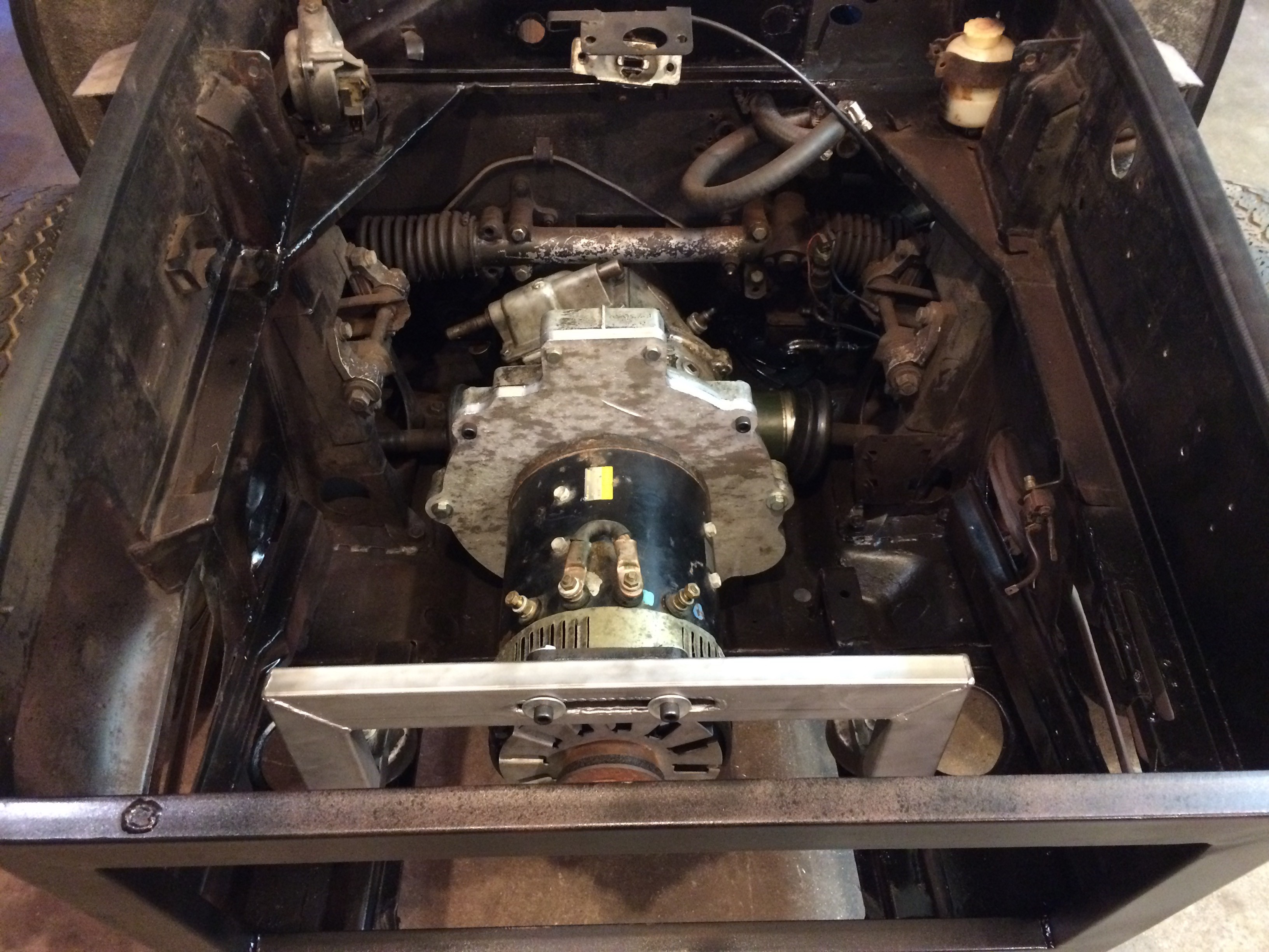
I now have it all back together and dropped the motor/transmission in. I even hooked up a 12v power supply to the motor and let that drive the car forward.
The drive train is all set up and working!
![IMG_1973.jpg]()
This is the stop-ring. The lock ring is made of a wire. A tip for getting these lock rings on is use a small round file in the gap to make gripping it with a spreader easier. My spreaders have round pins for teeth and the flat ends of this clip didn't work well.
-
Revisiting the Smart motor
04/14/2016 at 14:03 • 0 commentsSo as you know from thoroughly reading each one of my blog posts to date... Just kidding, no one does that. I'll just tell you.
I've TEMPORARILY set aside my smart car motor and controller until the software hack is complete. In the meantime I am using a forklift motor and an old Kelly controller. This is a simpler system and much less amazing in lots of ways but the motor spins, which is good.
There's the background. Here's the update.
I'm working with a friend of mine at Worcester Polytechnic Institute to get a custom transmission input shaft made with a spline for the smart car motor. He and I drew it up in SolidWorks based on measurements that I'd taken from the Sonett transmission input shaft and the female splines on the smart car motor.
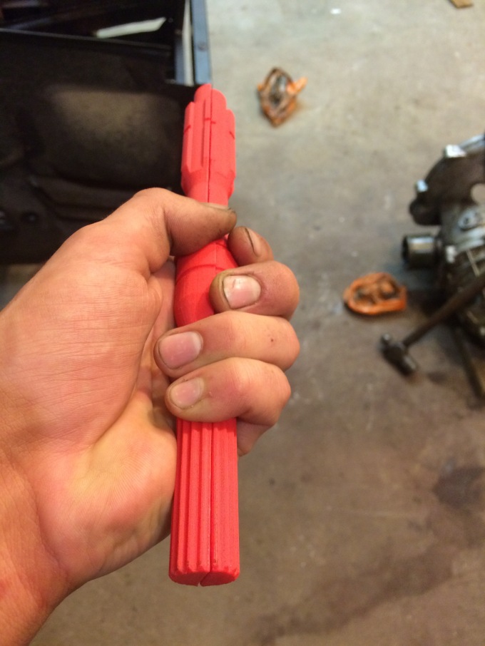
Just the other day he 3d printed the first prototype to check dimensions. It fits! He is going to machine the next prototype and then we're going with chromoly or something equally awesome.
![IMG_1971.jpg]()
Here is the shaft in the smart car motor. In order to 3D print it he had to make it in four pieces but it seems to be fitting great!
![IMG_1972.jpg]()
-
Machining the input shaft
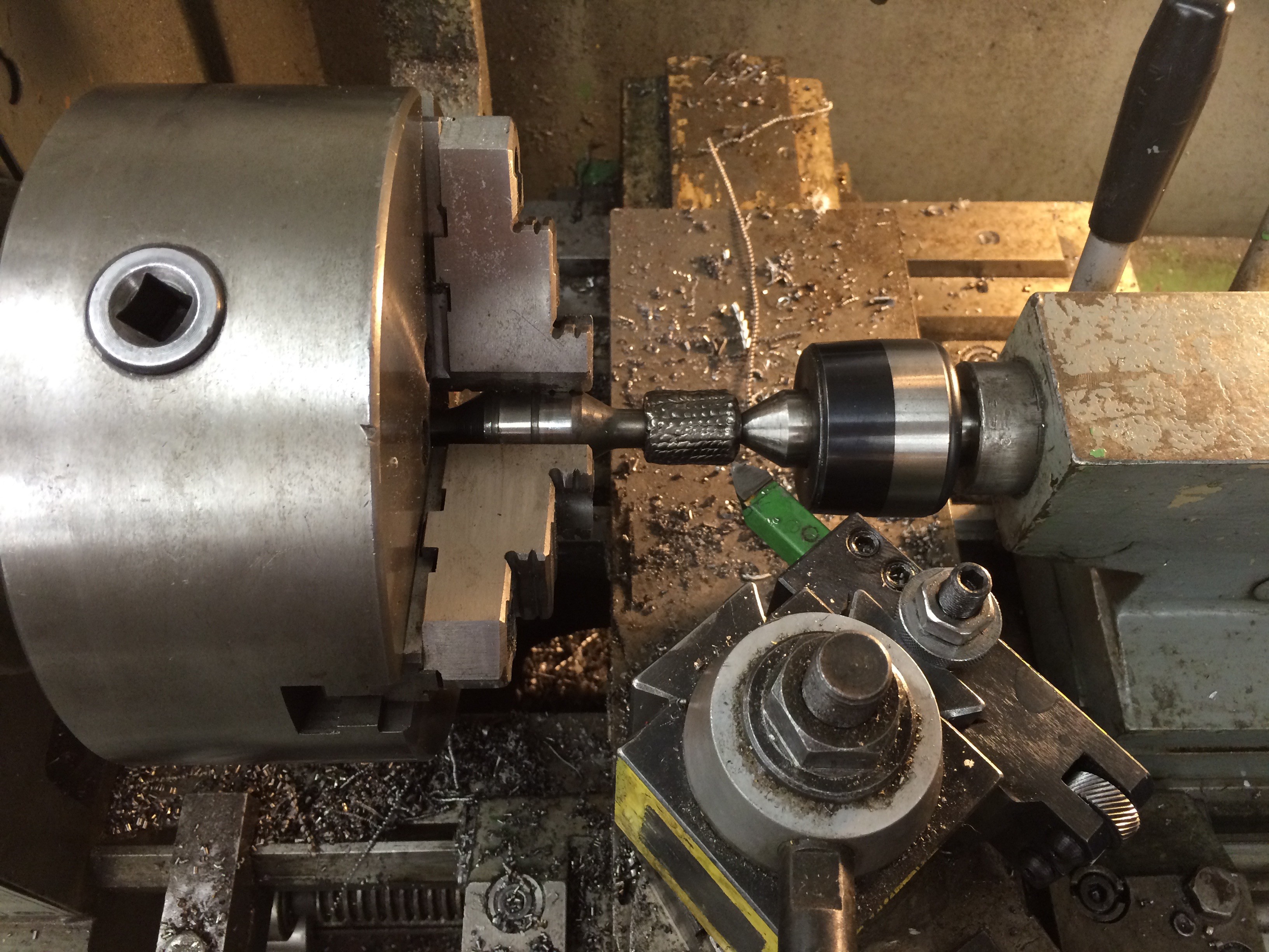
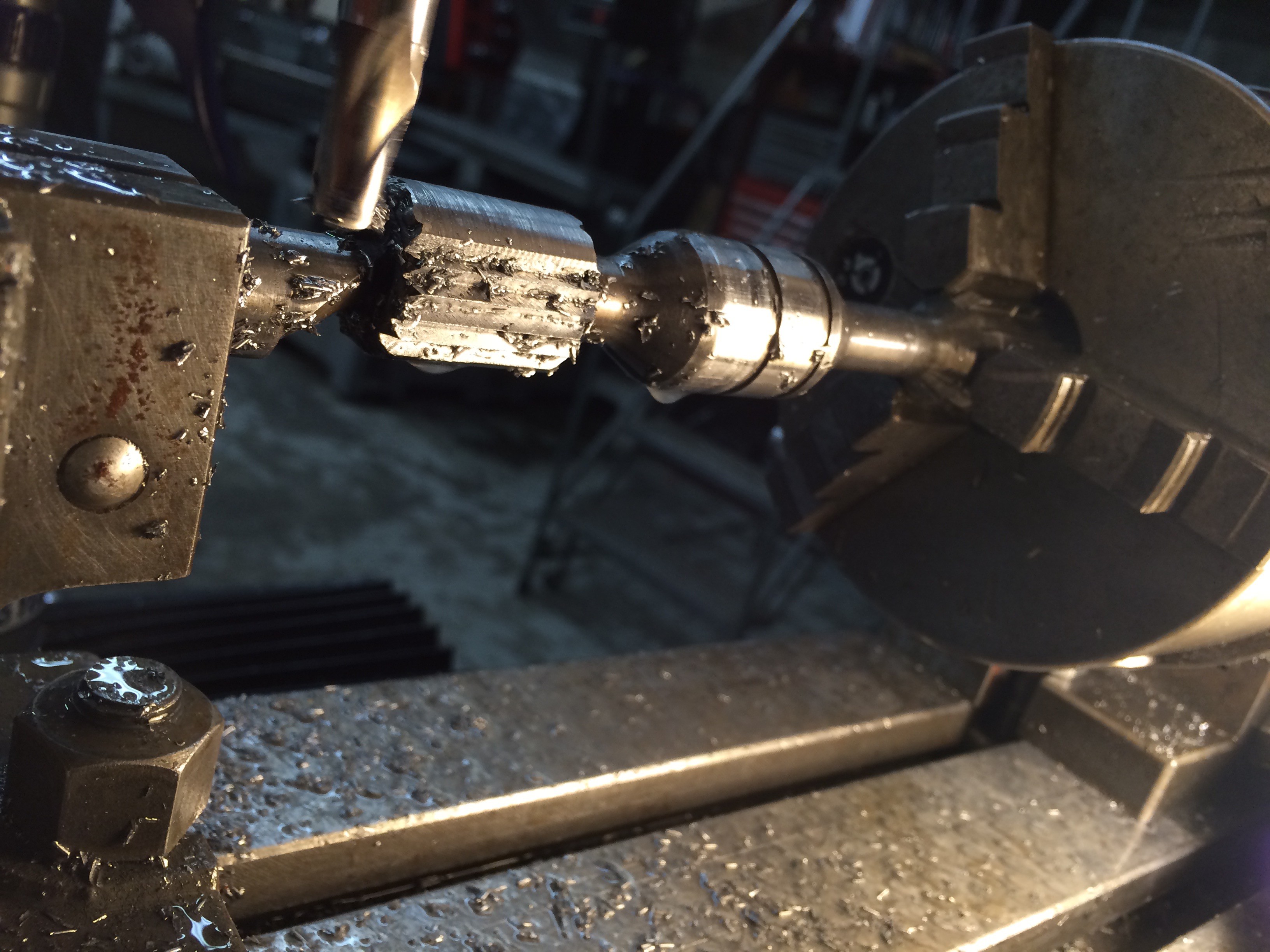
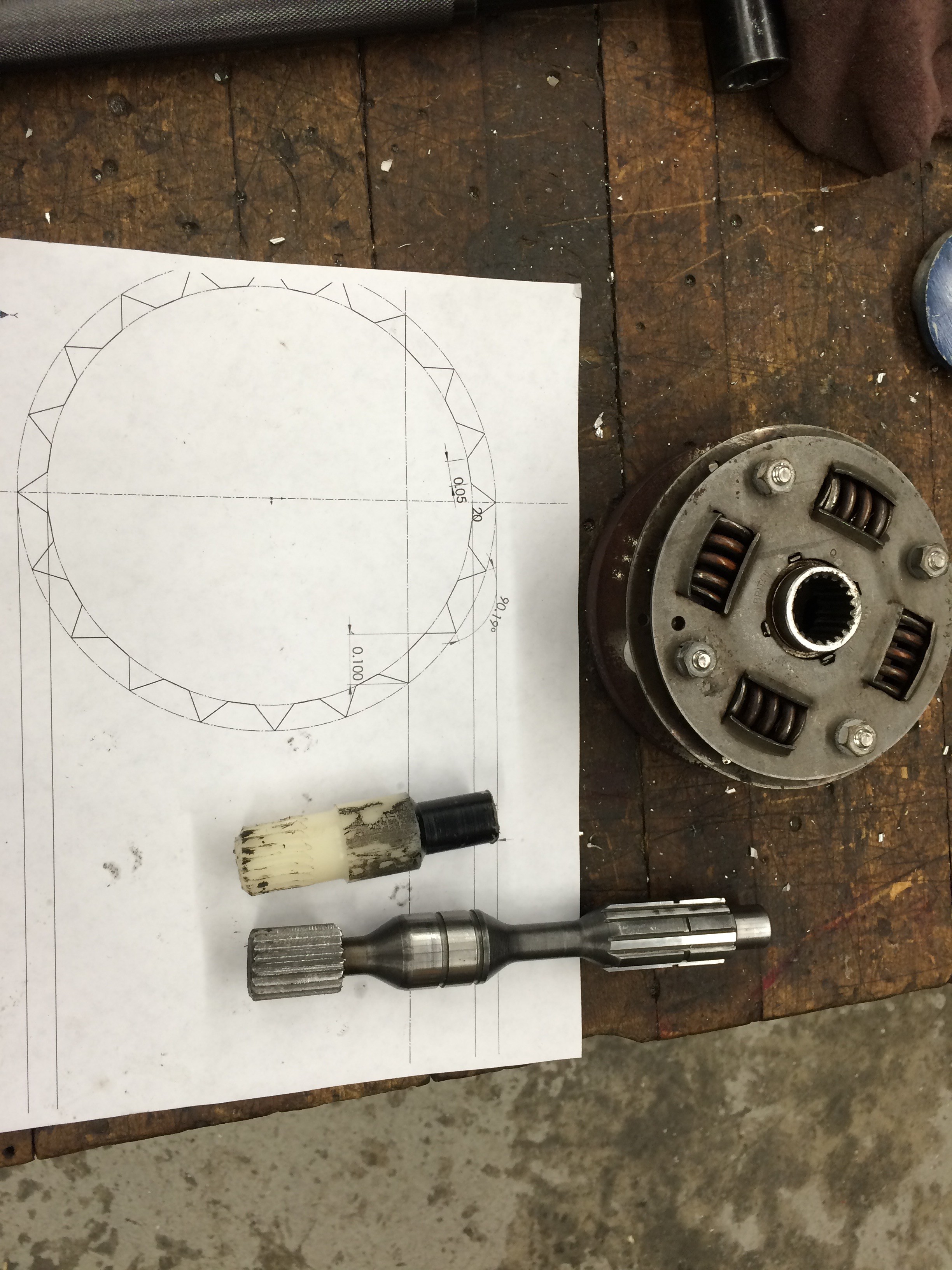
04/13/2016 at 04:17 • 0 commentsAlong with working on my battery pack I machined the splines onto my transmission input shaft today.
I'm not 100% sure this will hold up to abuses but it will get me going until I can afford to have a rod of chromoly CNCed into a permanent solution.
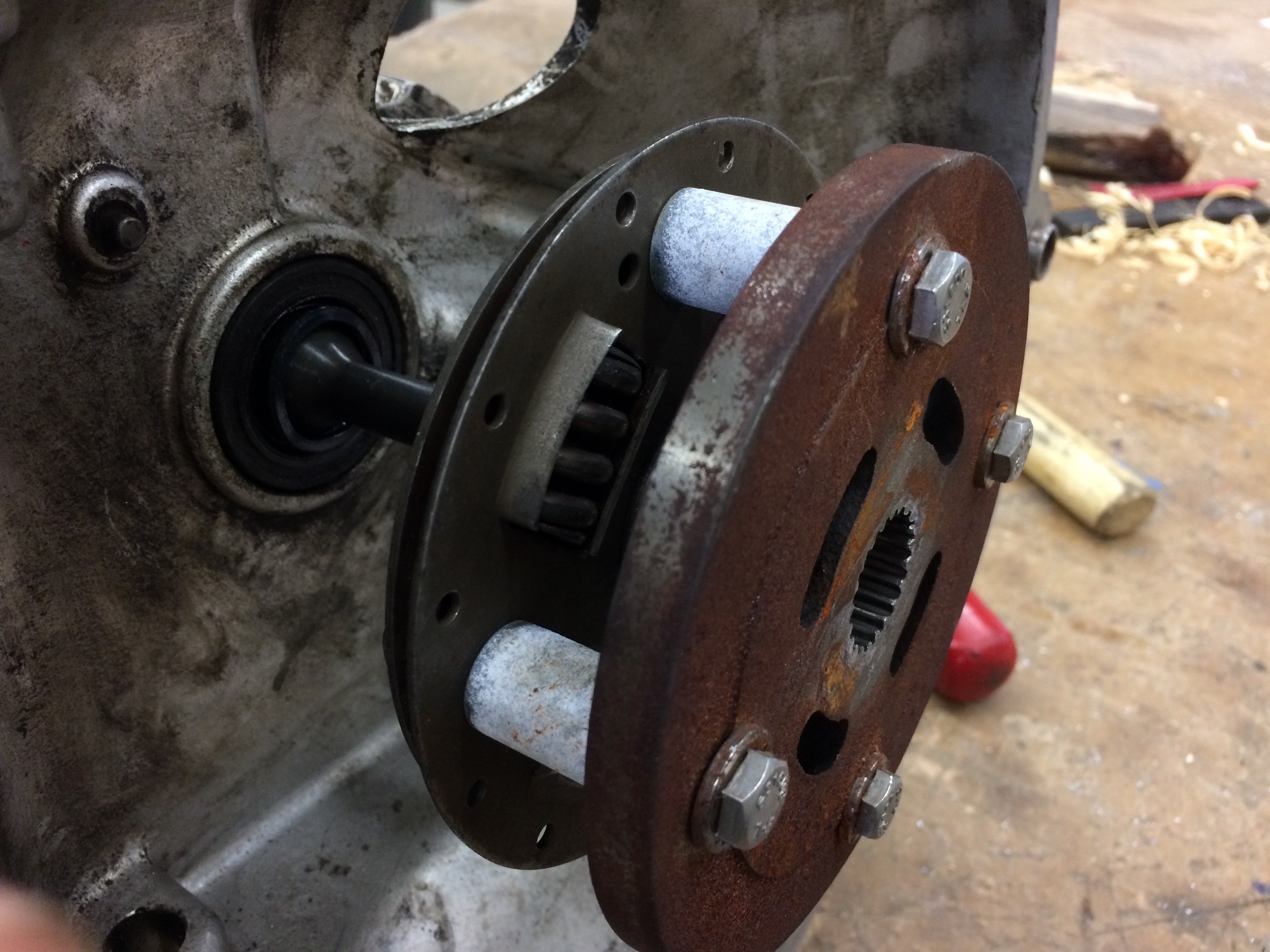
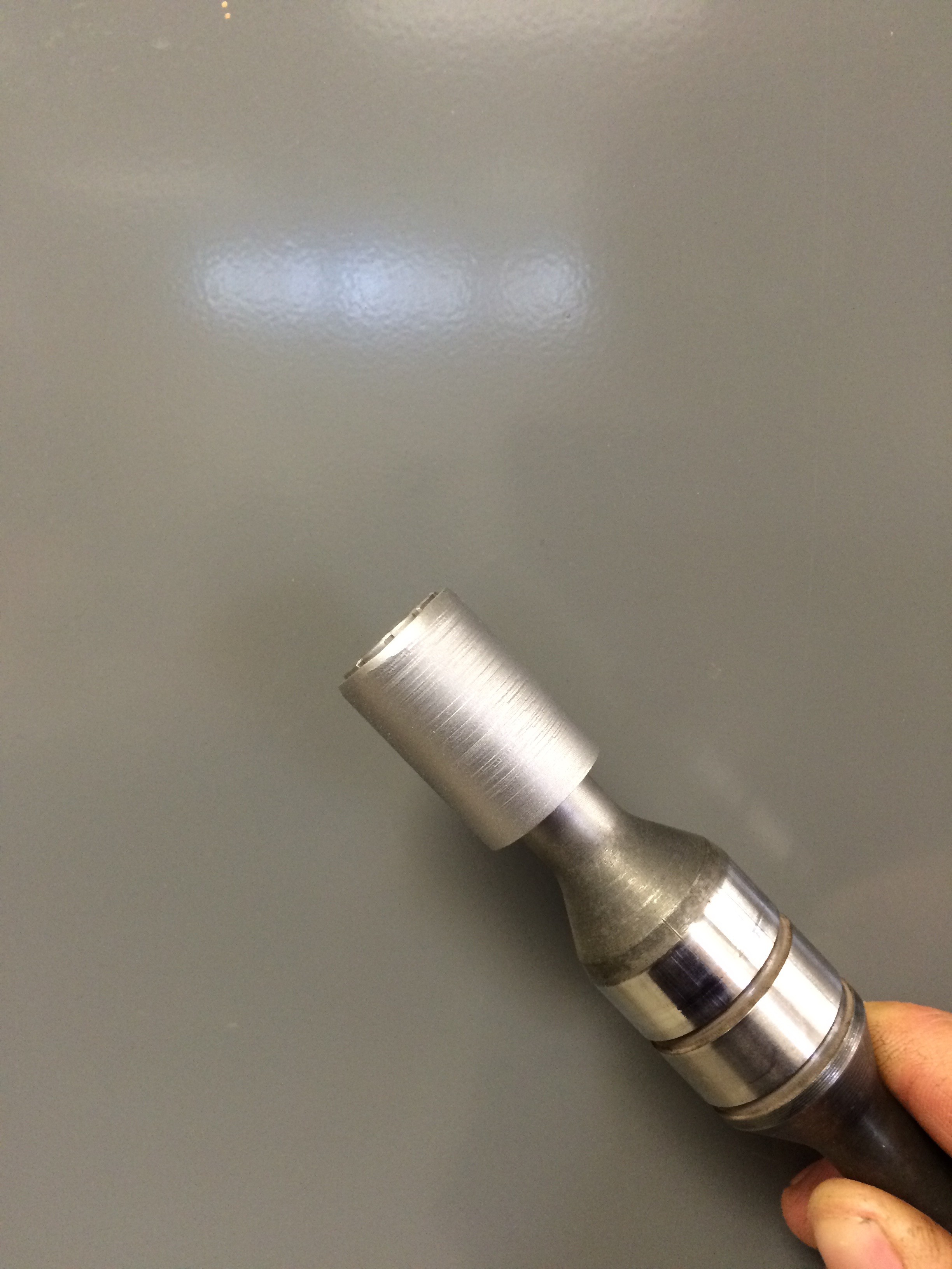
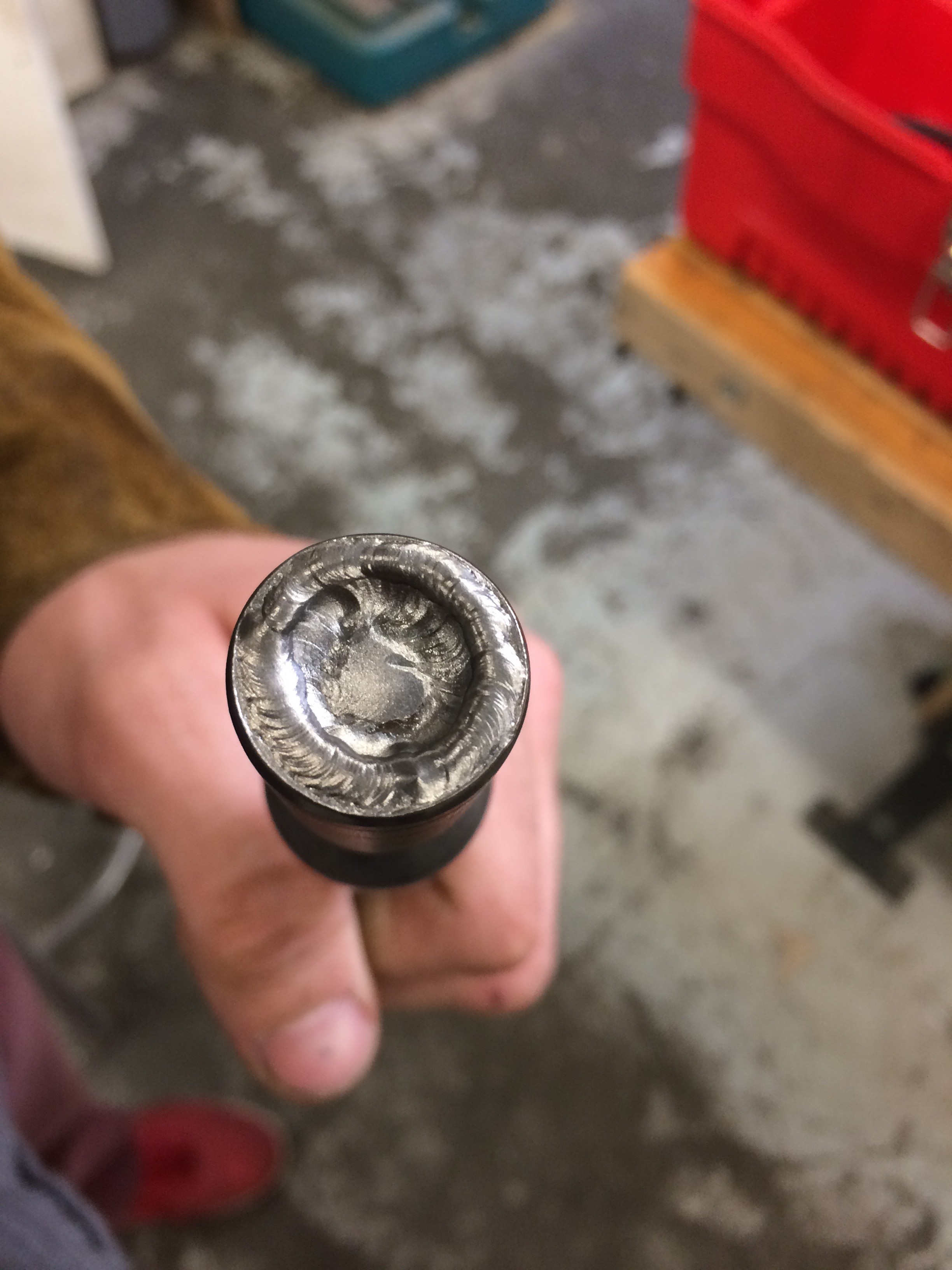
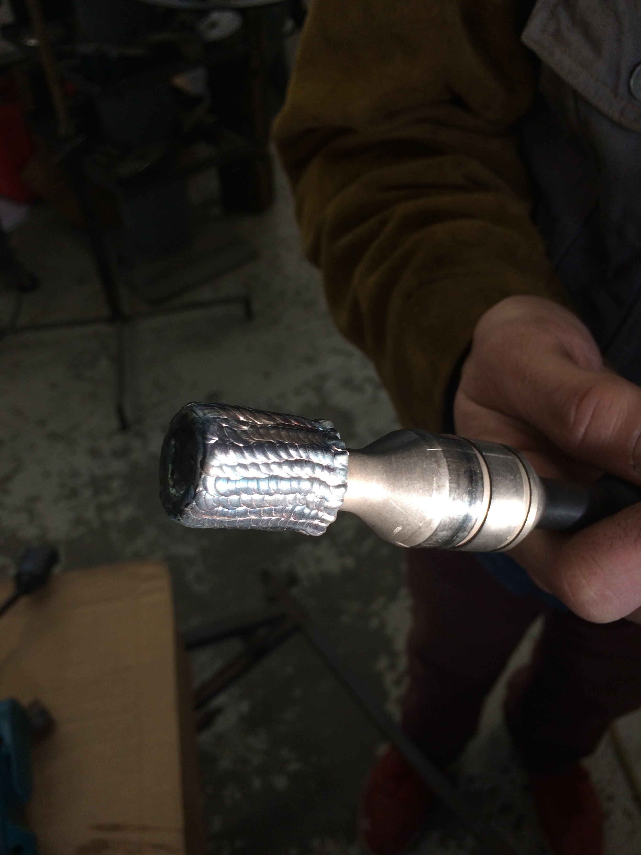
After drawing up the splines that I needed to make to fit my adapter coupling I found that the angle between splines was a perfect 90 so I just used a flat end mill and cut with the corner at just the right height and depth while my shaft was in the indexing head on the Bridgeport table. There were conveniently 20 splines and the indexing head is a 40 to 1 ration so I'd cut a spline, swing the arm twice and repeat.
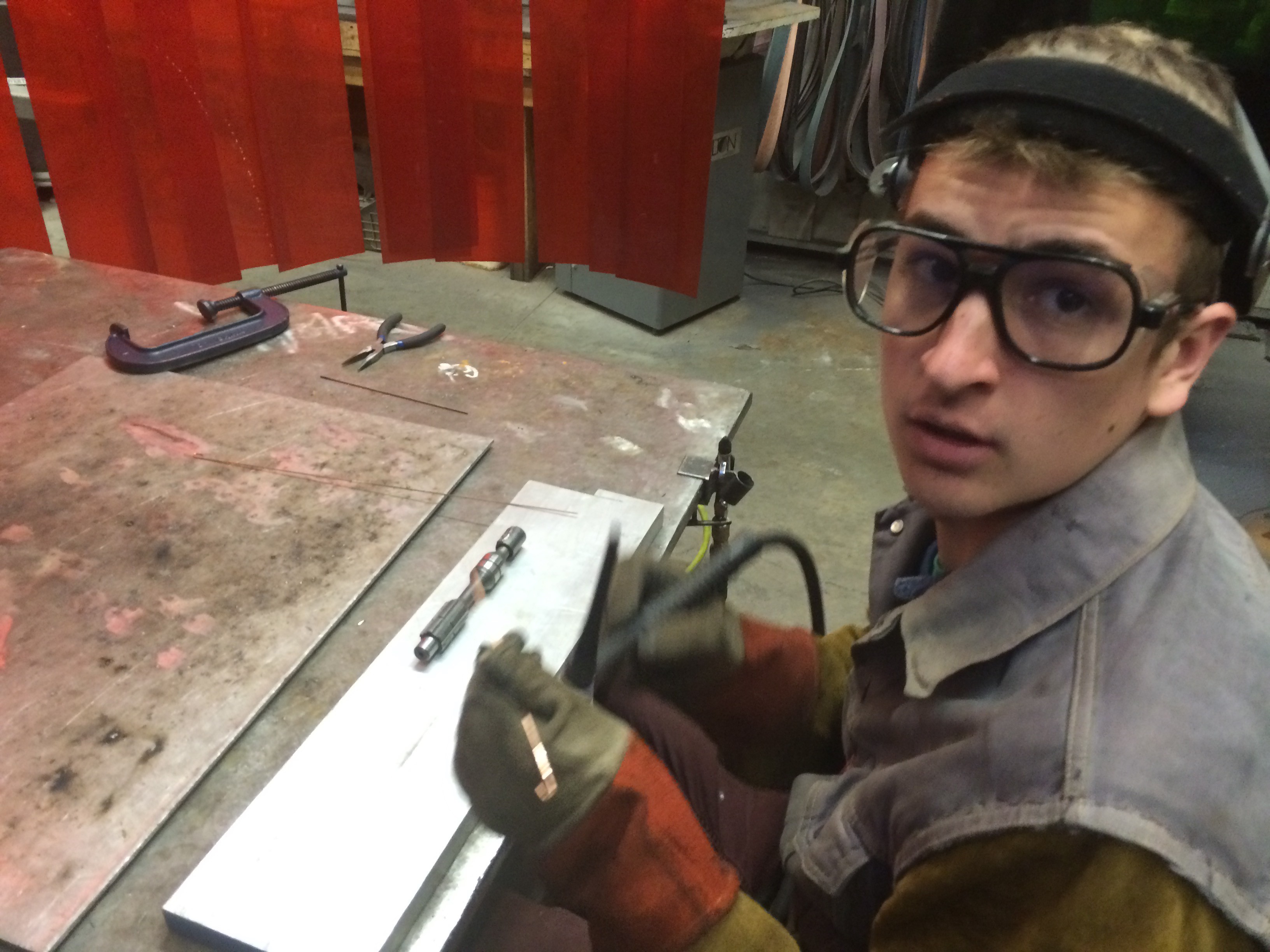
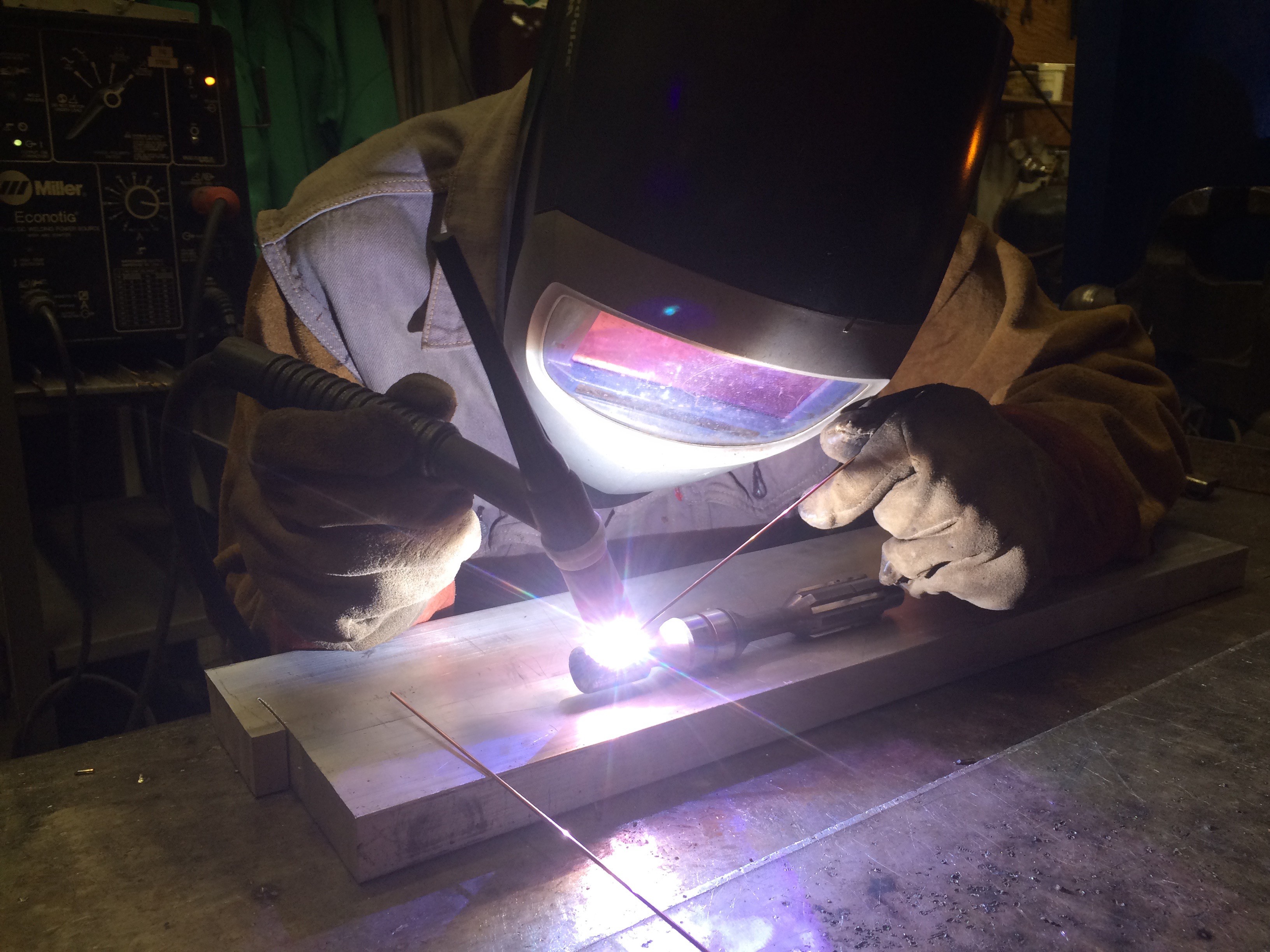
I cut these splines into metal that my friend and welder protoge Rhett Courser laid onto the shaft with his magical TIG skills.
Here are pictures so you can understand what I'm talking about.
![]()
![]()
![]()
![]()
![]()
![]()
![]()
![]()
-
Chevy Volt battery pack tear down
04/13/2016 at 03:58 • 0 comments4/12/16
Today I got a battery pack out of a 2011 Chevy Volt with 50,000 miles on it. Let's hope their pack lives up to their 100,000 mile guarantee. It should as the car software is designed never to use the bottom end of the pack's capacity, which keeps it in a very stable voltage range.
I'm going to take the pack apart and rewire the cells into a 148 volt configuration, which I will charge with the PFC-2500 from Elcon. This is a 2.5kW charger so the charge times are going to be abysmal but it's all I can afford right now.
{{EDIT* 4/14/16
Last night I opened up each sub-pack to discover that the cells are spot welded together in sub-sub-packs of 3p12s and 3p6s. There are seven packs of 3p12s and two packs of 3p6s. I can't unweld them so I need to work with a voltage that can be accommodated by these packs. Also, I want to use all of the cells so they age at the same rate and I can reconfigure them later into a 360 volt pack once more. That means my only two options are 90volts or 180volts. I'm using (temporarily) an old Kelly controller that can't handle any more than 178 PEAK voltage so I have to run the 90 volt system until I can go back to the Smart car controller. This will be a slow car. }}
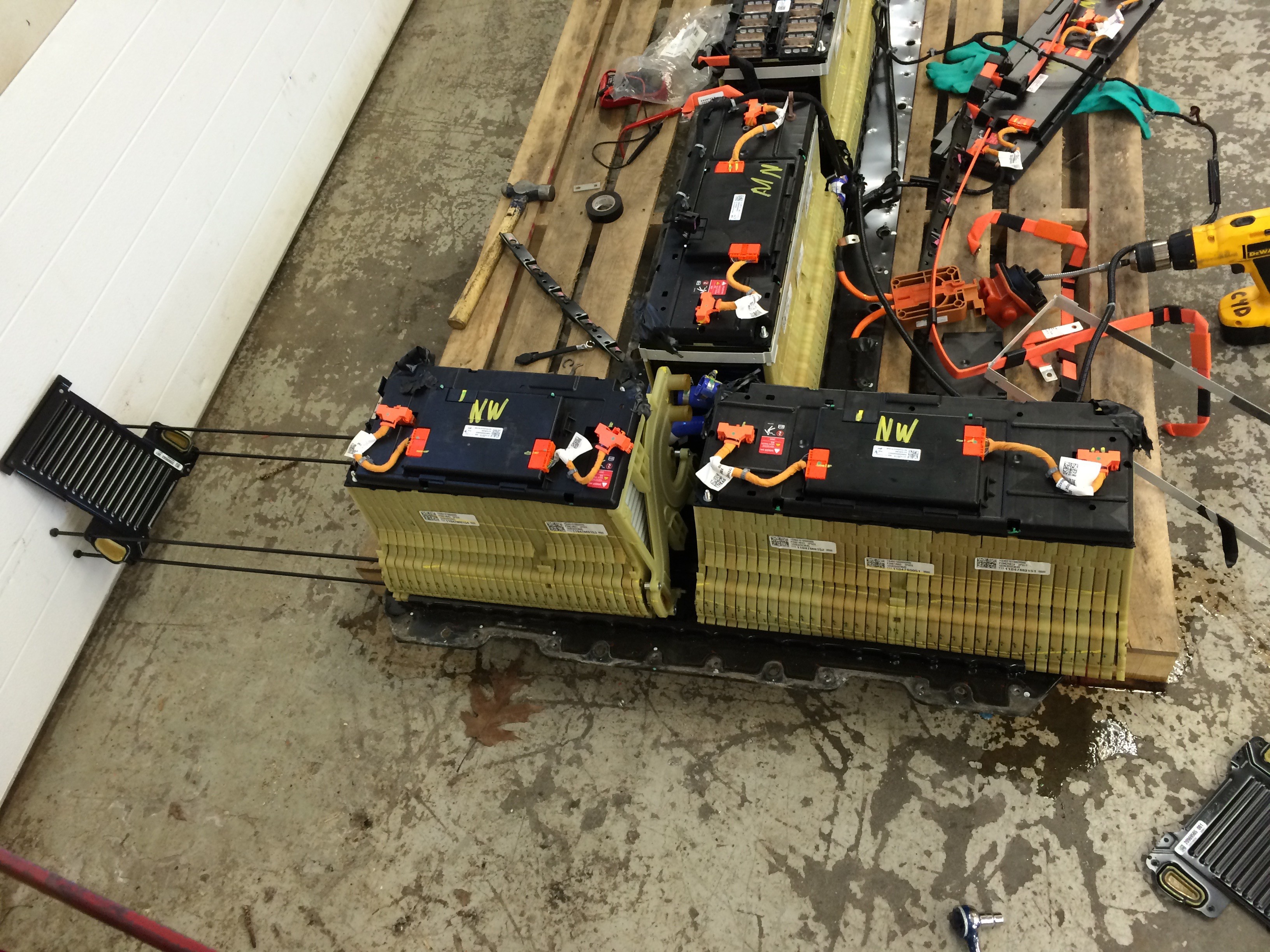
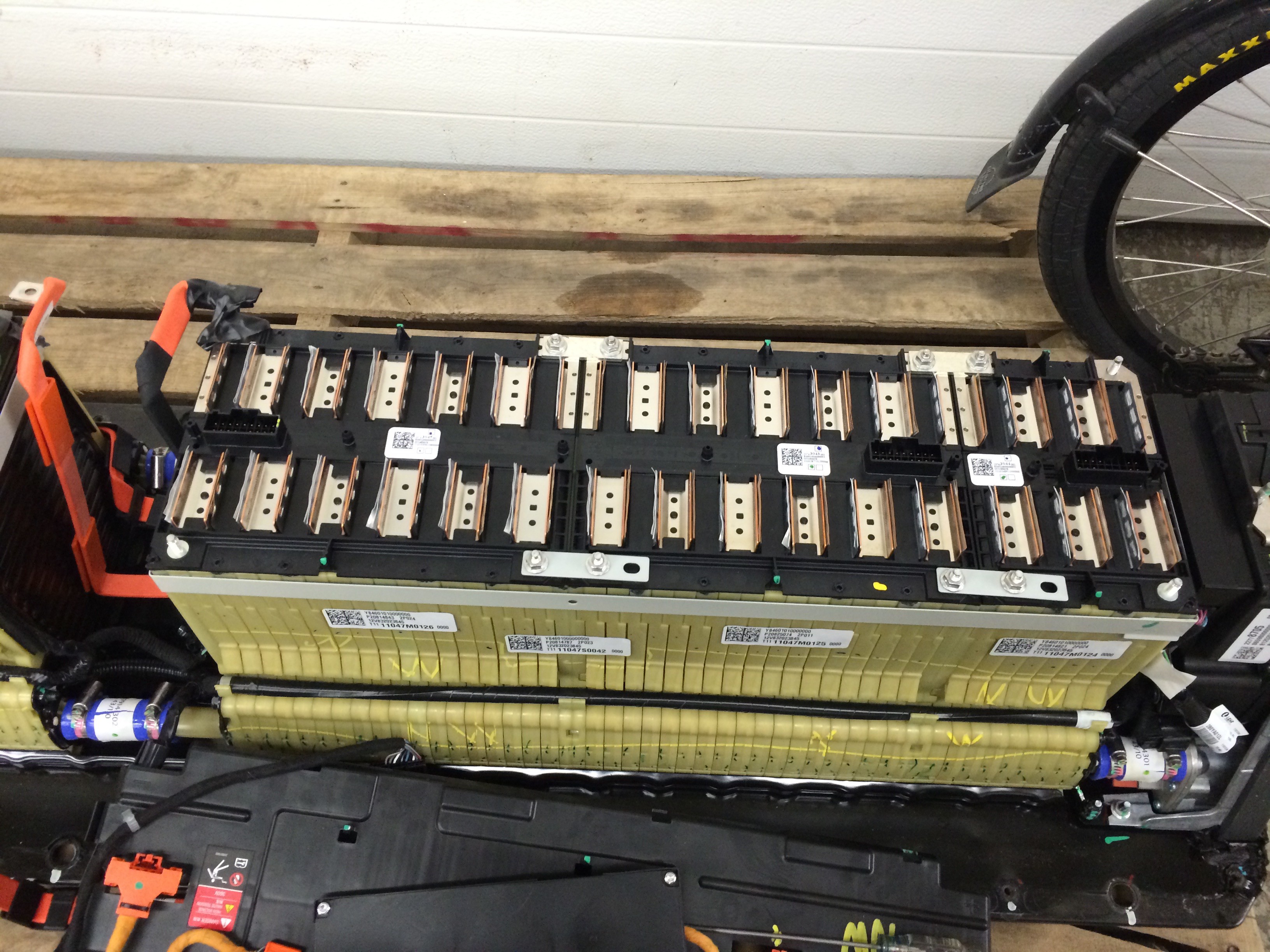
Here are some pictures of the inside of a Chevy Volt battery pack from 2011.
![]()
I took all the buss bars off to disconnect the four sub-packs before I went deeper.
The orange cables/plugs that go into the top of the batteries have cell level connectivity. So it should be pretty easy to put my own BMS on these batteries using those plugs!
![]()
I'll post more pictures soon of what is under these plastic covers. The battery cells are welded together. That's going to pose problems when I try to take them apart to rewire them.
{{EDIT 4/14/16
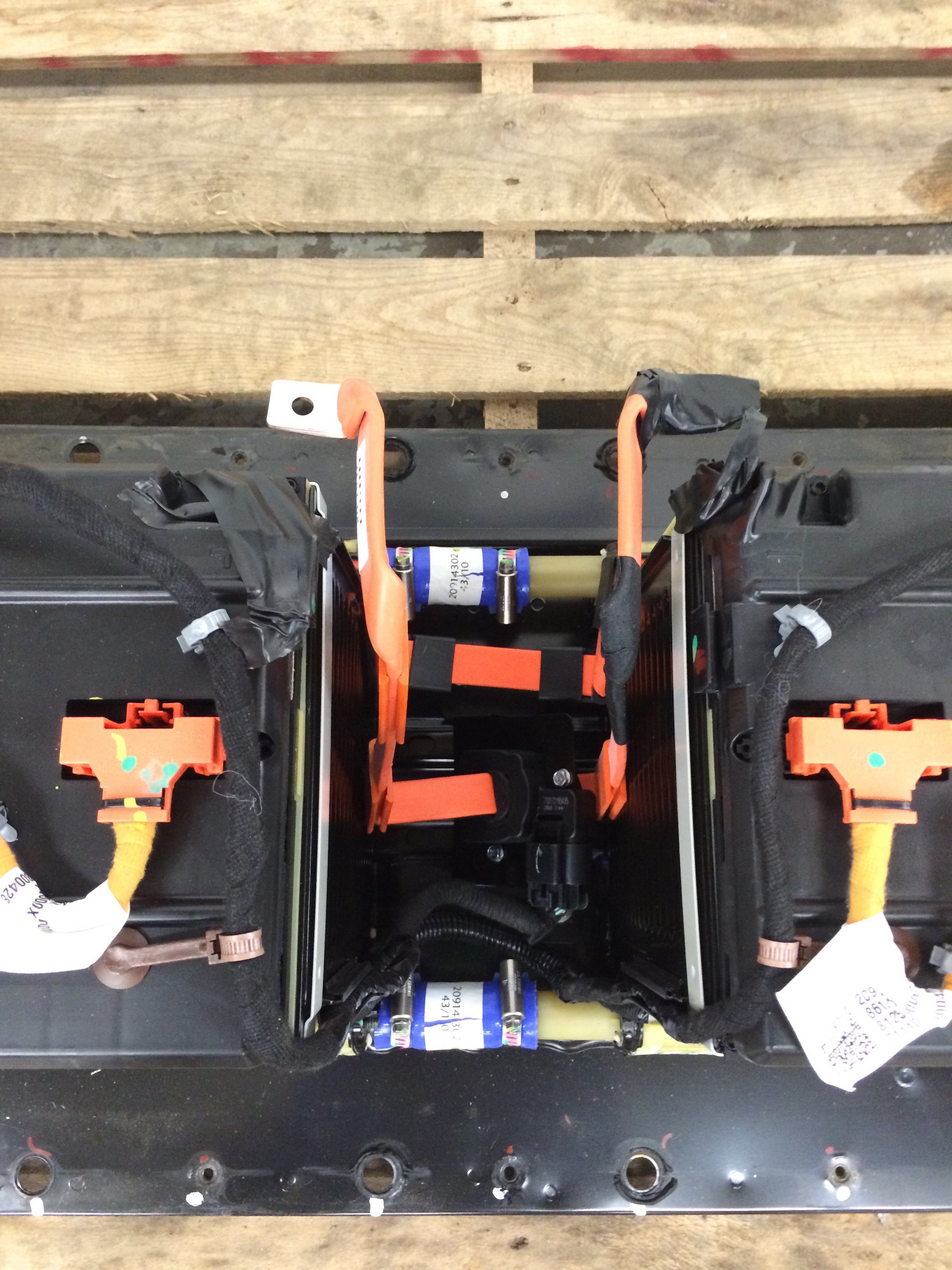
Sure enough. There's no way I'm getting those cells apart. Check out these pictures and descriptions of the Chevy Volt battery pack...
![]()
Here are the cells. Above are two sub-sub-packs of 36 cells (3p12s) and an 18 cell on the right (3p6s) You can see where they're connected with bus bars.
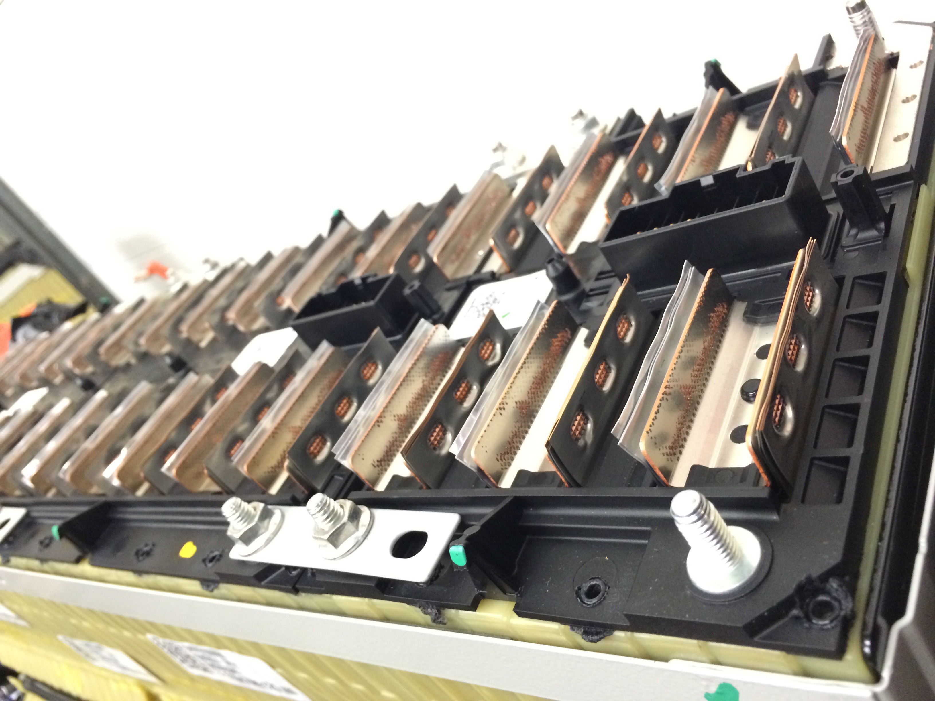
![]()
Check out these sweet spot welds... damn.
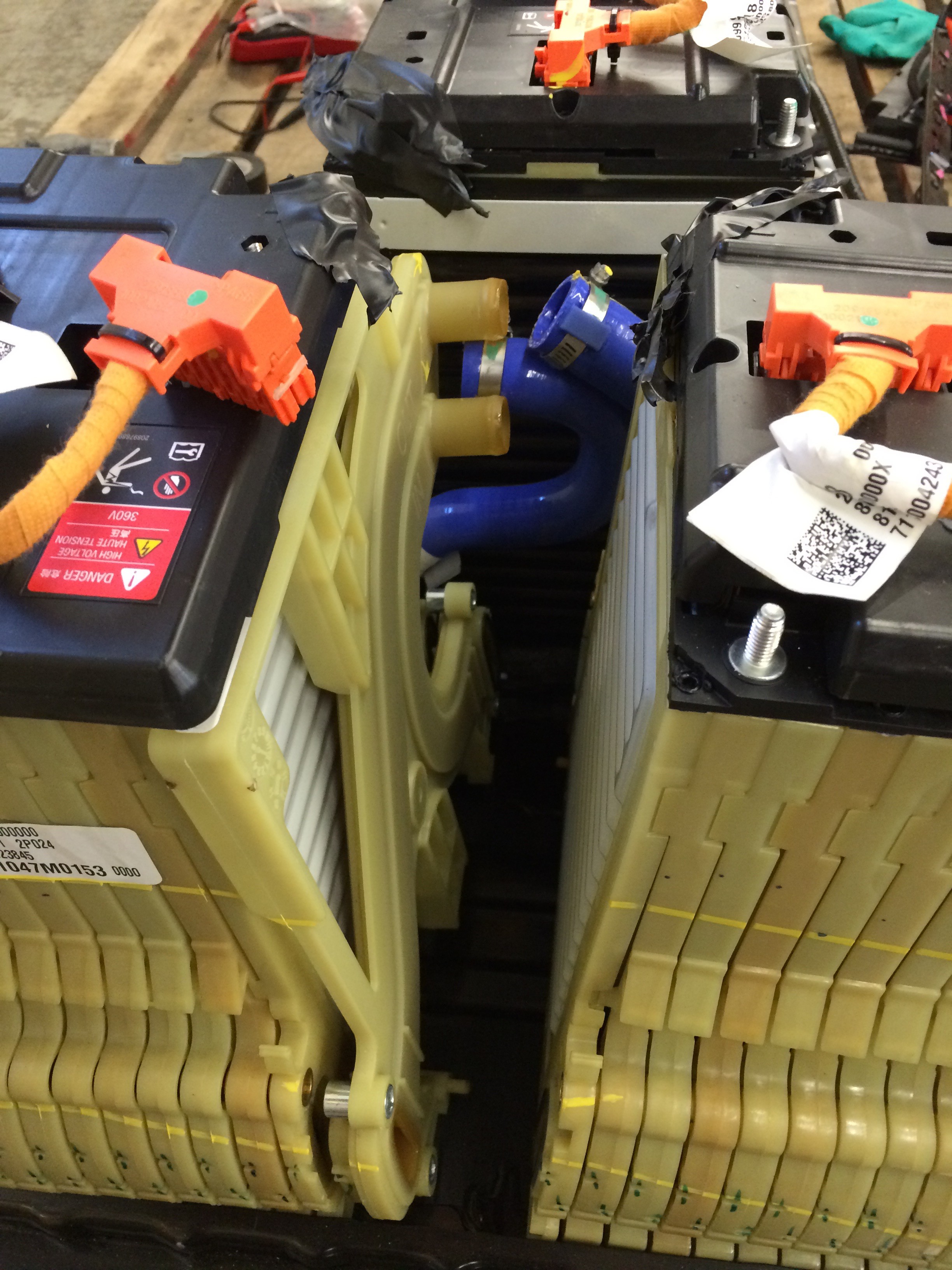
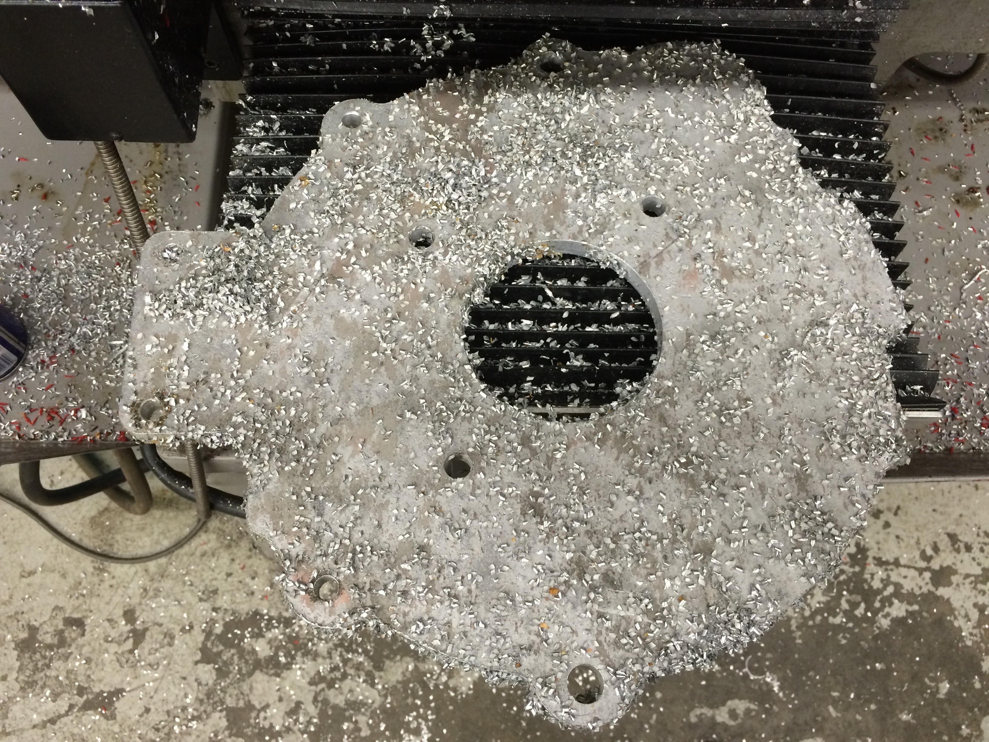
![]() These huge bricks are held together with glue, steel bands and 3 foot screws. I wanted to see what the cooling system was like so I started taking this apart down to cell level. As soon as I loosed the 4 bolts that hold the black endplates together coolant started leaking out from every cell. Here's what the 4 bolts look like.
These huge bricks are held together with glue, steel bands and 3 foot screws. I wanted to see what the cooling system was like so I started taking this apart down to cell level. As soon as I loosed the 4 bolts that hold the black endplates together coolant started leaking out from every cell. Here's what the 4 bolts look like. ![]()
Here you can see the four bolts coming off to the left and you can see that all of the cells in the module are spreading apart and spilling coolant on the floor. More detail below.
![]()
Each cell has little o ring gaskets to seal the coolant inside.
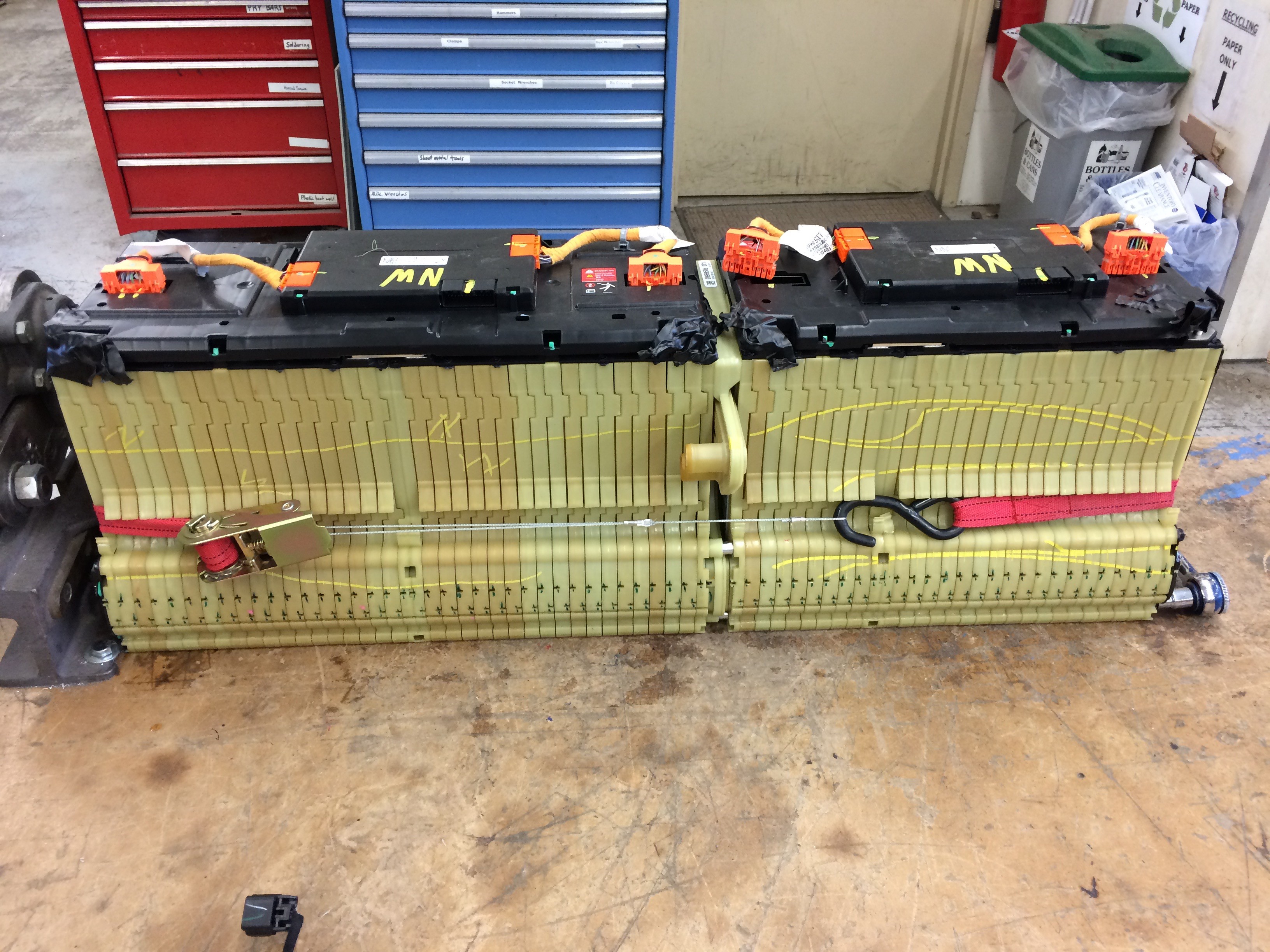
After letting the cells separate I had to use a ratchet strap to pull the module back together before I could get the bolts back in.![]()
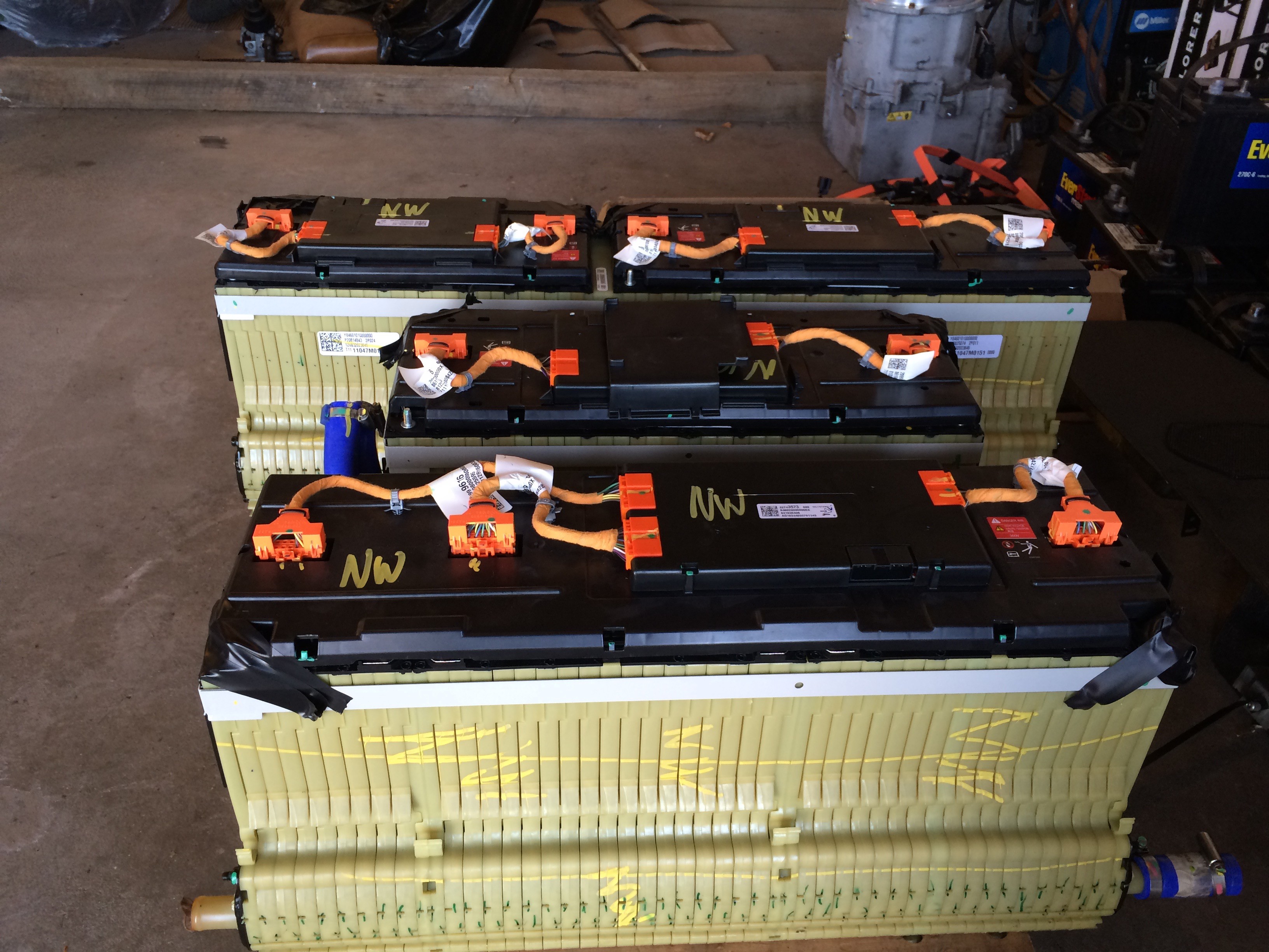
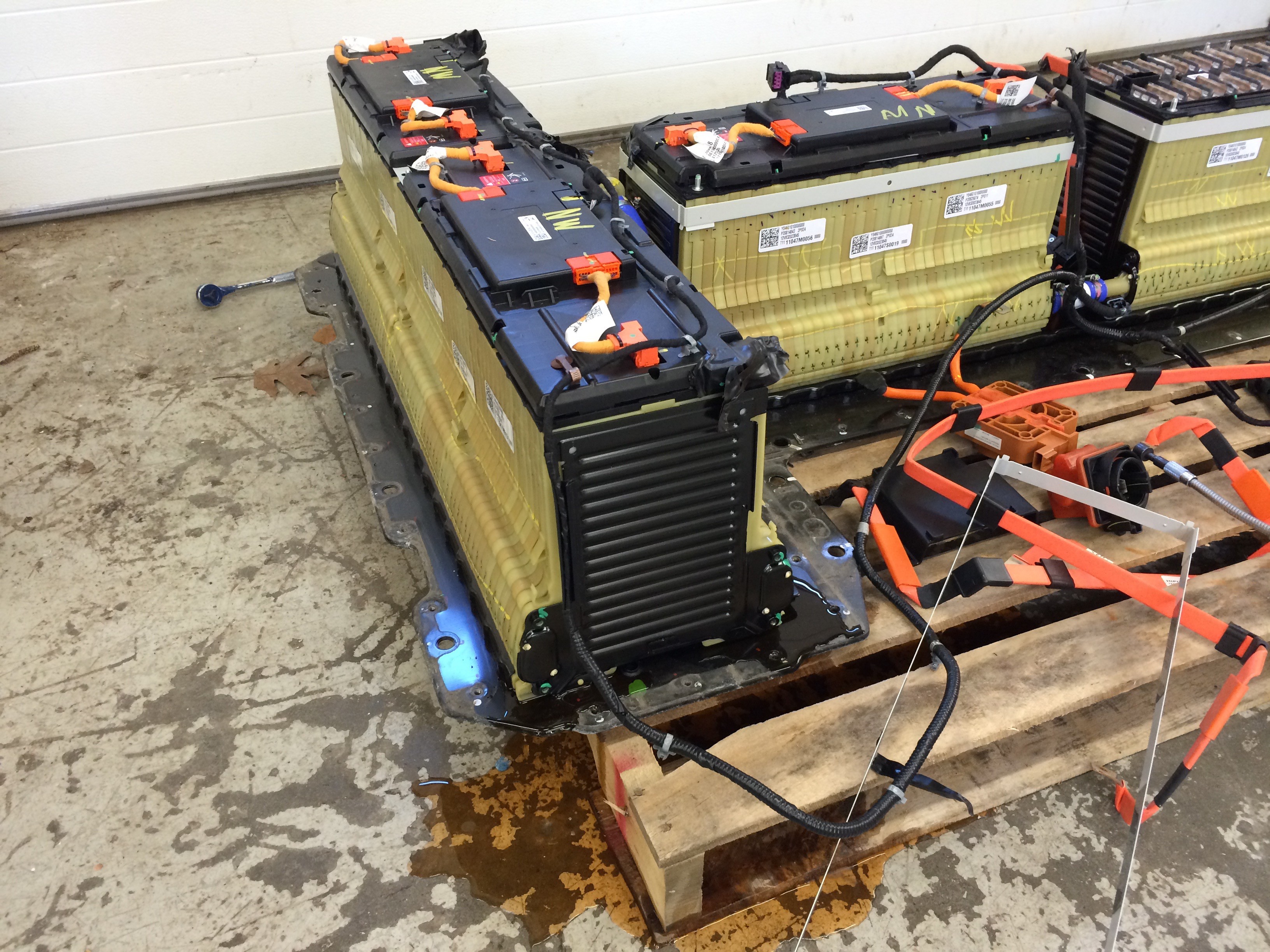
Here are the three packs as they come off of the T-shaped metal plate. I don't have a picture of the hardware that holts them in place. It is a bar on each on at the base that bolts down and clams these plastic cell housings to the metal plate.![]()
Now I'm stuck with the task of figuring out where these modules can fit in my car... woof. The biggest one is 33.5 inches long. My trunk could hold that one I guess. The next larges is nearly that long with the coolant pipes coming off each end. I think I can fit that under the hood above the motor. The small pack will just go in the passenger's lap.![]()
-
A quick switcheroo
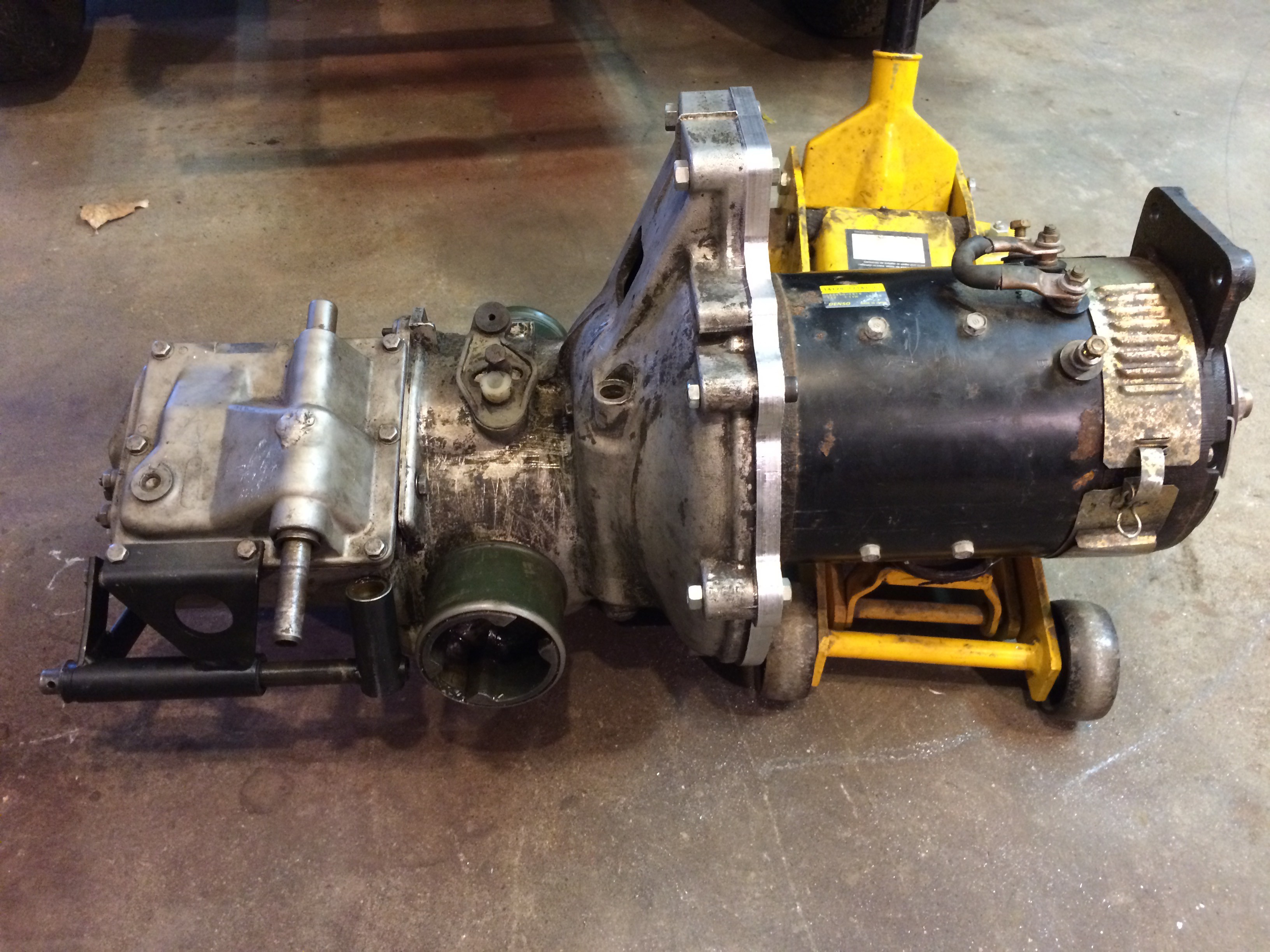
04/12/2016 at 16:24 • 0 commentsI've been trying to set up the Electric Sonett with a smart car motor and controller. I'm putting that idea on hold because I'm graduating in three weeks and I want to drive it down the isle to receive my diploma. Instead I'm temporarily going low tech. I'm talking brushed DC forklift motor with upgraded brushes. Kelly controller 144 volt 500 amps. Used Chevy Volt battery pack rewired to deliver! Still need to figure out the charger situation. I want a Manzanita PFC40XM but it's not quite in the budget. We'll see what I can come up with.
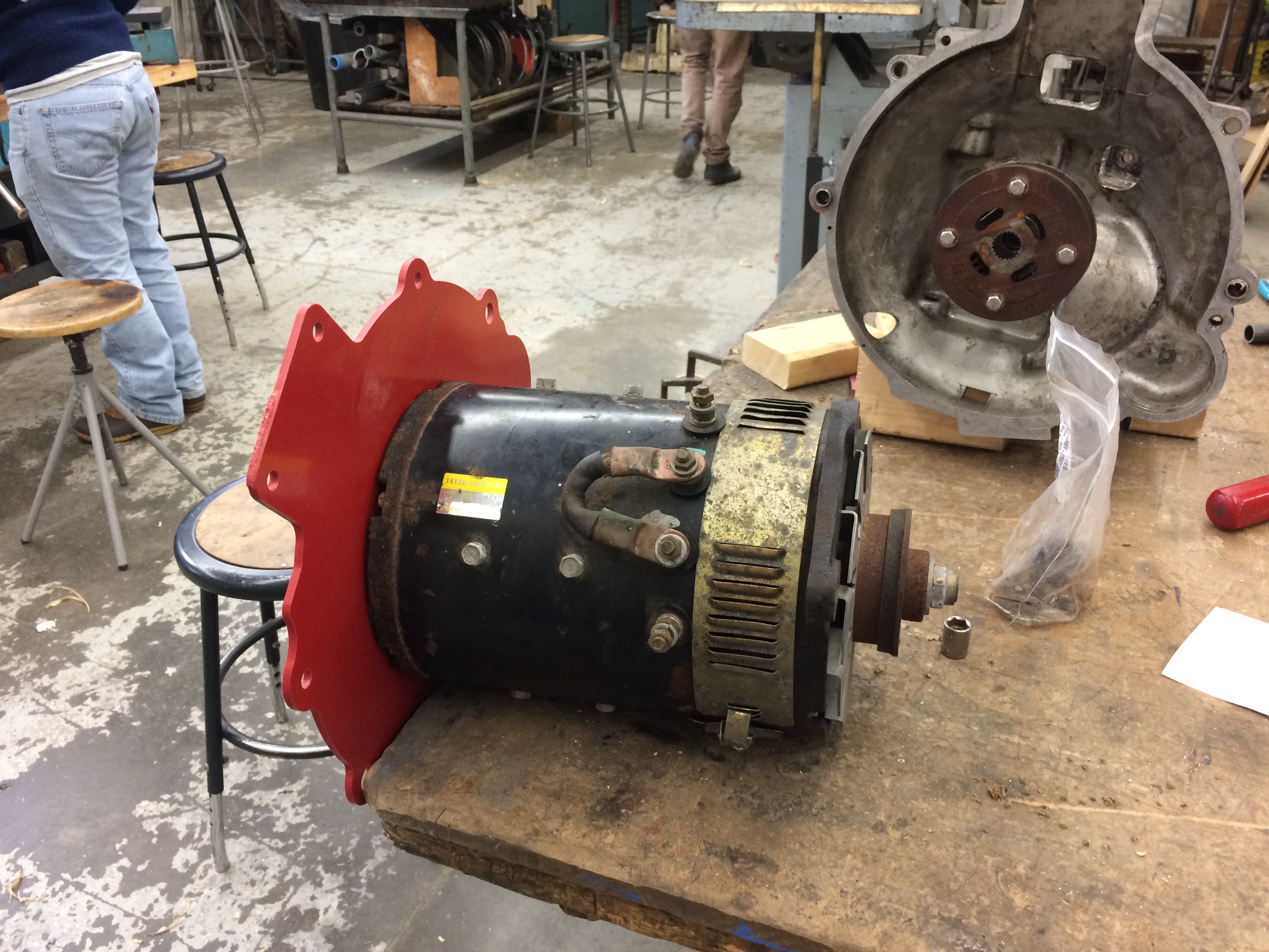
I built the hardware to hold the motor in place over the weekend. Adapter plate and engine mount. I'm going to cob together an adapter between the motor and tranny driveshafts.
This junk will probably only be safe up to 40mph, but it's quick, dirty, and a lot of fun!
![]()
![]()
![]()
![]()
![]()
Electric Sonett: Old Car/New Tech
This project focuses on ecological sustainability and social responsibility through reuse. Increasing lifecycle efficiency, decreasing cost.

 Mount to this surface. Triangle and tab
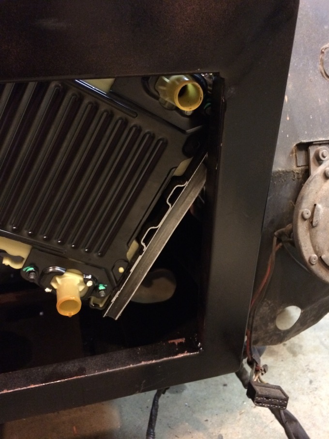


 Here's the batteries resting in the engine bay above the motor and transmission. See any problems? I'll make a metal battery mount that bolts into the engine bay and tranny/engine mounts.


 These huge bricks are held together with glue, steel bands and 3 foot screws. I wanted to see what the cooling system was like so I started taking this apart down to cell level. As soon as I loosed the 4 bolts that hold the black endplates together coolant started leaking out from every cell. Here's what the 4 bolts look like.