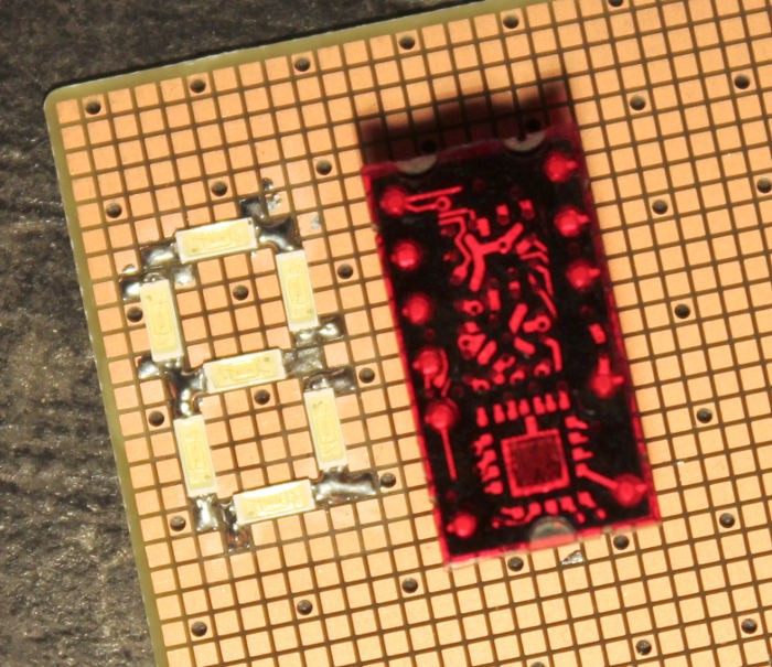
Never seen breadboards like this before (from @Yann Guidon / YGDES's https://hackaday.io/project/8121-discrete-yasep/log/27617-hexadecimal-7-segments-display-continued/discussion-40001):

The breadboard gave me an idea...
I usually like to work with through-hole parts on through-hole-plated double-side boards. But sometimes it's necessary to throw in a SMT part... One hack-job method I've seen (and have been using, when necessary) is to literally cut normal pads down the middle... That works surprisingly well on single-sided boards, but for double-sided through-hole-plated, you've got to also drill-out the through-hole-plating. Not a big deal, really (do the drilling-out first!) The hard part is cutting those pads down the middle, and do-so without ripping 'em off the board. And if you have to do a 16-pin device, that means 8 annoying cuts... What if the cut was already done?
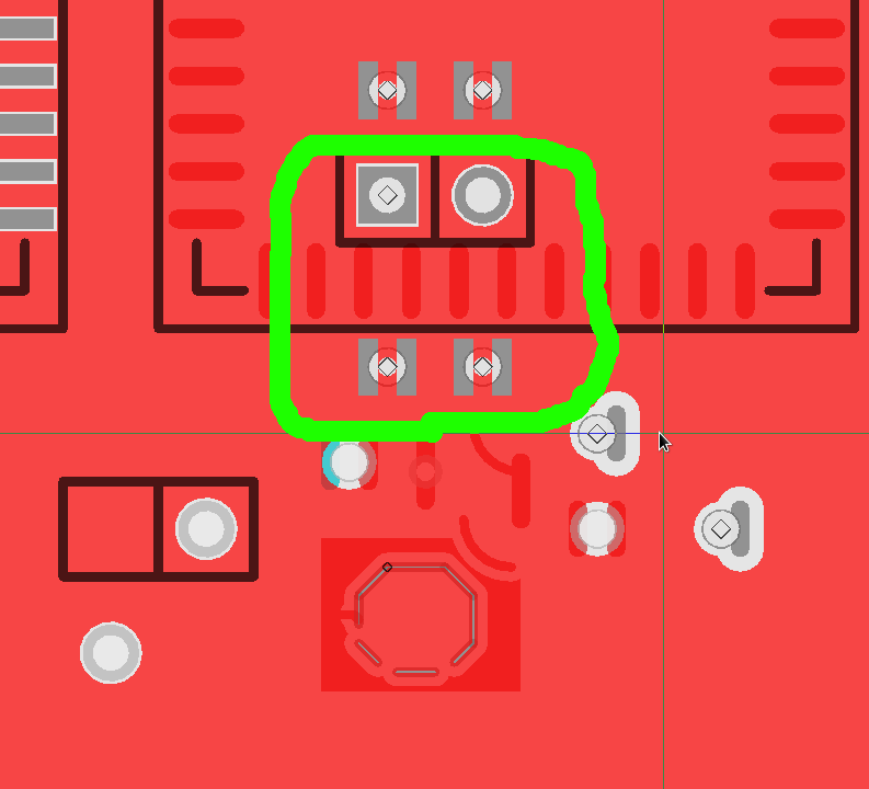
This is some *really* early experimenting...

With surface-mount, the only necessary step is to first pre-drill the through-hole-plating. With the right drill-bit and a handle, this can easily be done by hand.
Some percolating thought-points:
Board-fabs seem to have differing/unspecified handling of THP vs non-THP holes. Especially with regards to holes that have no annular-ring (the bit of copper "pad" that surrounds a hole). So, the hand-drill bit would have to be big enough to rip that up, as well. (Or use another oversized bit as a countersink?).
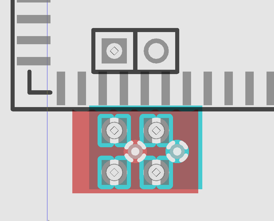
I also can't seem to figure out how to create surface-mount pads that are oddly-shaped... I'd prefer something more like half-circles, so vias can be placed diagonally between each .1in hole, while still allowing for current-flow on the two "planes" (usually ground and power):

But, it looks like it might work! I just grabbed the first part from the default libraries that had .05in spacing, it happens to be PLCC, which I seldom use... though it does make me wonder about whether something could be done for differently-directioned surface-mount pads...
And, then, there's also some consideration about higher-density SMTs... Maybe it'd be plausible to run four per normal DIP pad for 0.025in, but, the middle-pads would be cut-off by the hole... so, not sure yet. I'm obviously not opposed to point-to-point wiring on prototypes...
The same, then, would go for other spacings... but obviously those would have to be on a different area of the breadboard... Trying to keep this general-purpose, as well as versatile, yahknow.
Anyways, for only a couple hours' experimenting... it's looking promising!
 Eric Hertz
Discussions
Become a Hackaday.io Member
Create an account to leave a comment. Already have an account? Log In.
Those SMT breadboards are available at mouser and amazon among other places. Amazon's are "prime"-able for free 2 day shipping. It's not consistent whether amazon, mouser or any of the other vendors are less expensive without counting shipping.
Are you sure? yes | no
Cool, thanks!
Are you sure? yes | no