(If anyone wants to host the 24MB PDF datasheet, lemme know! Apparently google-sites doesn't handle files that large(?!). I OCRed it, albiet not very well... but it's at least searchable, now...)
So, it would seem, random unreliabilities on boot was (mostly) due to a very important but overlooked fact:
Despite the ability to interface directly with 8-bit devices*, the 486 expects to read those bytes one-by-one on the 4-byte data-bus, aligned as such**:
ByteAddress%4   Data Bits
0               D7-0
1               D15-8
2               D23-16
3               D31-24
*Section 10.1.1.1: "The Intel486 processor includes bus control pins, BS16# and BS8#, which allow direct connection to 16- and 8-bit memories and I/O devices"
(Hah! "Direct" my a$$!!)
**Table 10-4. "Data Pins Read with Different Bus Sizes"
(This has been cut-down to only show 8-bit transactions with one ByteEnable active):
BE3#  BE2#  BE1#  BE0#   with BS8#
1     1     1     0      D7-D0
1     1     0     1      D15-D8
1     0     1     1      D23-D16
0     1     1     1      D31-D24
Actually, if I understand correctly, each transaction *starts* as a 32-bit transaction.
(Unless, maybe the instruction itself is accessing only 8 or 16 (or even 24!) bits of memory.)
Then, the device (or chipset) immediately responds with an indication of the bus-size (if smaller than 32-bits), at which point the processor only reads the bits that would be valid in such a case, then will request the next byte(s) as necessary. So, e.g. if it's looking for 32-bit data (aligned at Address%4==0), it'll first send ALL ByteEnables active: BE3#-BE0# = 0. It will ask for all 32 bits it's looking for. Then the 8-bit device will tell it "sorry, I'm only giving you the first byte", and it'll read that one, then request the second byte, and so-on.
So, technically, each transaction is started with no knowledge of the device's bus-width.
(And, oddly, the datasheet actually mentions the odd-case where, say, a device might actually switch the number of data-bits it can supply in the middle of a (32-bit or less) non-burst transaction. Weird?)
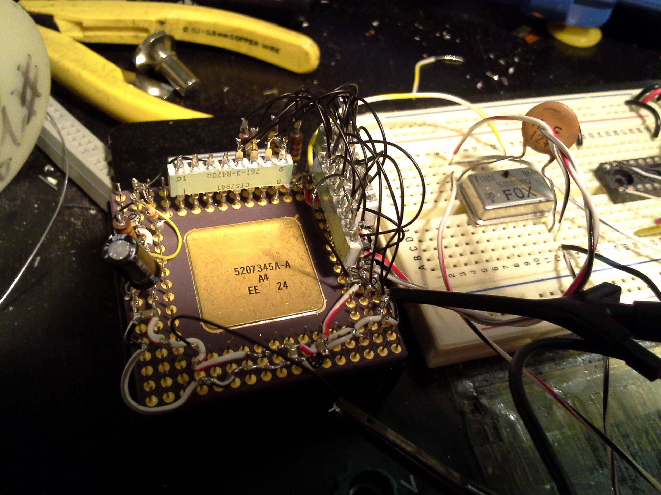
Anyways, the end-result is thus: I had already wired D7-D0 for NOP (10010000) via pull-up and pull-down resistors, before I discovered the above, later in the manual... So, now, I had to wire-up D31-D8, as well, each byte with a NOP. At first I was planning to use pull-resistors as with the first byte... but after much procrastination it occurred to me *why* I was procrastinating: What if I want to change the instruction later down the road...? Yahknow, maybe eventually hook up an actual memory-device (ROM? again CRAZY!)... Simple Solution: Instead of pulling the remaining bytes straight to VCC or VSS, instead pull them to D7-D0.
And then... that's still a LOT of resistors... so had another crazy idea, resistor-networks.
 I used straight-through DIPs, and bent the pins straight out the packages...
So, now, each bit in each of the four bytes basically looks (roughly) like:
      V+
       ^
       |
       /
       \  10k
       /
       |
D7 ----+------.
       470    |
D15 ---/\/\---+
       470    |
D23 ---/\/\---+
       470    |
D31 ---/\/\---'
(Values were chosen somewhat arbitrarily based on what I had laying 'round...)
Or:
D6 ===========+====.
       470    |    |
D14 ---/\/\---+    /
       470    |    \ 10k
D22 ---/\/\---+    /
       470    |    |
D30 ---/\/\---'    V
                  GND
There're a couple cases where the resistor-networks were so long they impeded upon other surrounding pins, including in some cases a bit on the first byte, so we have, in those cases, something like:
       ^
       |
       /
       \  10k
       /
       |   470
D7 ----+---/\/\---.
           470    |
D15 -------/\/\---+
           470    |
D23 -------/\/\---+
           470    |
D31 -------/\/\---'
So, it was a bit of a crapshoot whether the loading of all those pins would interfere with the read-values, but it seems alright.
So, at this point:
It seems to "boot" reliably... As long as I let the power completely drop to 0V when switching off, before switching back on. (Hey! Maybe I don't need a schmitt-trigger nor D-FF on my reset after all! Nor gating on the clock! Awesome! Though, 24 resistors was a bit annoying...).
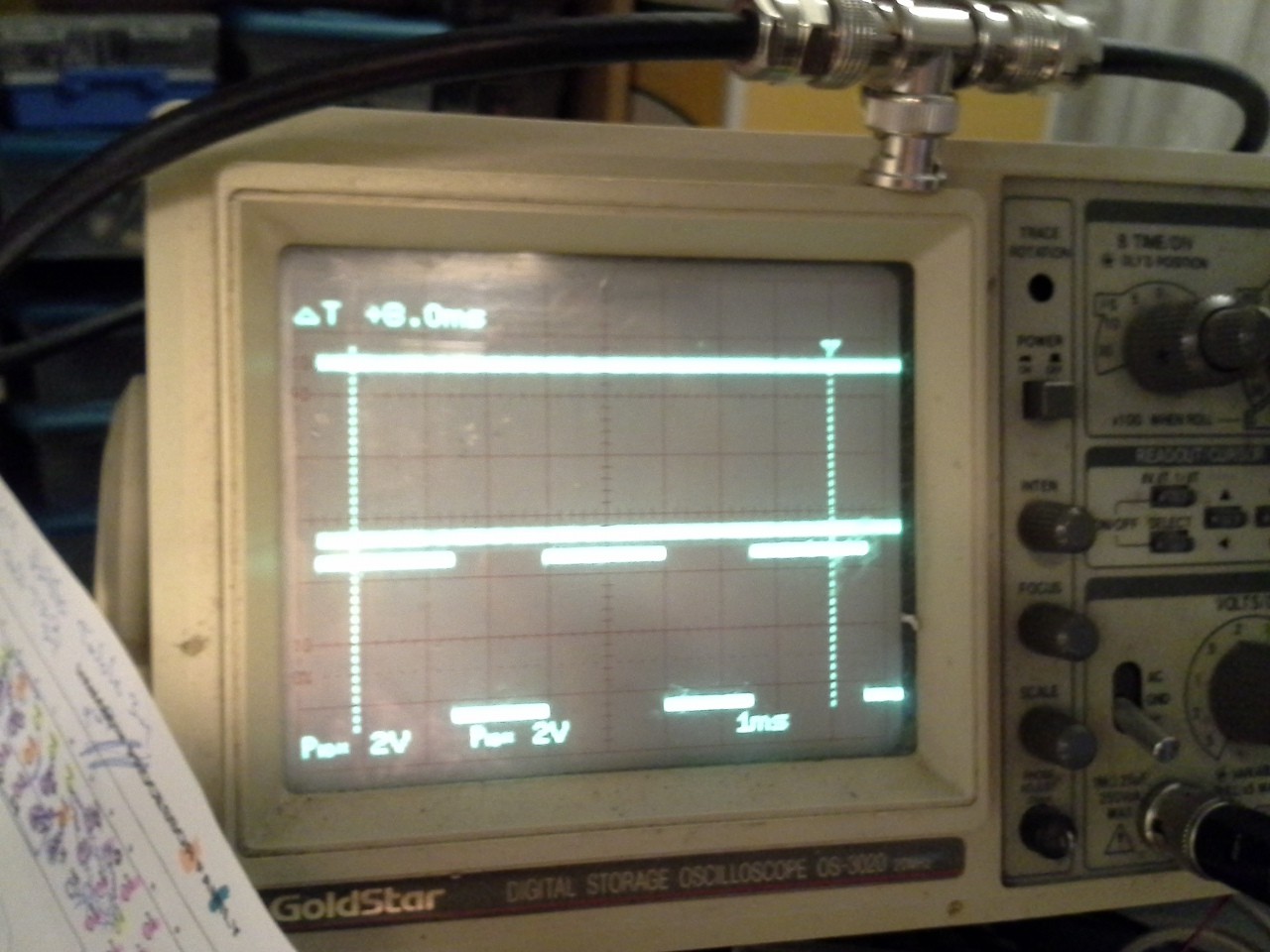
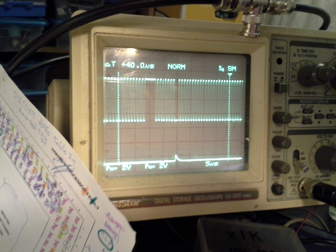
Its functionality seems pretty consistent; it seems to cycle through addresses as expected. But there are some remaining oddities. Didn't bother to check A27 first, this time, as I did last time, since I'd read somewhere that upon reset it only accesses the first 1MB, then wraps(?). But I did check A17, which should be in that 1MB realm... and Nada. Went down from there and noticed A14 isn't square:

Then A12 is even weirder:

And, sure-enough the processor is still driving the data-bus at some point or another...

So, this "project" doesn't really have a particular direction... as it is, this is kinda cool.
- I could start experimenting with really low speed clocks... (Was thinking about maybe making an arbitrary-clock-generator, maybe via PIC or AVR? Could be a useful tool to have 'round)
- I could look into the non-1MB wraparound issue (Likely will lead into figuring out why the processor is taking the data-bus... Probably will lead into learning a lot more about the architecture)
- Could look into delaying the "Data Ready" signal, e.g. for pushbutton-stepping, and-or slowing the "counter" (address-incrementing) via an R/C-delay
- Surely more, but I'm drawing a blank at the moment...
But I could definitely do with some blinking, soon!!!
 Eric Hertz
Discussions
Become a Hackaday.io Member
Create an account to leave a comment. Already have an account? Log In.
Nice work figuring it out, would not have guessed they used an obtuse method like that to transfer 8 bit words on a 32 bit bus.
My first thought for a direction would be to make a very short assembly loop that does some sort of useful work, and have the instructions run from a diode array ROM. That would keep with the idea of discrete components hooked directly to a CPU. But I guess you'd have to use 32 bit instructions to have more than one... that would be a lot of diodes. :/
To stick with 8 bit you'd have to write a program that used 4 of the same instruction in a row, and then 4 of another etc.. That's getting into some crazy demoscene stuff heh
For blinking lights perhaps just hook up an 8x8 led grid via 7400 drivers to a portion of the addr bus; perhaps it would look interesting in its current glitchy state.
Are you sure? yes | no
Hah, interesting concept, diode-based CPU instructions! The weird reading-method is for 8-bit transfers... so there's the inherent fact that it doesn't pay attention to the other bytes. So, actually, your idea would work with 8-bit "diode-ROM" by connecting all the bytes together, as I've done already :)
Also, since it's backwards-compatible with the 8086, if I understand correctly, it should work with 16-bit instructions (loaded as two 8-bit transfers).
Hmmmm. I kinda dig it! Maybe, at the least, the first instruction (which should, allegedly, be "jump"), but actual running code would be great!
And an LED-matrix could be interesting, somehow I'm picturing a gradient, if it was working normally, but I'm not sure that makes sense.
Thanks for the ideas!
Are you sure? yes | no
So when do you start your PC company ? "International Computing Heaters" sounds great.
Are you sure? yes | no
Only if you use these vacuum tube diodes for the ROM. :)
https://upload.wikimedia.org/wikipedia/commons/thumb/4/4d/Fleming_valves.jpg/800px-Fleming_valves.jpg
Are you sure? yes | no
So you are uncovering some of Intel's old dirty secrets :-D
Are you sure? yes | no
Not yet, apparently... The datasheet seems to contain all the information, just that one piece "connect an 8/16-bit device directly" early-on was a bit misleading, but later clarified. I don't think I know enough about the architecture to recognize a dirty old secret if I saw one... well, maybe the bit where it was explicitly stated... about the start-up sequence for the clock-input never having been previously specified. That did sound a little goofy, like they were finally revealing a dirty old secret.
OTOH, seeing as how this architecture has been pretty much a "black box" to me for all these years, the whole thing's kinda like uncovering dirty old secrets... I'm an archaeologist!
Are you sure? yes | no
It reminds me the time I used to crawl inside the datasheets (only 3 books for the P55C) and I discovered http://sandpile.org/ when it was still in its infancy. I think there was another "Intel's secrets" but it was swallowed by Dr Dobb's Journal IIRC. Oh the old memories... but I'm not looking back with nostalgia. I'm glad I don't have to deal with Intel internals anymore!
Have you considered using a DEC Alpha ? ;-)
Are you sure? yes | no
@Yann Guidon / YGDES, I've never owned an Alpha, but I do remember having one in the ol' computer-lab that I think was 500MHz when the rest of the lab was topped-out at 33MHz... I think the file/apps server was *maybe* 66MHz. But no one knew how to do the Alpha, and all the lab machines were Macs, anyhow, so it sat unused. I should look into what processor those things used... As I recall 500MHz was nearly 5x faster than any desktop PC at the time.
I have an SGI mobo in the scrap bin that I'm half-tempted to remove the chip from, next... MIPS is something I've *sorta* been wrapping my head around, lately. I've also an old SUN board, no idea what its processor is.
Also, found TWO MORE PGA 486 chips (now 4!), in addition to some TQFPs on montherboards, in my collection... so there might be a "32-bit Nopulator 2.0" (Thanks @Xark) coming 'round soon.
Really, though, this whole ordeal was *originally* supposed to be about all those early-early 40-pin DIP processors I've got sitting 'round... that I wanted to make into something at least blinky without having to learn too much of their specifics; alot of 'em didn't even have datasheets online last I checked, but times've changed since then... (I just verified, I had 8088 machines not 8086's way back in the day, but I was thinking 'bout chips even older than those).
But, now... sheesh... who knows where this is going... Never heard of sandpile, thanks for that link, and the other references, as well. I might actually learn a few more instructions besides NOP... Maybe actually look at what the internal registers store... Maybe even attach a ROM, CRAZY!
Your "trace" and "breakpoint" things, without really knowing how such things are typically implemented, led me to think of maybe merging #sdramThing4.5 "Logic Analyzer" into the mix... could easily record several seconds of bus-transactions into a couple SDRAM DIMMs... not sure why, but it's another mulling-over...
Oh, and I have an early-early PPC mobo... hmm...
Are you sure? yes | no
"Nopulator" HAhahahahaha!
More intensive instructions : IDIV, some FP stuff, MUL... multicycle, most are microcoded.
More consumption comes from higher voltage, add 20 or 30% Vcc ;-)
You can also crank it up with resistors on each IO pin so it draws current because the pins don't float anymore. even better : not pull up or pull down but "pull-middle" so the CMOS input gates are driven in "intermediate" state where they are all conducting. For added fun, connect them all to a Vcc/2 voltage regulator through 47 Ohms each. Watch it burn.
The Alpha 21064, 21164 and (hugh) 21264 (EV6) are monsters... Have a look at their local step-down. It has a huge bank of tantalum capacitors.
I have a few EV6 machines and the DS900 was an amazing PC. Too bad their power supplies have a known defect that reboots it randomly... Otherwise I could survive the computer apocalypse with these beasts, but they heat too much and theirs SCSI are too noisy...
Now I use an i5 laptop.
The MC6809 heats quite a lot. Several watts. The faster 68B09 might heat even more. Lovely chip ! I learned REAL PROGRAMMING with them as a teenager. Unfortunately I had to convert to the x86 clan...
For the SDRAM trace, I don't know... I must have a tape of SDRAM chips somewhere but I don't want to bother with dealing with the refresh. OTOH I have a nice stock of 256KB and 512KB async chips at 15-20ns. That's a marginal hit on the processor clock cycle (I hope to reach 150ns per half cycle)
Are you sure? yes | no
Hah! I guess it's pretty obvious I won't likely be connecting anything wider than 8-data-bits to this beast... I dun think I could reach my soldering iron under those Network Resistors...
Are you sure? yes | no