-
Transistor Oddities II - I FOUND A USE!!!
01/16/2017 at 19:18 • 6 commentsUPDATE IV: Adding an image of the differential-amplifier simulation.
UPDATE III: DEFINITELY a current-mirror. Check out the bottom.
UPDATE II: Throwing random images and notes up at https://github.com/esot-eric-test/transistorOddities
UPDATE: Isn't this a [single transistor] current-mirror? Gotta explore this in a bit more depth... Some notes at the bottom.
--------------
Split The Current, and switch it from one side.
![]()
![]()
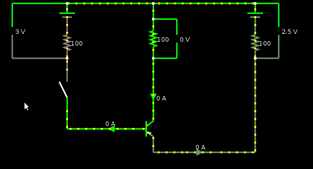
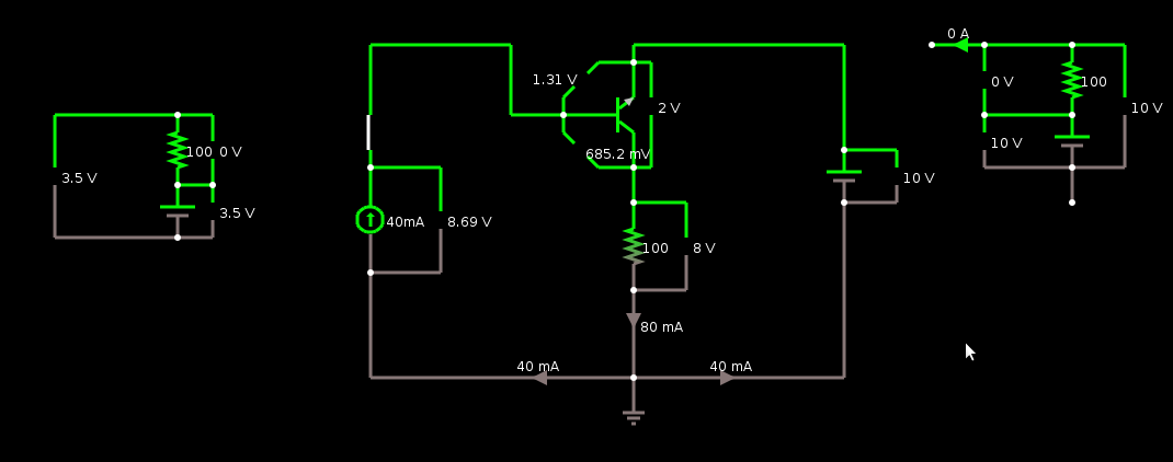
So, imagine we have two 3V coin-cells with slightly different charges, or two solar-cells which may receive slightly different amounts of light, and want to draw darn-near twice their maximum-rated current.
Putting them directly in parallel isn't so smart, right? Especially when the system's powered-down.
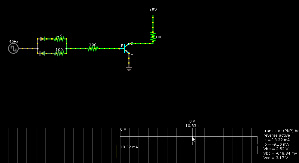
So, with this circuit--using a PNP on the ground-side, or an NPN on the positive-side, with its emitter tied to ground/positive, respectively--roughly half the current comes through each coin-cell, and the on/off switch (or maybe another normally-wired transistor?) controls them both.
So, here I'm simulating two coin-cells; one's at 3V, and one's at 2.5V, when unloaded. But their internal series resistance is roughly 100 ohms (represented by the 100 ohm resistors on each branch).
In the middle we have a load (a circuit, LED, etc...) simulated by another 100 ohm resistor, getting about 1.5V.
The switch could be anything, maybe a "normally-wired" transistor controlled by a pushbutton and flip-flop as part of the load, etc.
Note the directions of the current entering/leaving the transistor... Current is *exitting* the PNP's emitter, and *enterring* its collector. That's why this guy's a weird setup that's been boggling my mind for weeks.
---------
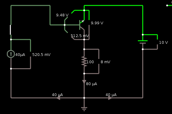
Here's the original weird circuit:
![]()
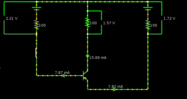
And here's another, in a more logical topology.
Note that as long as the right-side "battery" is greater-than or equal to the right-side "battery's" voltage, the two branches carry the same current. Doesn't that make it a single-transistor current-mirror? Hmmm...
-----------
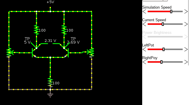
DEFINITELY a current-mirror. Have never heard of a single-transistor current-mirror, have you?
![]()
![]()
Not that we can trust simulations...
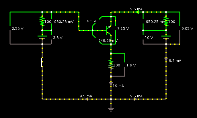
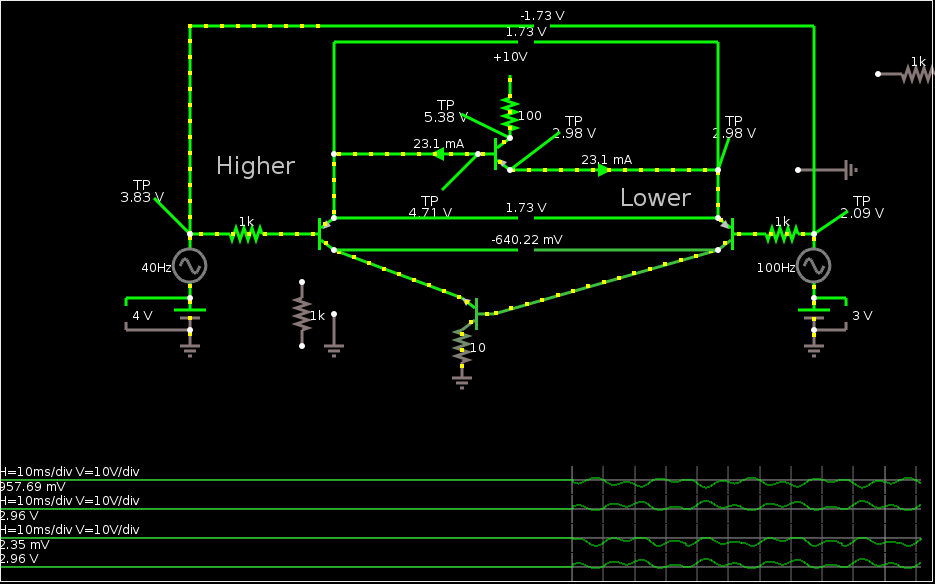
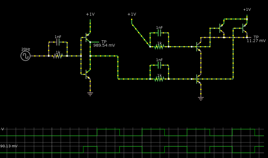
Here's a simulation of an attempt at a differential amplifier using this current mirror. It *sorta* works. Though I know little about diff-amps, these days...
![]()
-----------
If you haven't been following the saga, check out The mistake that started it all, and Some more rambling.
-
Transistor Oddities
01/15/2017 at 09:34 • 11 commentsUPDATE V: Here's a demo using a TTL input as an example of my original "weird circuit" in use
Note that by varying the input-voltage to greater than about 3.65V, the circuit's very similar to mine, current flows from the base through the collector. And at nearly 5V, current flows into the NPN's emitter.
UPDATE IV: I FOUND A USE for the weird PNP mistake!
--------------
UPDATE III: Found a REALLY HANDY REAL-TIME-ish SIMULATOR
![]()
and more simulation-links at the bottom.
UPDATE II: New Interesting circuit, at the bottom.
UPDATE: ROTFL, it's just diodes... more at the bottom.
---------
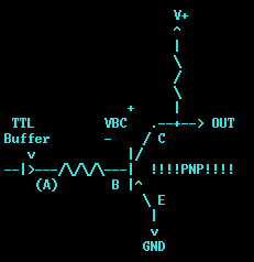
Over at #Improbable Secret Project, (Log: https://hackaday.io/project/18868/log/50780-open-collector-fail-the-atx-power-switch-saga-continues) I accidentally discovered that the following circuit is possible:
![]()
The key-factors are:
- Transistors work similarly when C and E are reversed (though with tremendously lower current-gain)
- TTL ... nah, that isn't really relevant, after all.
So, what we have, here, is a *buffer*, rather than an inverter, as it would be with the NPN I'd intended to use.
It's sort of an emitter-follower, except using the "key-factor" this makes it more of a "collector-follower."
(BUT, allegedly that term is reserved for another purpose.)
Note that when the input voltage is greater than (V+ - 0.6V) (high, assuming VBC-on=0.6V), the transistor is *off*.
When the input is less than (V+ - 0.6V) the transistor is *on*, and the output-voltage follows the input voltage... So, a 0V input would result in a 0.6V output (which is lower than a TTL circuit's VIL-max of 0.8V, nice) so it will be Low.
Similarly, a TTL circuit's VIH-min is something like 2.0V, and obviously VOH-min must be greater than that. So, feeding 2.0V into the input, the transistor will be on, but its output-voltage will be 2.6V... High.
(Of course, these depend a little bit on the value of the base-resistor)
----------------
Well, here's an interesting result...
![]()
This is an AND gate, I think!
I'm calling it a [L]AND gate, because, without the pull-up resistor, it's an AND which only outputs the Low state, the "high" state is determined by the load (the pull-up resistor, in this case).
Similarly, if I've got my logic right, the opposite (using NPNs connected to V+), creates a [H]OR gate.
I'll stick to discussing the [L]AND gate...
When both inputs are the same, we have the same effect as with a single transistor... That takes care of the 00, and 11 states of an AND gate.
What when one input is "high" and the other is "low"?My THEORY (untested) is that the lower of the two inputs will be followed.
The reality may be significantly different... Since the current-gain is really low (like IC=2*IB), and since the high input would imply a higher current going into that transistor's base, that transistor (the one pulled high) will have a greater IC... and this is where I can't quite wrap my head around it... because a higher IC (through B) would create a greater current through C->E, which would cause it to pull even lower. Hmmm...
So, I think it's an AND gate, but I'm not certain.
------------
This came as a result of analyzing @Ted Yapo's circuit from #CBJT Logic:
![]()
Note the normally-biased PNPs Q9 and Q10 in that circuit form a NAND gate. Which seems a bit backwards, since they're in parallel. But if the other transistors were removed and replaced with a pull-down resistor (and if this were 5V logic), then we'd have essentially the exact opposite of the [L]AND gate... they'd be a [H]NAND gate.Now, I find it a bit strange that two *parallel* transistors could create an AND (or NAND) gate... OR, sure. NOR, sure... So I took a bit to think about it and, here's my conclusion. NAND is actually the same as an OR which has its inputs inverted.
      ______
-|>o--\     \
      | OR   >---
-|>o--/_____/

    =
      ______
-----|      \
     | NAND  |o--
-----|______/
Unfortunately, it doesn't seem [to me] too simple to interface a [L]AND and [H]NAND gate such that the series transistors (and pull-resistors) could be removed... but I could be mistaken. Maybe somehow within Ted's 1V logic...?
But, there enters a new problem for the [L]AND gate... its output is Low=0.6V minimum, but if I understand correctly, in CBJT logic, that'd actually be a *high*. And, further, the [L]AND's output is highly dependent on the load... its being pulled-up via resistor means the resistor supplies the current to the next stage when the output is low, not the transistor... which means despite its output being low, the current is flowing *out* of the "output". which means it can't pull another transistor's base low, right? And might not even work with TTL inputs (which are NPN emitters)... And, again, here's where my head starts spinning.
---------------
Update: I dunno how I didn't see it before... basically my circuits are nothing more than diodes...
![]()
----------------
Here's an interesting one for yah, from @Yann Guidon / YGDES
What's this do? (Answer in the comments! Scroll-carefully if you don't want the spoiler!)
![]()
(Hmmm, might not need the resistors on the inputs)
--------------
Here's a simulation of one of @Ted Yapo's #CBJT Logic inverters.
And here's a simulation of his NAND circuit
![]()
These screenshots don't do it justice... The little dots in the wires move to show the current-flow, which is quite handy in viewing this circuit's functionality.
I'm not sure I'd use this to do simulations of nitty-gritty details, but for demonstrating fundamental concepts it works really well.
------------
Here's the "fundamental concept" that I couldn't wrap my head around, with the PNP and its emitter tied to ground. Actually, this demo shows what's happening, and it isn't "just a diode" after-all! Too bad it doesn't export animated GIFs... so click that link, if you're curious.
![]()
-
Extracting Images
11/19/2016 at 07:40 • 0 commentsHeh, another unpublished draft from half a decade ago...
...
Poor @Ted Yapo's log over at #Bullet Movies has been flooded with my random-thoughts... https://hackaday.io/project/18138-bullet-movies/log/49192-more-frames/discussion-69834
So I'mma move 'em here.
His brilliant idea is to simulate a high-speed camera by making use of the Red, Green, and Blue sensors in a typical camera at separate times... strobing the scene with Red Green and Blue LEDs sequentially.
The idea, then, is by strobing them bright enough and fast enough, he might be able to achieve up to 1million stills per second...
(WHOA!)
Concept *definitely* proven, his initial experiments look great.
But...
So far, only 3 frames, total...
So, then, the question has arisen: can he squeeze more than 3 frames out of it?
--------
To which, my thought is, there must be a way to get a few more frames by strobing the LEDs in simultaneous combinations, as well. (E.G. strobe Red and Green simultaneously).
......
Logically, as Ted's pointed-out, there's, essentially, "three equations" and thus only "three unknowns" can be derived... The three-equations being those of each color-channel. While this seems logical, there seems to be a ton more possibility here, somewhere buried within knowledge of how the system samples, etc...
...
And, frankly, now that I'm writing this, I've a vague feeling quite a bit more can be derived from this knowledge... but I can't place it.
...
So, where I was at *before* I started writing this up... was that there're *definitely* some additional "equations" that are easy to set-up...
When the system's set-up with a tripod, and calibrated exactly as it will be during the image-capture, then one could take photographs of the *empty* image, before-hand...
........
-
Audio Amp Motor Driver - motor polarity oddities + parallelling experiments TODO
03/22/2016 at 10:14 • 2 commentsCrazy Update some five+ years later, at the end....
....
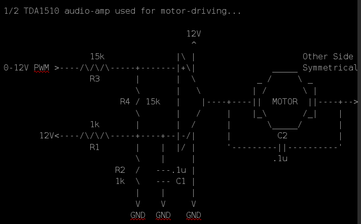
The Class-AB (linear) audio-amp chips I'm currently using for my motor-driver (see past logs) have *4* channels... So, for low-enough-current motors this single chip could handle *4* separate DC-motors. (cool).
Update-Wise: it seems to be working quite well for several weeks now. It definitely gets warm, and maybe on a few occasions has been dropping-out (plausibly due to thermal protection-circuitry combined with the fact the heat-sink it's attached-to has a *channel* (for screws) right under the thermal-pad...). But actual overheating-protection seems few and far-between.
There is a more pressing problem that oddly seems to be related to the motor itself... when spinning in one direction it works fine, but in the other direction it acts a little strange, kinda stutters. This only seems to happen when driven at full-speed (when the amp's outputs are close to ground and V+).
Now there's a few oddities, here. Watching the negative output from the audio-amp, it's very clear that that output stutters *with* the motor's stuttering... When it's *just above* ground, it runs smoothly, but when it stutters, the output actually reaches ground. OK, maybe thermal protection...
But then, there's oddity 2. When the motor's *loaded*, it doesn't do this. The output doesn't go to ground. When it's *loaded*, the motor draws *more* current (right?) so then thermal-protection seems illogical.
OK, now there's oddity 3. As I recall, reversing the polarity of the motor's connection to the audio-amp/motor-driver doesn't do what I expected. I expected the motor to continue to "stutter" when the motor-driver is driven the same way (now, the reverse-direction), thinking the "motor-driver" might be a bit 'biased' toward one polarity over the other (maybe one of its channels has a slightly more-powerful low-side transistor than the other channel?).
In fact, what seems to be happening is that the motor itself is responsible, when powered with one polarity over the other. Is that plausible? I should measure its current-draw... But, again, loading it causes the stuttering to *stop*, so a differing amount of current-draw doesn't seem like the problem, right...?
The motor is from the 1980's, so it's likely had years of wear... maybe it was used in one particular direction more than the other, so its brushes aren't worn evenly, or something...? Is it possible that the sparking caused by the brushes' breaking-contact with the windings could be larger in one direction than the other, (again due to wearing) causing, maybe, over-voltage protection?
Again, the weirdest part about it is that when I actually apply a load to the motor's shaft, this problem isn't a problem. When I drive the audio-amp's input such that the outputs aren't *quite* at their limits, it's also not a problem. BUT it only seems to happen when the motor's powered/spinning in the same direction (but not the other), regardless of the polarity it's been wired to the driver-chip.
Oh, and, yes, I did (early-on) throw in freewheeling/flyback diodes, despite my experimentation-goals of seeing whether the Class-AB amp really needs them with its push-pull abilities.
------------
Now, onto the experimentation-TODO:
It was suggested, if I understand correctly, at https://hackaday.io/project/9919-powerful-portable-speaker/log/34102-talking-about-circuits that Class-AB amps might be paralleled?! OK, I've always thought this to be a bit risky, since it'd be hard to have two identical transistors/gains, etc... So then the loading on one output would be higher than the other... (and maybe worse in this particular case, since the gains are fixed, there's no [external] feedback-path, they might differ slightly). But, maybe it's actually possible... and something worthy of my looking into. Here's a good start: http://cds.linear.com/docs/en/design-note/dn126.pdf I found some other resources, as well, but one was about Tube-Amps, and the other was nothing more than SPICE simulations (which seem to me like they wouldn't take into account differences in silicon).
Also, per more discussion at #Powerful Portable Speaker, with @HP (who apparently can't be '@'ed without insider knowledge) and @Moritz Walter:
http://www.ti.com/lit/an/snaa021b/snaa021b.pdf
http://www.shine7.com/audio/pa100.htm
http://www.shine7.com/audio/jeff.htm
https://en.wikipedia.org/wiki/Bridged_and_paralleled_amplifiers
Are these for Class-AB...? More importantly, maybe... Are my chips Class-AB? I need to refresh myself on the classes!
And... Again, the commentary at: https://hackaday.io/project/9919-powerful-portable-speaker/log/34102-talking-about-circuits wherein @Moritz Walter's log-entry--largely regarding charging batteries in series, which could be quite helpful down the road--has been hijacked. Apologies-yo!Why...? Would there be any benefit to using the four channels of a single chip to drive a single motor...? If overheating's the concern, then wouldn't it just redistribute the heat around the same piece of silicon, and ultimately generate the same amount of heat on that same piece of silicon? I don't know. Another plausibility is using separate chips to redistribute that heat. Or maybe there'd be some benefit besides heat... I don't know. I guess that's where experimentation is worthy. I'd throw out there that the effective "on-resistance" would be lowered, but that doesn't make sense in a Push-Pull Linear-output... right?
-------------
Anyways, this has been my go-to circuit for motor-driving since I started this crazy endeavor months ago, and it seems to be working surprisingly well. Maybe I should do a full writeup/schematic. Chip-wise, we're talking the TA8251AH.
........
August 2022:
........
These dang chips are on sale for *70* chips for $20. 280 motors.
You gotta know I'm having a hard time justifying *not* making this purchase. Even if all I used them for was driving every "toy motor" and cassette motor and every itty-bitty bipolar stepper from floppy and CD drives in my collection, attaching nothing to their shafts but a piece of tape. Heh!
Or, do I really need all that fancy circuitry from before? What was wrong with simply using AC-coupling and an RC-filter? Or even dropping the RC filter and using PWM at low frequency?
...
Actually, having vaguely-remembered the parallelling findings, here, I kinda thought about making a "pure-sine" inverter for my oscilloscope... Though, I kinda doubt I've a suitable transformer. And, a brief look through a doc linked here from TI suggest what I initially thought: 'servoing' (with much additional analog circuitry, which I, tend to have bad luck with) is necesary unless the tolerances are *finely* tuned (0.1% resistors, and what about the chips themselves?). And, again, these guys don't have typical feedback pins available. And, well, it'd be an interesting experiment if it wasn't 120V... And, well, I've still 14(?) of these chips unused anyhow...
but... 280 motors!
...
Oh no, more ideas:
These are 4x Bridge-Tied-Load speaker-amps. each BTL output-pair has a single input. The difficulty of all my circuitry in the past logs was due to the fact that input is centered at 0V; the device is, and my circuit was, single-supply.
OK. But using *two* speaker-drivers, one could, maybe, use the non-inverted outputs... Then drive the two inputs separately. Essentially: PWM on one (0V-3.3V) and "Direction" on the other. Single-supply. And could still drive two small motors, or a small bipolar stepper, from each chip.
.... Sheesh, brain!
-
Check The *proper* datasheet!
01/31/2016 at 14:56 • 0 commentsI've been fighting getting this Vacuum Fluorescent 16x2 text-display working...
It's supposedly compatible with standard character-LCD displays based on the Hitachi HD44780...
So, there's a datasheet for *the entire display*: Samsung 16T202DA1 but I found the HD44780's datasheet to be a bit more informative, so have been using it for timing-info...
Things were working fine until I started working with the "Busy Flag." Hardcoding excessively-long delays seemed to work fine, but reading that Busy Flag just resulted in all kindsa fail.
I thought maybe my port-direction stuff wasn't working quite right, since I hadn't done any other read-back from the display, prior. Maybe the data was floating too long, or something. This seemed somewhat corroborated by the fact that whatever *last* value was sent to it *seemed* to have an effect on whether it functioned or not... E.G. *for the most part*, if I sent a character that had bit 7 set to high, then the system would crash while waiting for the busy-flag (which is read-back on bit 7), but if I sent a value that had bit 7 set to low, then the system seemed to work fine. *For the most-part*. There were some other oddities that didn't *quite* align with this logic, but durn-close.
So then I implemented a simple test: I wrote a character to one position, then another character to another position, then read-back the character at the first position, and... it seemed *almost* to work, in some weird way... *almost* corroborating my theory that read-back wasn't quite implemented correctly...
And, eventually, the instructions seemed to get garbled.
I'm using this thing in 4-bit mode... so my thought was that the two-nibble reads were somehow getting misaligned, maybe one was missed here or there, or maybe there was too much noise on the line causing spurious "Strobes"... This could still be true, actually... Apparently the *chip* datasheet says the minimum High input-voltage on the *strobe* pin is *higher* than the data pins, 0.8VCC (4V) rather than 0.7VCC (3.5V). Yet the *module* datasheet says the minimum High input-voltage is the same for all pins, 0.7VCC... and I'm using a 3.6V processor, so... hmm...
But here's a more-glaring thing... The *chip* datasheet *explicitly states* (In *several* locations) that the Busy Flag ALWAYS RETURNS LOW.
The chip is marked: NEC D16314AGJ, the closest-match datasheet I can find is uPD16314... so it may be slightly different. BUT the ALWAYS LOW Busy-Flag definitely seems relevant...
This venture has led me in so many directions, I can't quite piece it all together. I'm certain I saw a recurring case where it seemed that the data read-back was read-back in 4-bit mode with the *same* data in both nibbles... matching almost-identically the last nibble sent. Then there was the case where it *almost* read back the actual data written to the previously-written character, except with one or two bits incorrect... This one worked fine for several seconds, then the instruction-garbling...
If I recall correctly, that was the last test, before I gave up and swapped out the VFD for a regular-ol' *actual* HD44780-based LCD display... which once plugged-in seemed to work *perfectly*... Prompting me to look up the NEC D16314's datasheet... and noticing the blaring statement that the Busy Flag is ALWAYS LOW.
(But how does this explain the *other* issues...? The 4-bit read-backs that seemed to be the last-nibble written, repeated twice...? And the fact that it eventually gets garbled instructions, even though *currently* I'm not actually *using* the busy-flag...? ... would seem I still have some friggin' work ahead of me.)
So, this is for my stupid [Audio-Amp] Motor-Driver Testing Experiments... The intention being to have easily-adjustable settings for things like minimum and maximum PWM values, to choose whether an output is locked-antiphase or direction/PWM, to vary the Proportional Constant (KP) for my positional-feedback-loop, and more...
HOW it's taken *literally* DAYS to get a stupid text-display working is beyond me... This is probably the third or fourth time I've worked on these stupid things and pretty much forced by oddities like these to go the ground-up route each time, despite having the old (functional before!) code at my fingertips.
That's alright, this new code is much more sophisticated; a (reentrant?) state-machine setup to prevent CPU-thumb-twiddling while waiting for things like the necessary delay between writing the "Address" (RS and R/W) and the rising of the strobe (E). These things could be handled by "wait-states" (and DMA!) on this PIC32's Parallel Master Port, but then it wouldn't be nearly as portable... I guess.
#commonCode (not exclusively for AVRs) for the win!
-
Audio Amp Motor Driver - Linearizer Better'n Expected
01/26/2016 at 09:25 • 0 commentsUpdate: EXCELLENT results briefly summarized at the bottom... (Update 2: and a couple more)
The "Groovy Circuit" of the last couple logs is now being tested with an abruptly-varying PWM signal...
0->3.3V PWM (20-80% duty cycle)
                V+
                ^
                |
                \
             R1 /
                \
                |
                +--|>|----.
                |         |
                |       __|__|
                |      | / \   3.3V
                |       /___\  Zener
                |         |
0->3.3V >---||--+--|<|----+----->  >----.
                |         |             | Audio
                \        ===            \ Amp
             R2 /         |             / Input
                \         V             \ ~30k
                |        GND            |
                V                       V
               GND                     GND
Again, the point of this circuit is several-fold.
First, it attempts to linearize the PWM signal, so the motor will be driven by an *analog* value rather than directly by PWM.
Second, it relocates that now-linearized signal such that at 50% PWM the input to the audio-amp is 0V, but at 20% PWM duty-cycle, the input to the audio-amp is now *negative* (without a negative power-supply available).
Third, it attempts to adjust *quickly* to sudden changes in the PWM value... E.G. If the motor's running forward at full-power (somewhere around 80% PWM), and suddenly the system needs to bring the motor to full-stop, the next PWM duty-cycle will be 50% (stop). Ideally, this circuit will respond to that sudden change.
I guess, in a sense, this circuit's output is similar to that of a D-to-A converter of the Resistor-Ladder sort (Thanks @Yann Guidon / YGDES, I get your reference, now), where the DtoA has both positive and negative power supplies. As opposed to, say, the output of an R/C filter...
R/C Filter "Averaging" circuit

0->3.3V PWM >---/\/\--+----->  >----.
                      |             |
                     ===            \ Amp
                      |             / Input
                      V             \ ~30k
                     GND            |
                                    V
                                   GND
An R/C filter wouldn't accomplish near-immediate response to sudden changes in PWM values... e.g. a sudden change, say, from 80% 50% and back to 80% in three cycles would result in almost zero change on the output, whereas the "groovy circuit" I came up with seems to respond almost immediately:
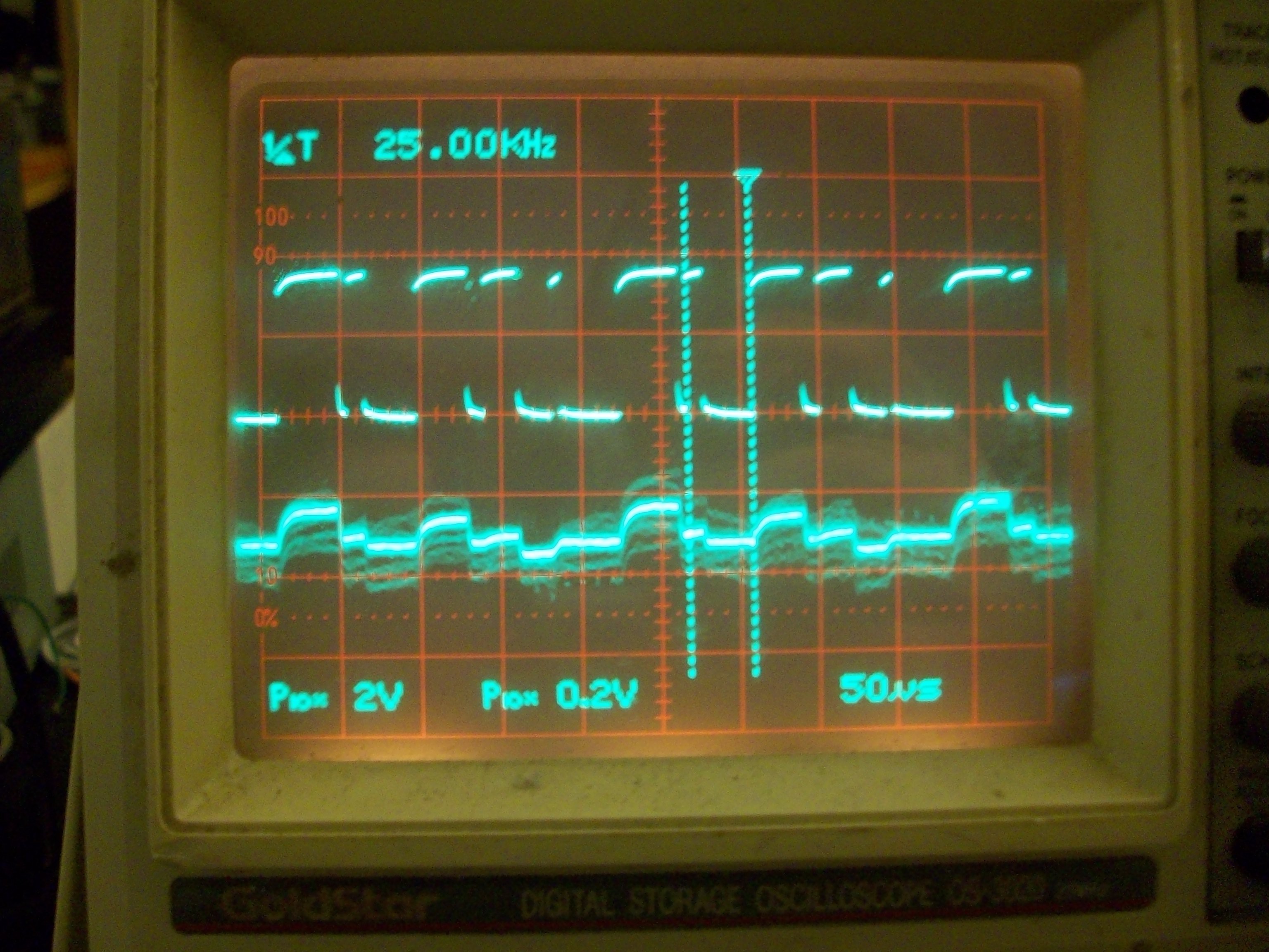
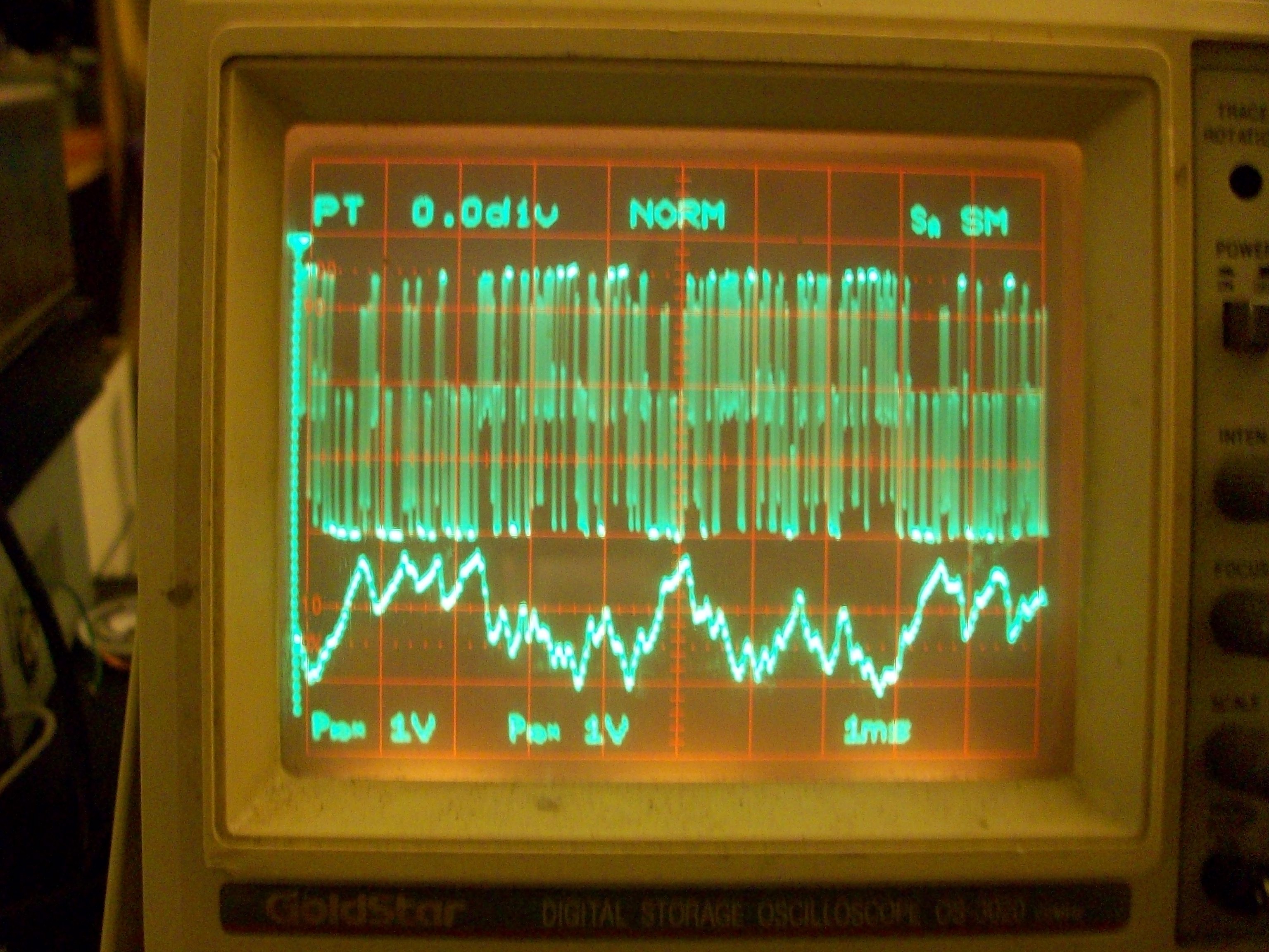
The first trace is the PWM input, varying dramatically in duty-cycle from cycle to cycle.
The second trace is the output of the "groovy circuit." I'm not yet sure where the noise is coming from, this is a *very* early experiment.
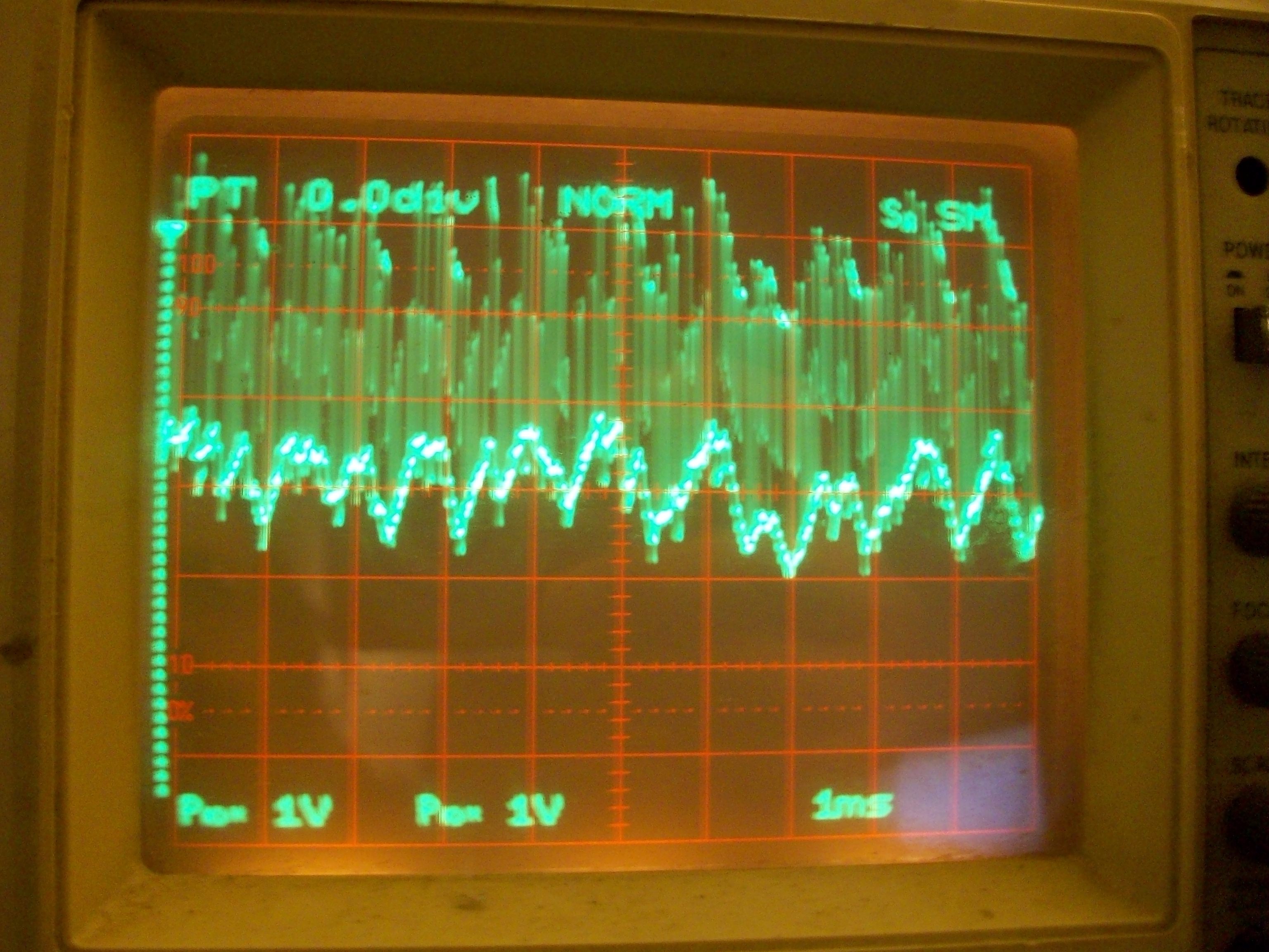
Here, the upper trace shows the output of the AC-coupling capacitor, before feeding into the diodes. You can see that the peaks and valleys vary in value from cycle to cycle, this variance is what determines the output voltage... A sort of dual-retriggerable peak detector circuit that relies heavily on the fact that the input voltage is always switching from 0V to 3.3V during each cycle.
Does it work *exactly* as I'd hoped...? Not sure, haven't done the full gamut of experiments yet. It definitely seems to work well with slowly-varying changes (as would an R/C filter, if I didn't need a negative output signal) (not shown here). Though, it looks like the output is scaled down a bit during these sudden-changes... something to ponder in later experiments.
-----------
Update:
Excellent results after swapping capacitors and changing some pots... *excellent*.
Video, maybe, soon.
Interesting side-effect I vaguely foresaw, but hadn't quite pinpointed... This circuit *inverts* the signal... E.G. 80% PWM is 3.3V for 80% of a cycle and 0V for 20%... So, an average of 80% of 3.3V, yet results in a *lower* voltage-output from the circuit... This would make sense... The average being .8*3.3 would be the "DC-offset" which is *removed* by the AC-coupling capacitor. The circuit output follows the *negative peak* of the AC-coupled signal, and since the DC offset increases with the PWM duty-cycle, and that DC-offset is *removed* by the AC-coupler, the negative peak goes *lower* as the PWM duty-cycle *increases*. Easily compensated-for in software, but an interesting side-effect.
Oddly, that's hard to see in the images above... The output voltage shown above seems in many cases to *follow* the positive duty-cycle. There's a lot at play in there... Of course we'll see *some* increase with the positive half of the duty-cycle (when the zener is on). The output of that circuit (with the old capacitor and pot values) was *way* off, 0.2V/div, while the 3.3V PWM signal varied dramatically in duty-cycle...
So, here's a snapshot of the *excellent* results with the new values:
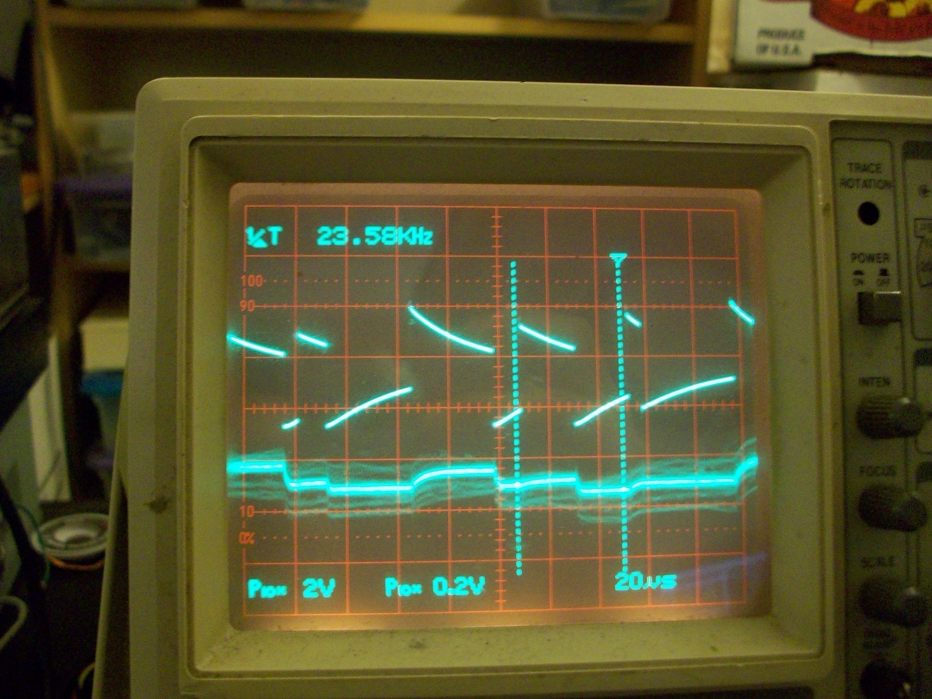
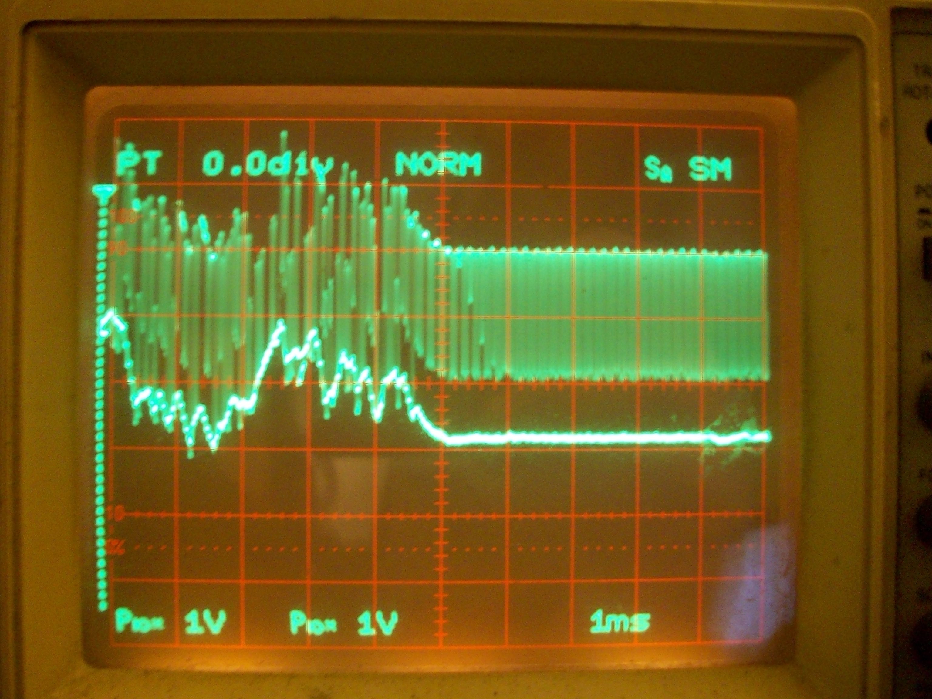
The upper trace being the PWM signal straight out of the microcontroller, the lower trace is the circuit's output. Note when the PWM duty-cycle is *low* for long-durations, the output voltage *increases*.
Here it is with the "top" trace after the AC coupling capacitor, and both signals centered with 0V at the center of the screen. Note how the output signal follows the bottom of the output, and goes both negative and positive. (Also note that it's about one diode-drop higher than the lower "peaks").
Again, the output signal is centered at 0V, so the signal swings from roughly -1V to +1V (again, without a negative power supply). And, *way more importantly* than its fast-response is that works great at constant PWM values.
E.G. the PWM in the above image is running at about 60%. (Obviously, due to the AC coupling, this fails when running at 0% and 100%.) The output of the circuit is a (roughly) constant *negative* 0.4V There is *slight* variance on the output as the diodes switch, a subtle triangular-wave on each PWM cycle, but I think that should be more than acceptable for driving a motor.
-----------
Update 2:
Ah hah... So there may be a distinct "R/C constant" going on here, still... making its output a bit more like a regular-ol' RC-filter than I expected... But not bad... and maybe adjustable and still functional...
Actually, not sure what I'm seeing, here... I think there's some aliasing to make things more confusing.
-
Groovy Circuit Explained...
01/23/2016 at 14:22 • 0 commentsHere's an explanation for the circuit in my last log...
First:If you haven't seen it yet, check out this groovy circuit I came up with!
0->3.3V PWM (20-80% duty cycle)
                V+
                ^
                |
                \
             R1 /
                \
                |  D2
                +--|>|----.
                |         |
                |       __|__| D3
                |      | / \   3.3V
                |       /___\  Zener
            C1  |  D1     |
0->3.3V >---||--+--|<|----+----->  >----.
                |         |             |
                \        === C2         \ Amp
             R2 /         |             / Input
                \         V             \ ~30k
                |        GND            |
                V                       V
               GND                     GND
OK, so I'm not 100% certain it does what I think it does... but it seems darn-close. Here's what I intended:
My audio-amp's input is biased at 0V... so a 0V input results in a 6V output. ~0.4V input results in 12V output. ~-0.4V results in a 0V output. Odd, yes... it is, in fact, a single-supply amplifier... Obviously, they were expecting AC-coupling.
This circuit serves several purposes. First: It converts PWM to a (roughly) linear voltage... kinda like an R/C filter / averaging-circuit. Second, and more importantly, it "shifts" that "average" down into a range for the input, such that e.g. 20% PWM Duty-Cycle results in -0.4V output to feed into the audio-amp's input so that its output will be 0V. Third, hopefully, the "linearizing" aspect is limited to a *single* PWM cycle, thus if the PWM duty-cycle changes dramatically suddenly, this should respond to that quickly, rather'n slowly rising to the change like would happen with an R/C filter.
Starting with the AC-Coupling capacitor C1...
0->3.3V >---||------>  >----.
            C1              |
                            \ Amp
                            / Input
                            \ ~30k
                            |
                            V
                           GND
Feeding a high-enough-frequency PWM signal through the AC-coupling-capacitor results in basically the same waveform fed into the amp-input, except shifted to be "centered" around GND...
At 50% duty-cycle, it's perfectly centered...
50% duty-cycle AC-coupled:

3.3V .-----.     .---    +1.65V  .-----.     .---
     |     |     |               |     |     |
     |     |     |   -->  0V - - | - - | - - | - -
     |     |     |               |     |     |
0V   '     '-----'       -1.65V  '     '-----'
As the duty-cycle is varied, the DC-component of the input-signal varies, but that DC-component is removed by the AC-coupling capacitor C1. The result is that the *peaks* (both negative and positive) of the waveform shift up and down. The *average* is kept at 0V, so then, basically, the *area* of the upper portion of the waveform and the area of the lower portion of the waveform are kept equal...~10% duty-cycle AC-coupled: 3.3V .--. .--. 2.9V .--. .--. | | | |A1| A2 | | | | --> | | | | | | | 0V - | -|- -v- - | - - 0V ' '--------' -0.4 V ' '--------'So, A1 ==A2, the waveform shifts up, but its amplitude is unchanged, 3.3V.Well, this alone is fine for my motor-driving-purposes... -0.4V is still low enough to cause a 0V output during the low portions of the PWM cycle. And the amp's input seems perfectly OK with 2.9V, which is >>0.4V input necessary to output 12V. So, we have, roughly, PWM on the audio-amp's output, to drive the motor. Awesome.
Except, this audio-amp has a very slow slew-rate for my needs... A square 50% duty-cycle input at my 32kHz PWM frequency results in an almost perfectly triangular output.
That's fine, I was kinda interested in experimenting with *linear* voltage control of the motor, rather'n PWM, in the first place... So, now how do I linearize my microcontroller's PWM output...? Typically, an R/C filter, right...? Except, I need its output to go *negative* from a 0-3.3V rectangular-wave... hmm... And I don't have a negative voltage-supply to feed into a voltage-divider, or whatnot... And, de-facto, If I find the *average* of the AC-coupled signal, it'll always be 0V.
Also, it'd be ideal if the "averaging"/linearization circuit doesn't introduce any noticeable delay... E.G. if the PWM signal changes from 50% to 80% in a single cycle, it'd be awesome if that change is fed to the motor almost immediately, rather than slowly rising, as an "averager" would do... (This part is the part I'm not certain my circuit accomplishes...)
OK, so the output of the AC-coupled signal has portion of the PWM cycle that *goes negative*... and somehow I'd like to "average" *that negative value* and not the *entire* value...
So, then I thought: a peak-detector:
0->3.3V >---||-----|<|----+----->  >----.
            C1     D1     |             |
                         === C2         \ Amp
                          |             / Input
                          V             \ ~30k
                         GND            |
                                        V
                                       GND
Now, that signal drawn before is fed into the diode and C2 such that... if the voltage on C2 is greater than the signal (which goes down to -1.65V in the 50% duty-cycle case), the voltage on C2 will drop down to (roughly) the input-value of -1.65V. Excellent.If C2 is large enough, it will maintain that value throughout the whole PWM cycle... So, its value will be (roughly) a constant -1.65V. Awesome, right...?
So, the output of the negative-peak-detector circuit above is always negative, since it's detecting negative peaks. I figured, why not feed that guy's output into a voltage-divider to pull its, say, ~-3V to ~0V output up to something more like -1V to +1V...
                          V+
                          ^
                          |
                          \
                          /<------------.
                          \             |
                          |             |
0->3.3V >---||-----|<|----+             |
            C1     D1     |             |
                         === C2         \ Amp
                          |             / Input
                          V             \ ~30k
                         GND            |
                                        V
                                       GND
But, now there's
more loading on that capacitor... I've got to think about R/C
constants a bit more, etc... I dunno exactly, it just didn't quite
sit right with me, and I didn't even bother building it... At some
point it occurred to me, wait, I could bias *before* the diode! Then
any loading caused by the biasing-circuit would be handled by the the
signal's *source* rather than by my detector-circuit, right...?
V+ ^ | / Bias somewhere \ / 'round 1.65V-0.4V...? R1 / / \ / C1 | / D1 0->3.3V >---||--+--|<|----+-----> >----. | | | \ === C2 \ Amp R2 / | / Input \ V \ ~30k | GND | V V GND GNDFAIL!And not because of my hokey estimation of the bias-point. That's easily adjusted into reason with an input-signal, 'scope, and using a potentiometer for R1 and R2. Just adjust the potentiometer (R1 and R2) so a 50% duty-cycle input results in a 0V output at C2.
No, the problem is the diode is never *on* when the lower portion of the PWM cycle is *positive* (after the AC-coupling capacitor). Which, of course, it intentionally does now when the duty-cycle is above 50%... So it's basically a negative-voltage-only-peak-detector, completely destroying the purpose of the biasing in the first place...
So, then, a pull-up resistor at C2... right? Duh... same problem as the biasing on C2, have to think about those R/C constants and whatnot... How many PWM cycles would it take to rise to a change in Duty-Cycle...?
And what when C2 has too large a value, and the PWM duty-cycle decreases to 10%? The "negative peak" is now -0.4V, much higher than -1.65V on the capacitor... The diode remains "switched off" and the capacitor's only means of reaching that -0.4V is to deplete its charge through the audio-amp's input... This takes some time. The microcontroller is telling that motor to stop ASAP, but it's not stopping until that capacitor depletes!
I tried a few things, came up with a few ideas, but nothing really seemed to do the job. Kinda gave up on the idea of accomplishing the task of a *linear* output for the motor... At least, without a negative voltage supply. Maybe I should just stick with PWM *output* and lower that PWM frequency so the triangular edges are roughly unnoticeable (which would *definitely* be within the audible range).
A bit later it occurred to me... The PWM signal coming out of the microcontroller (as well as that on the output of the AC-coupling capacitor) always maintains a constant amplitude... 3.3V. When the duty-cycle decreases, in the case described earlier, the *positive* peak voltage, on the output of the AC-coupler, increases as well. Hmmm... maybe I can use that increasing *positive* peak to pull up the *negative* peak-detector. Thus the introduction of D2 and D3...
                   D2
                .--|>|----.
                |         |
                |       __|__| D3
                |      | / \   3.3V
                |       /___\  Zener
            C1  |  D1     |
0->3.3V >---||--+--|<|----+----->  >----.
                          |             |
                         === C2         \ Amp
                          |             / Input
                          V             \ ~30k
                         GND            |
                                        V
                                       GND
The idea, again, being that when the *positive* peak voltage (after C1) increases, it will pull up the voltage on the negative peak detector's C2. In hopes, then, that the "linearized" output will respond almost immediately to changes in the input PWM signal.
And... with this arrangement, those biasing resistors *can* be placed before D1/D2, which hopefully results in their having negligible effect on the charge/voltage stored on C2, so plausibly C2's value needn't really be calculated, just throw in a value and let the source provide the extra current necessary by the loading of the bias resistors.
Now, here's where I'm not *certain* it does *exactly* what I planned, increasing C2 to a really large value does seem to delay changes... so I guess I just lucked-out that the random values I chose seemed to do the job quite well.
So, for the past week or so, I've been working on a new circuit for my PWM source... This guy will handle up to 5 separate axes (the audio-amp chip can handle four). But the key-factor, for now, is that it will have easily-adjustable settings for experimenting with different motor-driver chips/techniques. E.G., with this system we've got to use locked-antiphase (there's only one input). And, since it's AC-coupled, the PWM value should never be allowed to reach 100% or 0%, or the output from the AC-coupling capacitor will go to 0. A few other settings would be handy to experiment with, as well.
So we have the display for adjusting settings, to the right of that is my microcontroller, the breadboard has the "peak detector" circuit. The red board between the breadboard and the 'scope is the audio-amp. The scope is showing the output of the AC-coupling capacitor and the output of the circuit.![]()
This was the first chance I've had to connect the motor since it'd been waiting on this new microcontroller-circuit. With the brief testing I've done so far, the system (the "groovy circuit" in particular) seems to meet my goals darn-near perfectly. Yeah, it's not perfect, but it's doing the job.
-
Check out this groovy circuit!
01/12/2016 at 08:11 • 4 commentsCheck out this groovy circuit I came up with!
0->3.3V PWM (20-80% duty cycle) V+ ^ | \ R1 / \ | +--|>|----. | | | __|__| | | / \ 3.3V | /___\ Zener | | 0->3.3V >---||--+--|<|----+-----> >----. | | | \ === \ Amp R2 / | / Input \ V \ ~30k | GND | V V GND GND -
Audio Amp Motor Driver - New Chip, surprising biasing + Linear Thoughts
01/12/2016 at 06:28 • 0 comments2022-02-05: Heh, stumbled on this old draft from 6 years(?!) ago....
Soldered up the new chip: TA8251AH. This guy could potentially drive *4* motors.
In a sense, its interface is a lot more like a typical motor-driver than the last chip, TDA1510, which has a typical op-amp (or comparator) style interface.
By which I mean... each "channel" on the TA8251 has *one* input and *two* complimentary outputs...The TDA1510, on the other hand, essentially had two separate op-amps, each with inverting and noninverting inputs... so to drive a single motor, 4 inputs had to be taken into account (again, as opposed to *one* on the TA8251).
(Both chips are single-supply; ground and V+, no V-. I'm using 12V)
For the TDA1510, this meant I could treat its inputs (somewhat) like a comparator... To drive it with a PWM signal from a microcontroller, I managed to use some simple voltage-dividers to bump the 0-3.3V PWM signal up to something more like 5.5V to 6.5V, and bias its other terminal to 6V... (explained in the last log). So, when the PWM signal is 0V, the non-inverting input is ~5.5V, this is less than 6V, so the output of the "comparator" is low... Similar for the other case: 3.3V -> ~6.5V > 6V -> output high.
I kinda figured, since the TA8251 only has one input (presumably the 'non-inverting' input, while the 'inverting' input is internally biased).... that the bias-point would be around 1/2 V+, or 6V in this case...
Interestingly, the TA8251's input is biased at 0V! That means 0V at its input results in 6V at both its outputs. About 0.4V at its input results in 12V at the positive output and 0V at the negative output. But, then... how do I get 12V at the negative output and 0V at the positive, to reverse the direction of the motor (or handle the negative half of a sine-wave, if it's driving a speaker, like normal)? Despite being a single-supply chip, it requires ~-0.4V to swap the output polarity!
OK, so that's an interesting bit to consider... how'm I gonna get a 0->3.3V microcontroller signal to go *negative* without a second power-supply...? LOTS of ideas been runnin' up through this head... including creating a negative supply with a 74HC04(?) oscillator, capacitor(s), and diode(s), then using a similar "voltage-divider" scheme as with the TDA1510, except in reverse... Seems doable, but that voltage-divider scheme actually uses quite a bit of current, especially since the input-resistance of this chip is spec'd at 30kohms... might be hard to keep that negative voltage steady, with such a large load.
Then there's the other thing... This guy switches *much* more slowly than the TDA1510. In fact, the TDA1510 was having little difficulty keeping up with ~32kHz PWM, and its sharp edges, despite being *way* outside the audio-range. This guy, OTOH, is *just barely* switching from one rail to the other with 32kHz PWM at 50% duty-cycle. Fine, that's expectable, if someone drove a 20kHz signal at rail-to-rail on a 30W speaker-system, they'd probably be excruciatingly uncomfortable... and that'd be a sine-wave, not a square with all its higher harmonics... So, this thing probably works fine for audio, even at extremes. But it's a little less ideal for motor-driving.
So, a running-thought has been to possibly experiment with driving the motor with a *linear* voltage, through these inherently *linear* audio-amps... Some ponderings: Would they produce *more* or *less* heat this way than essentially switching from rail to rail? Note that most actual motor-drivers work with the transistors in *saturation* off or on... for BJT-based systems this means emitters are typically tied to the rails. In an audio-amp, however, it seems the typical method is to use the emitters tied to the *load*... can they saturate in this configuration? Several other thoughts along those lines...
Another thought: Without *switching* (using a linear voltage, instead), combined with the feedback-loops used in op-amp amplifier circuits (does this chip have an internal feedback loop...? hmmm)... it might be plausible to not need freewheeling/flyback diodes... I haven't quite wrapped my head around this one, but it's something to ponder. Am-Thinkink, the feedback loop should take care of noticing that the output voltage is higher or lower than expected, and compensate accordingly... right?
(And would this linearization affect the motor's positional-controllability...?)
Anyways... Regardless of whether I choose to go the linear-route, I still have to figure out how to supply a negative input voltage from my positive PWM signal. I can average it, of course, using a resistor and capacitor, to come up with a linear output voltage to feed into the amplifier, but it'd still be 0->3.3V.
For PWM values not near 0% and 100% duty-cycle, I can AC-Couple it... And that actually works pretty well. Also, this chip appears to *actually* output rail-to-rail, so losing a few % of the duty-cycle-range is roughly the same as the loss in power-output-range from the other chip which clipped at a couple volts lower than the upper rail... (~10V).
That's the easy solution... 50% duty-cycle = stop, "full-forward" is something like 80%, full-reverse is something like 20%... Just configure the software so the minimum and maximum PWM duty-cycles assure that the 3.3V signal still exceeds -0.4V and 0.4V on the other side of the AC-coupling capacitor... No prob... Again, the motor itself will never see the full power capable of being supplied by the rails, nor the amplifier-chip, but that seems to be a functional solution... 80% of 12V isn't enough for yah...? Use 18V.
Alright.
Then I got fixated on trying to figure out how to squeeze that extra 20% out of it, or something... and... wound up back to linear..
Actually, was it that I wanted that extra 20% or that I wanted to figure out a way to drive it linear with the negative-input requirement...?
Anyways.
I had the brilliant idea... what about a "peak detector", which would maintain the value of the negative peaks coming out of the AC-coupler...? Feed that into a capacitor, and the output should always be the lowest-value... Then voltage-divide/calibrate that back up so that 50% PWM results in 0V to the input... Brilliant, right...? Except, of course, feeding this into a capacitor to "maintain" the negative peaks means that when the PWM value increases (to attempt to reposition the motor), the negative peak from before will still be stored... brilliant fail. And so many more fails in that line-of-thought that I can't quite recall at the moment. Lots of consideration of time-constants and load resistances that I hadn't really pondered... and more.
Oh yeah, another brilliant fail on this front... well, lemme show you the circuit...
0->3.3V PWM (20-80% duty cycle)
                V+
                ^
                |
                \    Bias around
                /   / 3.3V / 2 + 0.4V ?
                \  /           - ?
                | /
0->3.3V >---||--+--|<|----+----->  >----.
                |         |             |
                \        ===            \ Amp
                /         |             / Input
                \         V             \ ~30k
                |        GND            |
                V                       V
               GND                     GND
OK, great, right...? The idea being to do the "calibration" on the *supply* side, rather than the *load* side (where R/C constants would be a bigger concern). But the "negative peak" detector *never goes positive*. Duh.
So, realistically, there needs to be some sort of "pull-up" resistor on the capacitor-side of the diode, and then R/C becomes a big concern, and all the other factors of peak-detection (and over-maintaining) and whatnot came to mind...
Was about to call it quits, but then it came to me... I don't want it *always* pulled-up... I want it pulled-up whenever the input-signal *goes* up... The input to the peak-detector being a rectangle-wave with a constant magnitude (3.3V), which varies in *offset* (as a result of varying duty-cycles)... I want increasing positive peaks to pull up the negative-peak-detector...
this came to me...
0->3.3V PWM (20-80% duty cycle)
                V+
                ^
                |
                \
             R1 /
                \
                |
                +--|>|----.
                |         |
                |       __|__|
                |      | / \   3.3V
                |       /___\  Zener
                |         |
0->3.3V >---||--+--|<|----+----->  >----.
                |         |             |
                \        ===            \ Amp
             R2 /         |             / Input
                \         V             \ ~30k
                |        GND            |
                V                       V
               GND                     GND
Check it out! When the positive peaks increase, the detector is pulled up, when the negative peaks decrease, the detector goes *negative*. The capacitor... well, shoot, now what does that do...?
The whole thing's not an *average* but it kinda takes the average *of a single cycle*, and is relatively immune to the load resistance... R1 and R2 can be a potentiometer for calibrating the offset-voltage
-
Audio Amp Motor Driver -- GO!
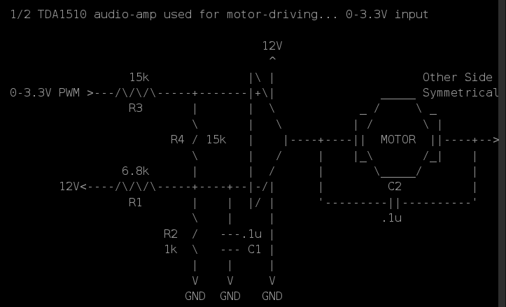
01/02/2016 at 07:29 • 0 commentsAlright, so the basic idea is to treat the (linear) audio-amp (TDA1510, so far..) like an op-amp, then to treat that op-amp as a comparator, then feed that comparator a PWM input. This [mis]treatment might be questionable, but it seems to work!
This log is a combination of a draft I didn't publish during the testing-process, and my most-recent results.
Previously:
Currently I'm driving my audio-amp with a 12V-on 0V-off PWM source (from another motor-driver). So, this means a lot of voltage-dividers. BUT: It also means that it's easy [easier?] to bias this input-voltage somewhere 'round half the supply-voltage (this is a single-supply amplifier).
After TONS of experimenting: Here's a circuit that seems to work *great*:
![]()
The input is driven by a 0V=Off 12V=On source. Forward is handled by driving the 'left' input with PWM and the 'right' input with 12V. Reverse is... the reverse of that.
C2 is necessary due to oscillation. I can't quite wrap my head around this, but without it we get this: Well, shoot, I didn't take a photo...
          _____       _____
      12V|     |     |     |
In:    0V|     |_____|     |_____

    ~12V |     |     |     |
         |||||||     |||||||
Out: ~0V |     |_____|     |_____
Something like that, anyhow. I don't get it. But the capacitor (C2) *definitely* fixes that, in this case anyhow.R1 and R2 form a voltage divider biasing the inverting input of the 'comparator' at 1/2 Vsource = 6V. The capacitor, C1, just serves to try to filter out noise.
R3 and R4 values are large enough that we can (allegedly) pretend that they don't affect the output of R1 and R2... So, then, we have a voltage-divider which divides the input-voltage in half in each direction, WRT 6V. So, 0V at the input results in roughly 3V at the non-inverting input. 12V at the input results in roughly 9V at the non-inverting input. 3V is lower than the inverting-input's 6V, and we're treating the [poor] thing as a comparator, so the output hits the ground-rail. 9V is greater than 6V, so the output hits the V+ rail (as best it can).
Great! And confirms my theory that we can treat this audio-amp as an op-amp as a comparator...
(Note: In the interest of reducing part-count, I actually tie *both* "comparators'" inverting-inputs, and both circuits' 'R4' to the *same* voltage-divider (R1, R2, C1). In *this particular* circuit, it seems to work fine).
Note, *tons* of experimenting was done before coming to this circuit... Lots of "ideal op-amp" assumptions that just didn't seem to work-out... In fact, in some cases I'm almost certain I saw some large (milli-amps) current flowing between the inverting and non-inverting "inputs" despite their alleged 1Mohm input-impedance. So... again, I'm no analog-expert. The above circuit seems obvious... now.
Oh, important-note... don't allow the input voltage to *exceed* either of the power-rails. This was a kicker, I think... When the motor's on, the voltage to the amp's power pins was sagging nearly two volts. The input voltage, though, was still 0-12V. This, as I recall, resulted in some really odd behavior, like "latch-up" (?) where some PWM cycles would actually *stick* at the upper rail despite the input signal going low. Weird.
--------------------
Here's another circuit... again, the first came from *lots* of experimenting. Sure, it makes sense and mightas well be the *first* one I tried, but it wasn't. E.G. Why not just remove R4 altogether...? Or maybe tie it to ground, instead...? What about *really high* value resistors...? E.G. 100k? Yeah, all that seemed to be nogo. And some *really* weird effects from doing-so.I didn't document them all, but here's another circuit... The idea being: the microcontroller I intend to use runs at 3.3V, so its output will be ~0V or ~3.3V. In the interest of using my current setup to test before actually building my end-circuit... The first step was to divide my current setup's 0-12V PWM output down to roughly 0-3.3V... That's simple with a voltage divider... I used the general-purpose assumption that as long as its resistors are at least 10x the output/load resistance, then we can "pretend" the output-resistance has no effect... So, the 0-12V PWM signal is fed into a 3.3k resistor, and that resistor is pulled to ground with a 1k. 'scoping the output of the voltage-divider looks alright, so I think the "pretending" was reasonable enough...
Now, again, we're [mis]treating this poor audio-amp as a comparator, so I figured why not bias its inverting-input at something like 3.3V/2=1.65V... Then use, basically, the same circuit as above...?
![]()
Looks alright, right...?
The result, as I recall, was basically an always-high output... at the upper-rail. Weird... no? I think this has something to do with the CMRR, which always seems to bite me in the a** whenever I do op-amp circuits.So, no, it's not a comparator. Better to bias that thing somewhere 'round 1/2VCC and use small signals around there.
---------------
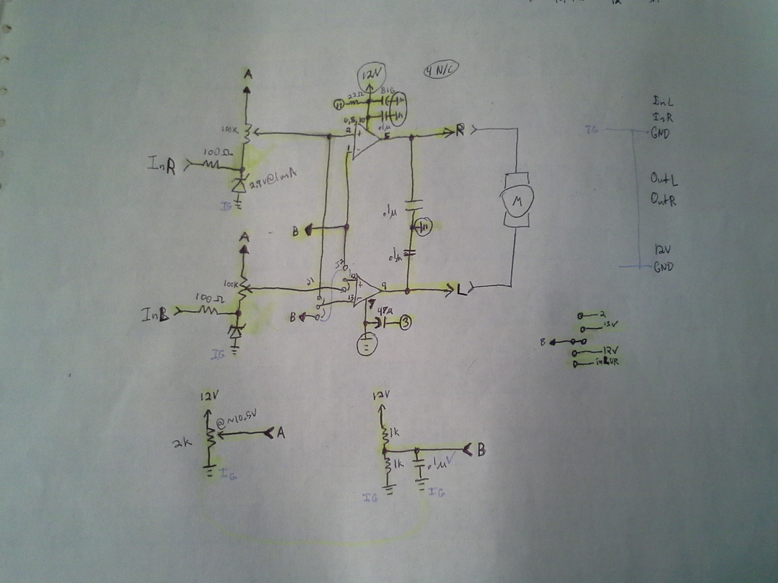
Here's the final (probably) microcontroller-output-friendly version of the circuit (which is now built on a PCB and has been tested with the 0-12V -> 0-3.3V voltage divider explained earlier).
![]()
A few things: The zener-diodes (and 100ohm resistors) prevent current from flowing *into* the microcontroller-output when the output is high. It may not be necessary (in fact, the PIC32 electrical-specs actually list the amount of current that can safely flow into the output when it's high... weird spec...? I'm almost certain I've never seen it on other uCs). My thought was that the 100k resistance between ~10.5V and the 3.3V microcontroller output would be similar to tying a load between two positive voltage regulators... they're not meant for regulation of negative-currents, so the lower-voltage regulator will rise to the higher-voltage. So, maybe, the microcontroller's output pins are similar...? Actually, *that* seems kinda absurd, now... but not so absurd is the plausibility that my microcontroller *might be running off a positive voltage regulator*. Also, the uC pins have protection-diodes, which probably would limit the voltage to something like 3.5V. Anyways, the zeners may not be necessary, but it made sense to me at the time. My original plan was to just use another resistor to ground, but then it occurred to me I might bump up the voltage on the motor-driver "amp", and then the voltage across that resistor would increase...
Also an interesting and beneficial discovery: The Zener Voltage is rated *at some expected current*... Check those I-V plots (and run experiments)! I've a ton of 3.9V Zener Diodes, and it turns out that at 1mA they're only 2.9V! That's a HUGE difference! And beneficial for my 3.3V circuitry.
Anyways, as far as the circuit's concerned, it's getting *roughly* 0V and 3V input to the bottom of that 100k potentiometer. I don't recall how, off-hand, but somehow I determined that 10.3V into a voltage-divider that had either 0V or 3.3V at its bottom terminal would give me an output-voltage slightly below or slightly above 1/2 V+ = 6V. (I wanted to bias the inverting input to 1/2VCC to limit the common-mode voltage, as well as to design this circuit closer to the one that will be used with my new audio-amps which *don't have an inverting input*). OK, so I need a 10.3V source, thus another voltage-divider.
End-Result: adjust the 2k pot to output something around 10.3V, then adjust the 100k pots while PWM is being input such that the output toggles above and below 6V.
Seems to work great. Surprising, kinda, judging by how much difficulty I had getting the thing working at all in the first place... now it seems almost like an ideal op-amp or even comparator circuit.
The jumpers allow for Locked-Antiphase or DIR/PWM input. My current setup drives one output high and PWMs the other, then swaps those for the other direction. But the new audio-amp uses only *one* input for *both* its outputs (one is inverted). So that will require locked-antiphase (where 50% PWM results in no motion). So those jumpers allowed me to test that before I had the new chips.
Alright, enough talk...
First: DEFINITELY put a heatsink on it. A good one. I might've gone overboard, but it doesn't even get hand-warm now, and before it was so hot I could smell it and dropped-out (due to the thermal-protection circuitry?) quite a bit. (TODO: This might be the problem with the Class-D amp... maybe that heatsink was too small...?)
Here's the end-product *almost* complete:
And here is a screenshot from the not-yet-editted video of the system functioning:
![]()
NOTE: So far "freewheeling"/"flyback" diodes *HAVE* been deemed necessary... They're not shown in the schematic but have been attached off-board via the terminal-block.
My original thought was that since the outputs of a linear amp are push-pull, the amp *might* be capable of *preventing* freewheeling voltage-spikes.
This logic... plausible, still, I think. But *most likely* would require feedback, treating the amplifier as an op-amp rather than as a comparator. Worth exploring, but might have some other consequences... The biasing would have to be *just right*, and I think the gain would have to, as well. The actual output might have to be reduced such that it doesn't *quite* reach the rails...? I'm not sure. If that's all the case, then four diodes per motor is minimal in comparison...
As it stands, this is darn-near, if not fully-functional as a motor-driver. It's a few extra components, but not bad. A bit of calibration may be necessary when using a different supply-voltage (could that be avoided?) Definitely warmer than, say, the LMD18200 I've used for some time, but a heatsink seems to handle that fine. Switching-speeds...? I think I'm running something like 31kHz, right now (way above audible range) and it seems to be handling it fine.
------------------
Coming up next....
Video!
And Later....
![]()
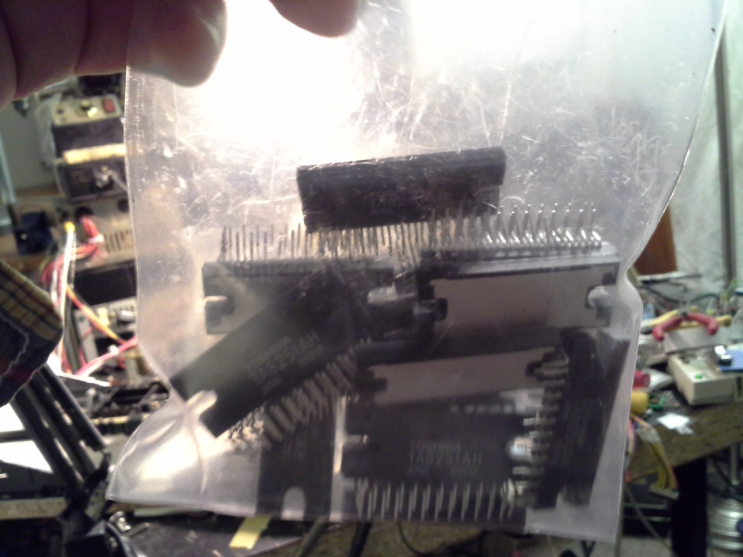
Each of these audio-amp chips could plausibly control *4* DC motors, or two bipolar steppers! With sale-prices I got this entire bag for $5! Or one could look at it as though I placed an order for much-needed rotary-tool bits and got drivers for 56 motors for $2 :)
Random Ridiculosities and Experiments
Sometimes yah's just gots tah try somethin', regardless of whether it'll become a full-fledged "project"...
 Eric Hertz