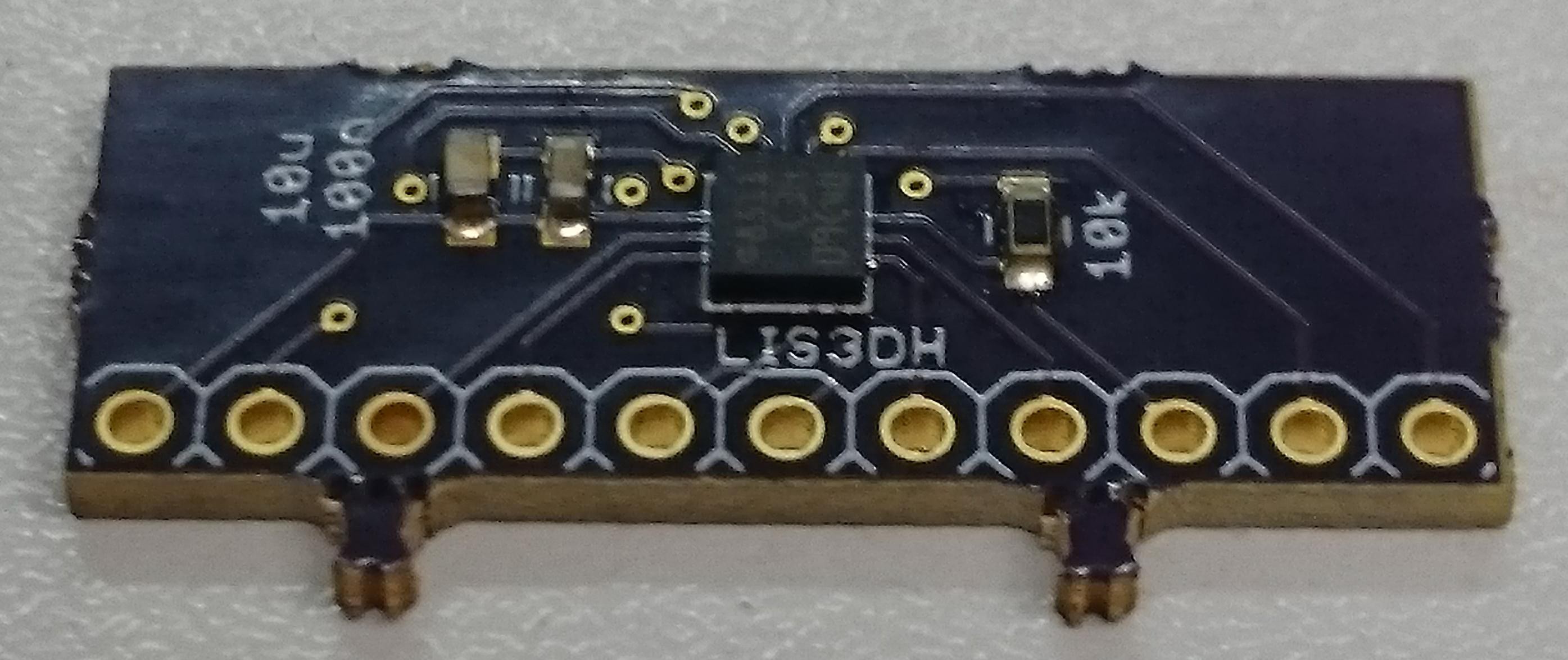
LIS3DH breakout board
3D accelerometer with SPI, I2C and 3 ADC inputs
3D accelerometer with SPI, I2C and 3 ADC inputs
To make the experience fit your profile, pick a username and tell us what interests you.
We found and based on your interests.
Finally I have a good board:
After seeking for advice in a few places, this is how I soldered the LGA package:
My explanation for why this works is quite simple: with the solder applied with an iron (just drag it across the pads), each pad will receive about the same amount of solder. This is almost impossible with paste applied manually. Having equal amounts of solder on the pads is good because each resulting joint will have the same height. With paste I had the impression that joints with a larger amount of paste tend to push the part further up than the neighbouring joint can "stretch", thus causing joints with no contact at all. Also, two adjacent pads with a large amount of paste can easily cause a short.
I tested the board with adafruit's LIS3DH library, which worked very well.
After re-soldering two boards on a hot plate I got one working in I2C mode. The SA0 pin is not soldered correctly, but the internal pull-up is doing its job so I can communicate with the chip at address 0b0011001:
So far this has been the hardest chip I ever had to solder. If you don't
need to mount this on a custom PCB, go for a ready-made breakout board
(this advice might change, or not, when I tested the new layout).
I wrote test code for both I2C and SPI mode, without luck. The adafruit library also can't communicate with the chip, so I guess I damaged it during soldering. I double-checked the eagle part library, the schematic and the layout and all seem to be good.
All three boards are used now so I redesigned the land pattern a bit and sent another order to OSHPark. The pads I had before seemed to be a bit too wide, so I narrowed them and extended them to the outside. The silk screen had to move to make space for the extended pads, so I just left the corners and a minimal pin 1 indicator.
Here's a comparison:
The modified pad geometry should help against solder bridges when soldering in an oven, when I can't poke the chip while the solder is liquid.
After the new (now correct) boards from OSH Park arrived I could start trying to solder the parts. 0603 passives are no problem at all, but the LGA-16 is. It's really tiny, and the pads on my board seem to be too wide, resulting in shorts between two pins on two boards:
I did my best to apply only little solder paste, equal amounts to each pad, using a kapton tape stencil:
So I asked for advice on electronics stackexchange, and the most important hint was to use a way of reflowing that allows me to poke the chip while the solder is liquid. Having no hot air gun I decided to use a hot plate. I've added my solution as an answer there, including all the details.
This time everything worked and I have a board without shorts and all pins seem to be connected:

Now I just need to find some time to write test code!
I thought I had solder mask openings, but they aren't there:
Bottom looks ok though:
I Guess I'll have to wait another two weeks before I can solder this!
I contacted OSHPark about this and they'll send me new boards with swift service and faster shipping. That's awsome!
Create an account to leave a comment. Already have an account? Log In.
Become a member to follow this project and never miss any updates
By using our website and services, you expressly agree to the placement of our performance, functionality, and advertising cookies. Learn More
impressive project!