Close
0%
0%

1-Cell MCU

Run a low-power MCU efficiently from an AA(A) or button cell

Similar projects worth following
Microchip markets the MCP1624 boost converter as a solution for powering PIC MCUs in single-cell applications. The downside of this part is the 60uA or more quiescent current (measured at Vin). By using a GPIO line to strategically shut down the converter, the quiescent current can be reduced dramatically, allowing for efficient MCU sleep and longer battery life.

This project is really all about a resistor.  Specifically, the 1.5M resistor, R3, in the schematic below.
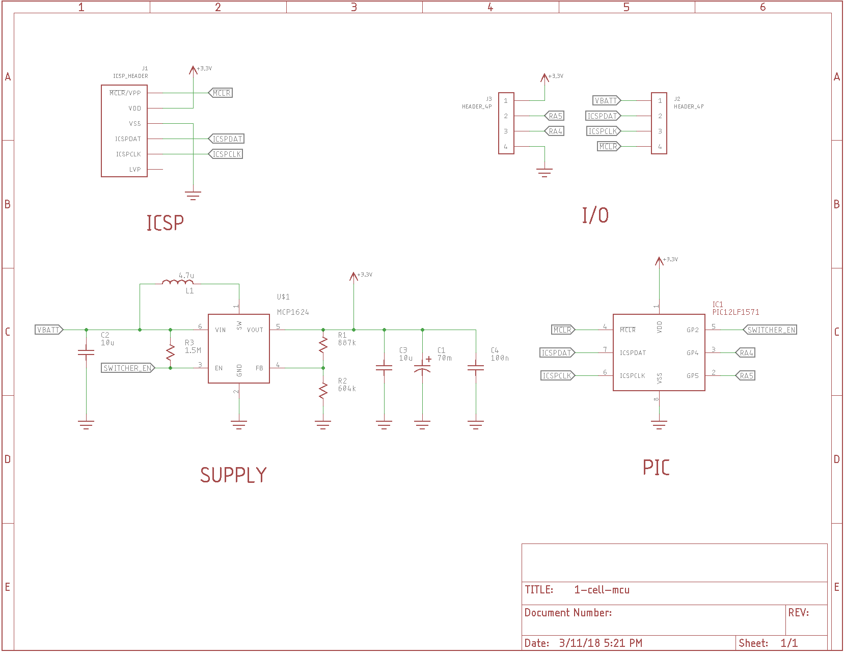
The MCP1624 is a DC-DC converter that will start at voltages as low as 0.65V (typ), so is ideal for running a PIC or other MCU from a single AA(A) cell or similar 1.5V nominal source (even button cells).  But, it's not exactly nano-power.  The graphs in the datasheet show a 100uA quiescent input current drain for a 1.1V source and 3.3V output, and it gets worse as the battery voltage falls.  The goal of this project is to bring this current down.

The idea is that the PIC can shut down the converter during sleep or periodically when running to minimize the current consumption.  I'll admit, having the PIC shut off its own power supply sounds like a recipe for disaster.

That's where R3 comes in.

When power is first applied, the PIC GPIOs are tri-stated, so R3 turns on the MCP1624 by pulling the enable input high.  The MCP1624 comes on and charges C1, a 70mF supercapacitor, to 3.0V (selected with R1 and R2).  When the PIC needs to sleep for a while, it can disable the MCP1624 by setting RA2 to an output and pulling it low.  At this point, the PIC is running from the energy stored in the supercapacitor.  This particular PIC has a low-power brownout reset (LPBOR), which will monitor the supply voltage and reset the PIC when the supply drops to a predetermined level.  Should the PIC not wake up in time to re-enable the supply, the LPBOR will reset the PIC, which returns the GPIO pins to tri-state, starting the DC-DC converter again.

I expect that the normal mode of operation will be to set the sleep time so that this never happens, and the capacitor gets fully recharged periodically without the PIC resetting.  But, the safety net is there just in case.

I'm grossly violating the 100uF maximum output capacitance spec for the MCP1624 with C1.  I am hoping to get away with it due to the large ESR (100+ Ohms) of the selected supercapacitor.  This 100-ohm ESR doesn't matter when the PIC is in sleep, consuming a few uA maximum, but hopefully is enough to keep the MC1624 stable.  Now that I think of it, I should have added a site for an additional series resistor for C1 in case it's needed.

The leakage current for the supercapacitor also isn't specified.  This could easily dominate the current drain.  Plan B is to find some other large-ish, low-leakage capacitor(s).

I don't know yet exactly how low the sleep current will be, but I'm shooting for less than 5 uA.

I have some test PCBs ordered from OSH Park, and now just have to wait :(

The initial design is in the githubs.  I tested it: it works!

  • Better part, but very small

    Ted Yapo03/13/2018 at 20:21 0 comments

    So, I found the TPS61099x series of boost converters, which claim 1uA quiescent current and 75% efficiency at 10uA load.  These look usable out-of-the-box for micropower 1-cell MCU applications.  I do wonder, though, if the same shutdown trick can be used to reduce the sleep current even more by running the converter at higher current (and higher efficiency) to periodically charge some low-leakage storage caps.  I'm going to order a few and test them out.

    The downside I can see to this part is that the only package option stocked at DigiKey is a 1.23 x 0.88 mm BGA.  That's pretty small to assemble at home.

    Another small PCB from OSH Park coming up.  At least I'm batching them now, so they don't have to send me an envelope for $1 worth of boards :-)

View project log

Enjoy this project?

Share

Discussions

K.C. Lee wrote 05/01/2018 at 20:11 point

One thing to watch out for is the MCP1624 uses PFM at low power.  The low switching frequency can mess up analog/audio circuit.  MCP1263 would be better for those circuit as it has fixed frequency, but at the expense of lower efficiency.  The high PWM frequency is easy to filter.

I learnt this lesson the hard way in my visual impair project a few years back.

  Are you sure? yes | no

Ted Yapo wrote 05/01/2018 at 20:47 point

I saw the two versions in the datasheet.  That's a good tip - I chose th 1624 just based on the efficiency at low currents.

Analog circuits might have a problem with the wide range of supply voltages they'd might see with this kind of supply, too.

  Are you sure? yes | no

bobricius wrote 05/01/2018 at 19:08 point

I am try solve this problem on my supercapacitor watch without success almost all stored energy in stanby is consumed with step up converter. I think some time about attiny43u. I make one board with max1724 which have 1,5uA qc but your idea is very effective.

  Are you sure? yes | no

jaromir.sukuba wrote 05/01/2018 at 18:16 point

This is interesting project. Just by coincidence, I made research about single cell MCUs. My idea was to make particular device that can run of single Ag cell, but eventually I gave up.

I haven't found that much. There are offerings from Microchip and Silabs, with internal step-up circuitry (add inductor and there you go); both with not that much inspiring parameters. Both being 8-bitters, no 32-bit offerings; also both manufacturers do have just a few models, with not much of scalability. There is MSP430L092 that runs "natively" from single cell, but has no internal FLASH, you have to add external one via SPI. Sounds acceptable, but good luck finding anything (FLASH, EEPROM, SPI RAM) that runs from single cell, so TI's recommendation is to make bitbanged step-up to power the FLASH. A bit of meh solution.

Also, I found out there are next to none user output devices. Finding 1,5V LCD is hard, LEDs do not work much here and filament lightbulbs may work, but do not make much sense here.


On the other hand, for decades I'm surrounded by cheap electronics that run for ages on single LR44 or similar cell. Calculators, alarm clocks, thermometers, you name it. Brainbox is hidden under drop of black snot on PCB, with no apparent inductors, so it runs "natively" on 1,5V, including program storage. Is ROM key here?

  Are you sure? yes | no

Ted Yapo wrote 05/01/2018 at 20:45 point

The core voltage on modern CPUs is in the single-cell range, down to 1.2 or so for slow clocks.  Plus all the simpler devices you mention.  I doubt it's a technical issue, really. You can buy modern, fast logic gates (e.g. 74AXP) that work down to 0.7V:

https://www.digikey.com/product-detail/en/nexperia-usa-inc/74AXP1G08GMH/1727-1837-2-ND/4843077

I think it's a market problem.  Li batteries are everywhere, and compared with these, most primary cells are expensive and huge on a per-Coulomb basis.  Add in the lack of available displays, and maybe a low-voltage MCU just doesn't make sense.

  Are you sure? yes | no

jaromir.sukuba wrote 05/01/2018 at 21:45 point

Yes, probably low market drive.

I noticed the low-voltage logic gates when browsing for low-voltage MCUs and really thought of replicating my 4-bit CPU with those. So I'd finally have true single cell CPU :-)

  Are you sure? yes | no

Similar Projects

Does this project spark your interest?

Become a member to follow this project and never miss any updates