Stefan Lochbrunner
-
Minimizing backlash
11/28/2015 at 22:53 • 2 commentsSo far backlash hasn't really been a concern but the other day I had this idea that should help reducing it. It's similar to what was done in this machine which was recently featured on the blog where two nuts were pressed in opposite directions by some metal strips.
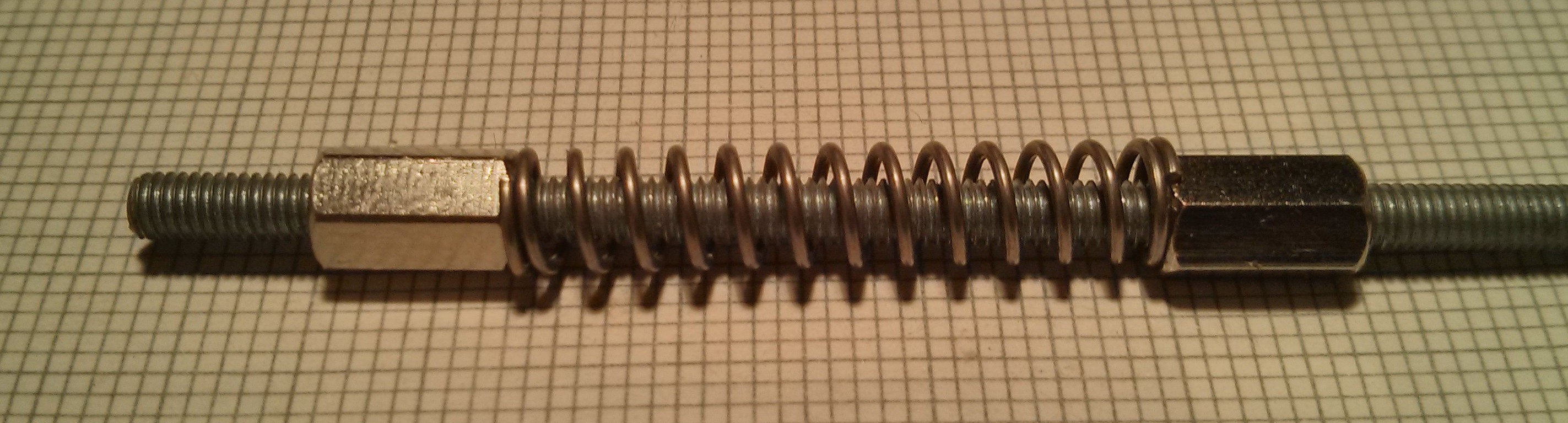
![]() It came to me when I had this threaded rod with those two standoffs laying on my bench along with a small box of misc parts among which were some springs. I was just sort of playing around with these parts wanting to see how far I could compress this quite stiff spring but then something interesting happened: The spring locked the two standoffs together pretty much eliminating the backlash, although it depends on how tight the spring is compressed. Of course, as it is the standoffs aren't completely locked, especially when the rod is turning fast but that's an easy fix.
It came to me when I had this threaded rod with those two standoffs laying on my bench along with a small box of misc parts among which were some springs. I was just sort of playing around with these parts wanting to see how far I could compress this quite stiff spring but then something interesting happened: The spring locked the two standoffs together pretty much eliminating the backlash, although it depends on how tight the spring is compressed. Of course, as it is the standoffs aren't completely locked, especially when the rod is turning fast but that's an easy fix.It's nothing revelatory but the way I stumbled upon it is somewhat amusing. As evidenced by the above example the general concept is a commonly known technique but the option of adjusting the pressure at any time makes for a nice feature.
-
Some links
11/12/2015 at 13:35 • 0 comments- You might know the MIT Machines That Make project that spawned the Mantis CNC Mill. Some other projects of their's that I find relevant to mine are:
- Another project from Ilan Moyer, the maker of the above PCBMill, is the Magic Mill which is just beautiful.
- The RepRap wiki has a lot of information on PCB milling as well
-
Mechanical 'design'*
11/11/2015 at 16:54 • 1 comment*not really design, more like doing something and seeing what works/sticks. Problem: Metal doesn't stick.
First attempt:
I think you see what I was going for here:
![]()
![]()
![]()
Square aluminium profiles as structural parts with the axis sliding on brass rods/tubes, all of which is driven by stepper motors salvaged from old printers and M3 threaded rods. If machined better this probably would have worked for applications with a very low load, like a plotter or maybe a 3D printer, but for a mill I think this was not a very good approach since the brass rods are nod as rigid as the square profiles.
The problem at the time was that my drill stand wasn't too precise anymore meaning right-angled holes ended up skewed. This was a major issue since in order to get identical spacings on pieces that belong together I would stack them up and drill them in one go. With a skewed drill-hole you can imagine that the holes on the pieces didn't end up having identical spacings. To make up for this I drilled out some holes such that the brass rods, for example, would be parallel which would have been fine for the lowest axis but not for the gantry above it. Also the shaft couplings were terrible.
1st redesign
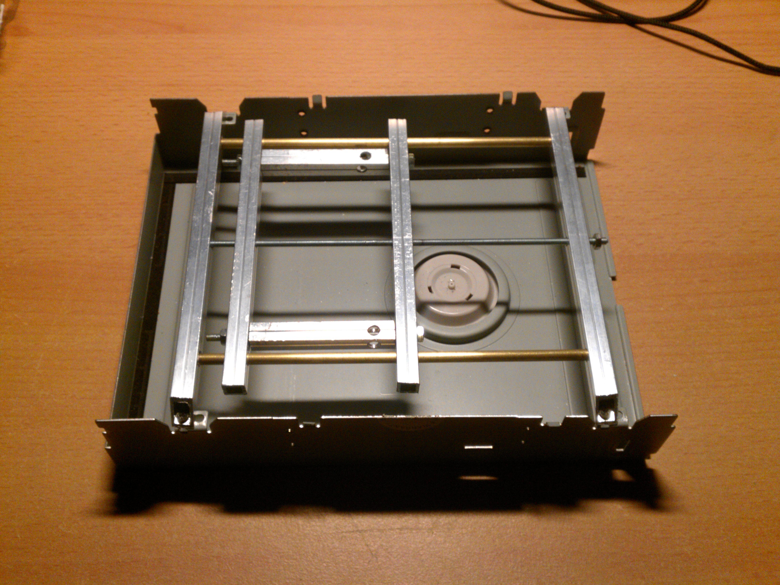
Initially I wanted to remake the parts from above but after my local hardware store changed management and stopped carrying the 8mm square aluminium profiles and I had to switch to the 10mm ones:
![]()
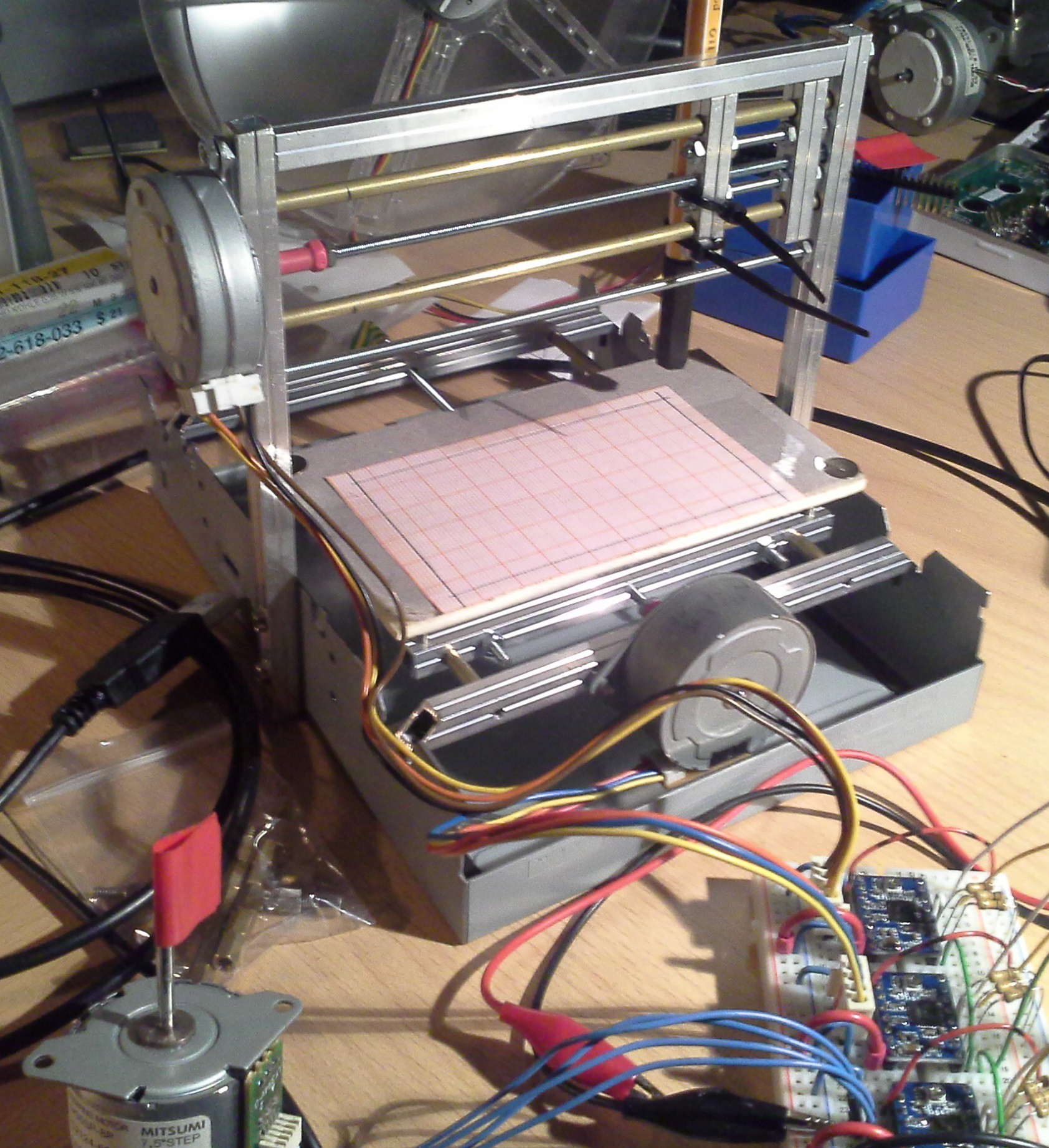
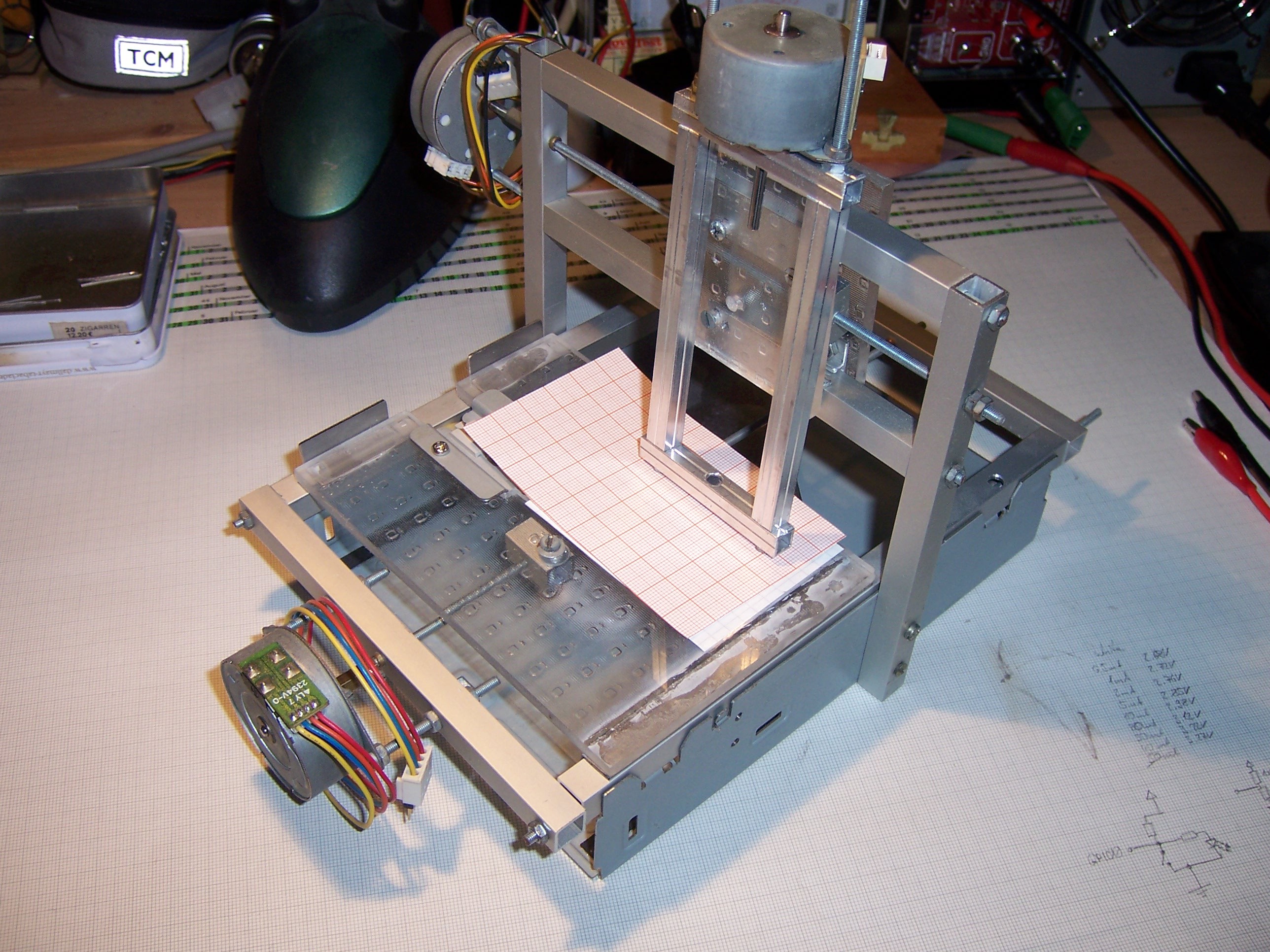
The previous z-axis had turned out pretty good so I decided to keep using it. The coupling between x and z axis shown above, however, didn't work as I had hoped so I scrapped that idea in favor of something more modular. You can barely make it out in this image which is the current state of the machine:
![]()
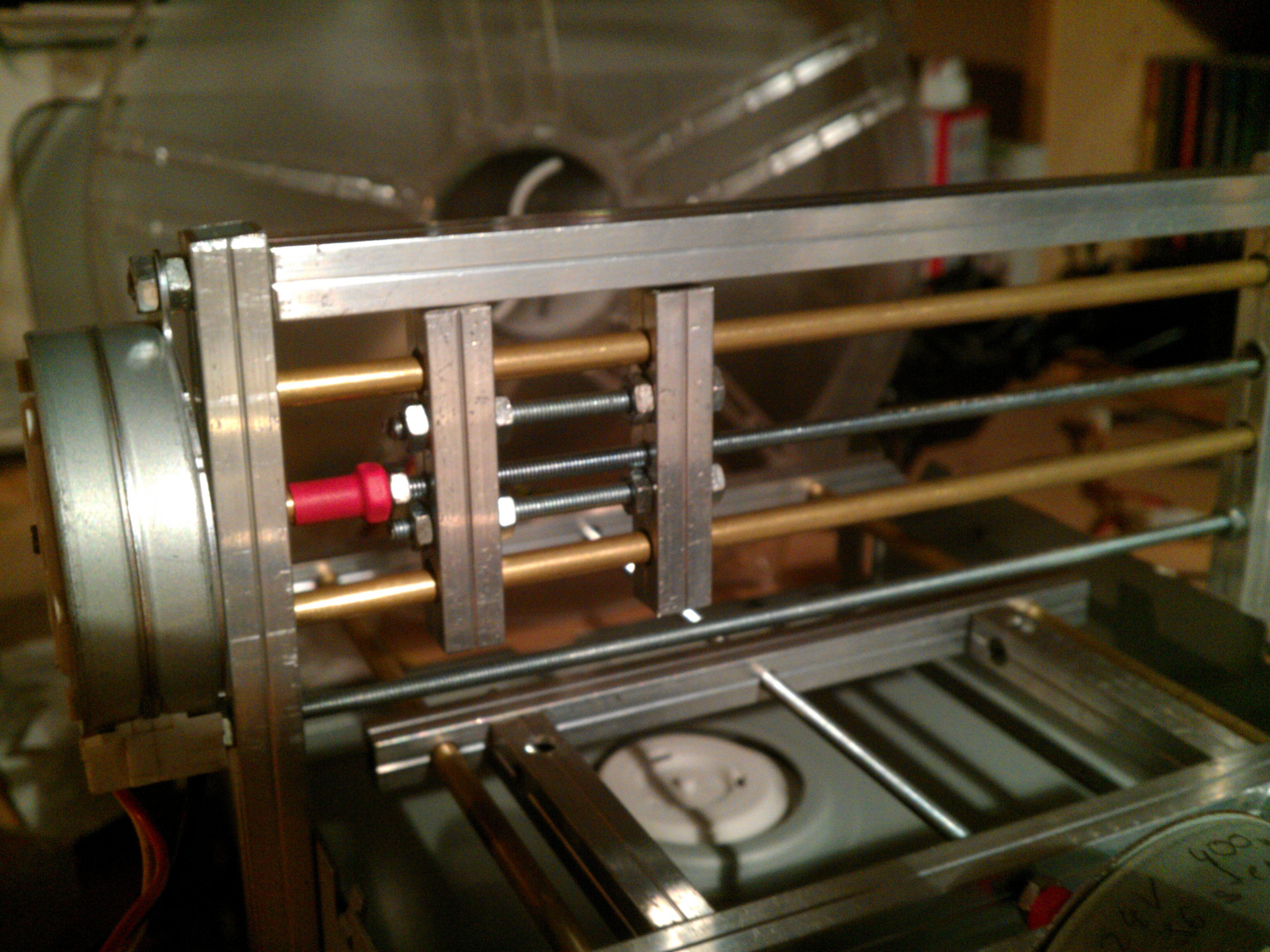
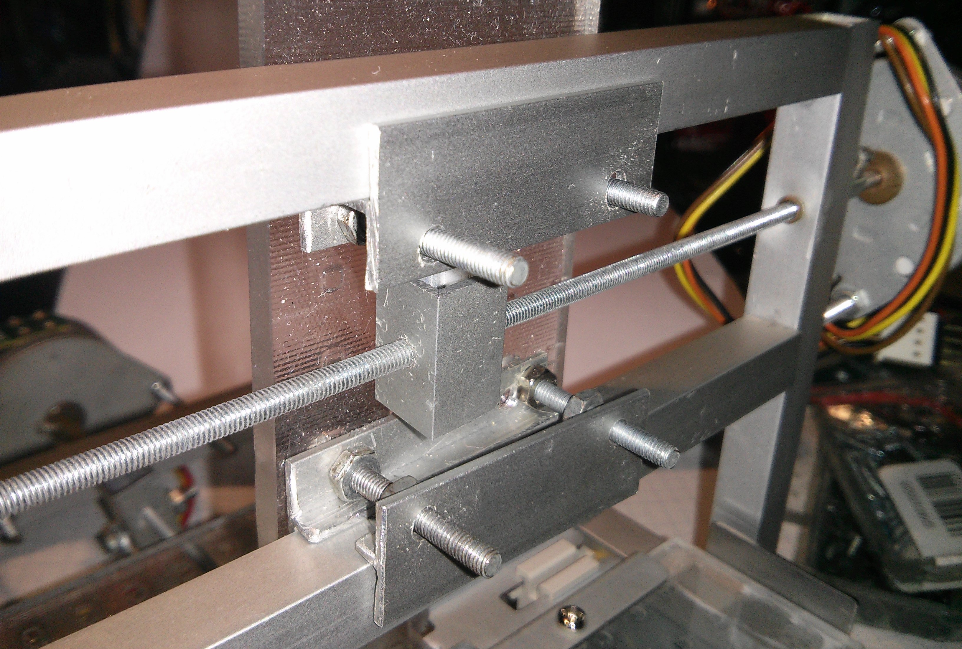
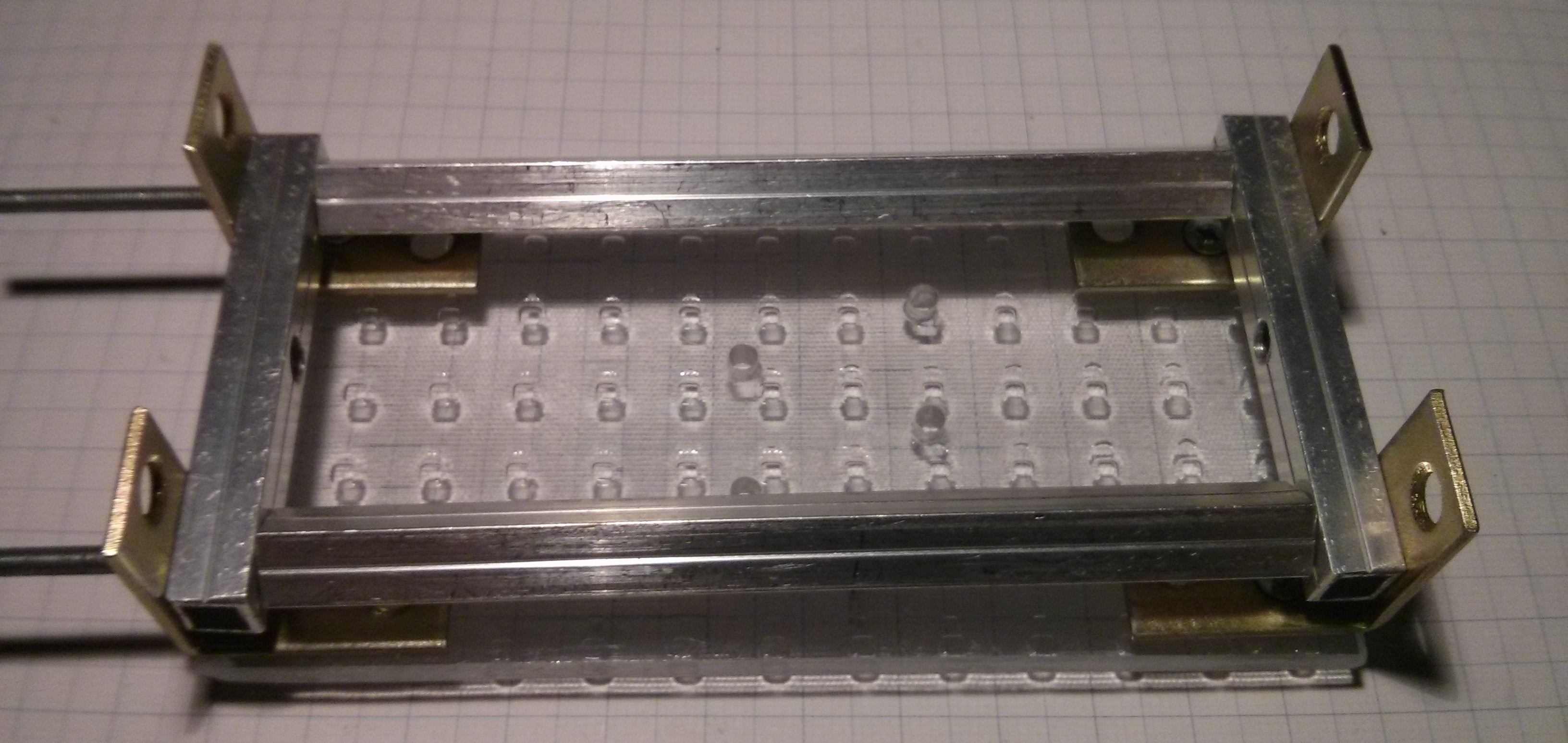
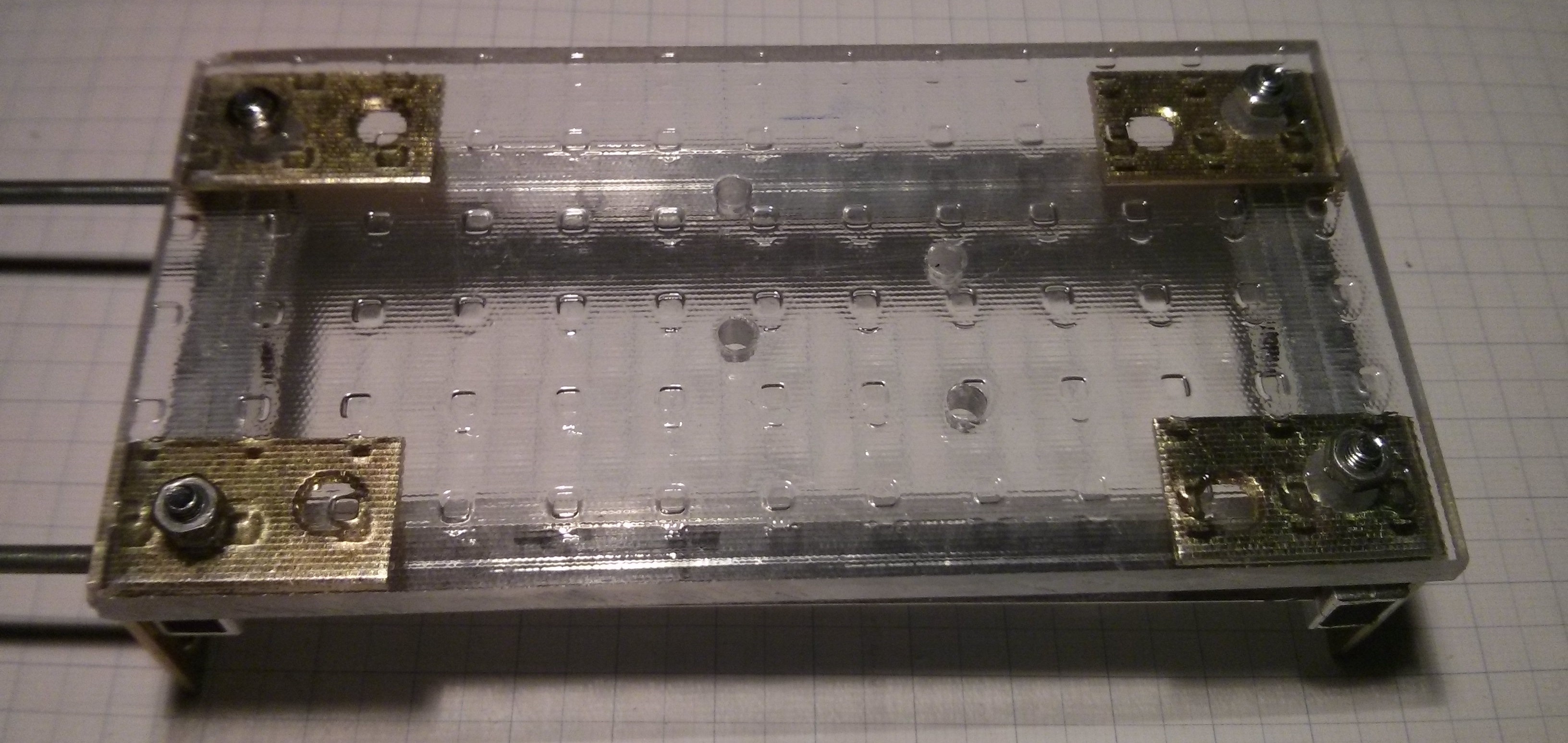
Close-up of partially assembled x-axis stage:
![]()
The stage of the x-axis consists of two pieces of acrylic that are held together by four screws. Also attached to these screws are four T aluminium profiles on which the stage slides on the bottom and top. The space between the T profiles/pieces of acrylic can be adjusted by nuts holding the profiles to the acrylic which should allow minimizing the slop of the stage. The same was planned for the z-axis such that this axis assembly could be attached to the machine by mounting the z stage to the x stage. At this point I thought about the friction between the aluminium profiles but decided to just see how it worked out.
The y-axis was built in such a way that the y stage is aligned in x direction to only one of the rails while the other rail only provides stability in z direction and has a pulley that pushes it against the first y rail.
The 'good' thing about this 'design' was that the distance between the rails and the threaded rod driving the stages was adjustable. By fastening the nuts at the ends of the threaded rods going through the rails they are clamped in place. Also the shaft couplings worked better.
The problem, however, was that I was unable to build the x stage precise enough. It kind of worked but was just frustrating so I stopped and thought about how I could improve my fabrication processes.
Redesign 1.1
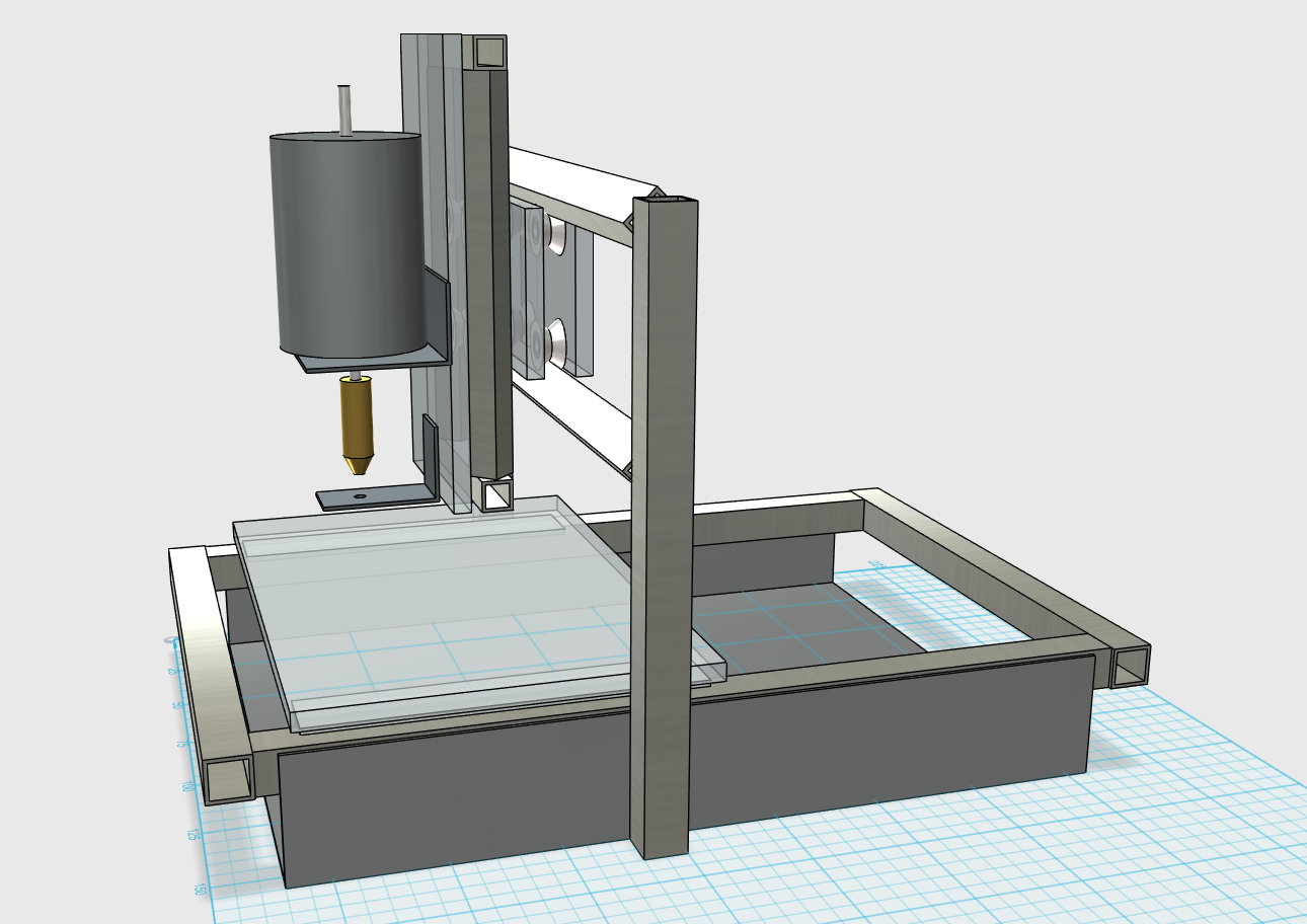
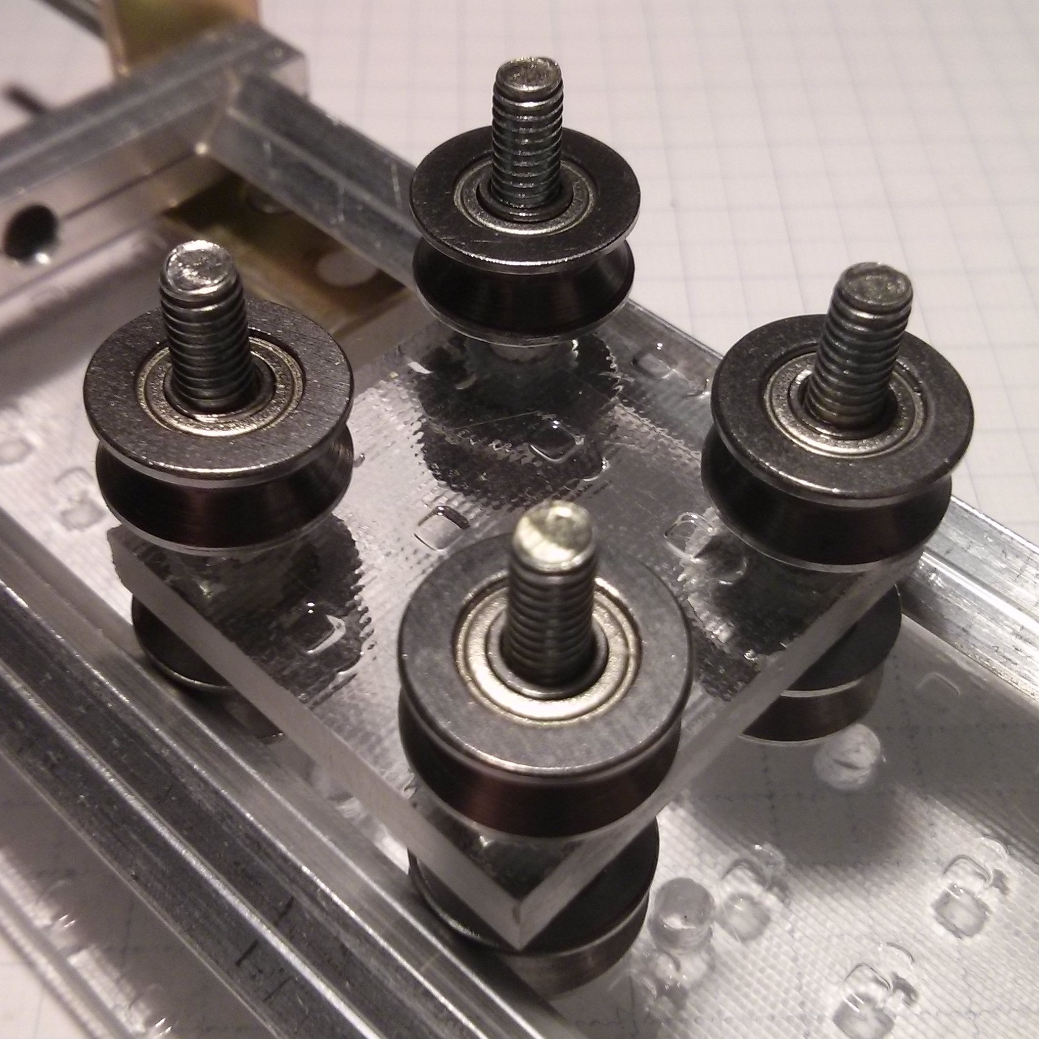
I initially went with the 'aluminium sliding on aluminium' option because the only alternative I saw at the time was to add a whole bunch of bearings, for the x stage alone 10-12. Only the other day I had the idea of turning the rails of the x (and z) axis by 45° and use v-groove bearings (4 per stage) that should stabilize the stage(s) in the remaining two directions. Something like this:
![]()
If you're familiar with my 'work' you probably know that I went straight to eBay and ordered some bearings, so unfortunately I'll have to wait for those to arrive to see if this idea is any good.
Update 2015-11-23: Added an image to redesign 1.1
Update 2016-03-03:
- Added image of partial x-axis stage to 1st redesign
Redesign 1.1 cont'd
Well, those v-groove bearings I ordered back in November/December never arrived so I had to reorder them. To my surprise the new ones actually shipped quite quickly so now I can finally do some more work on the machine.
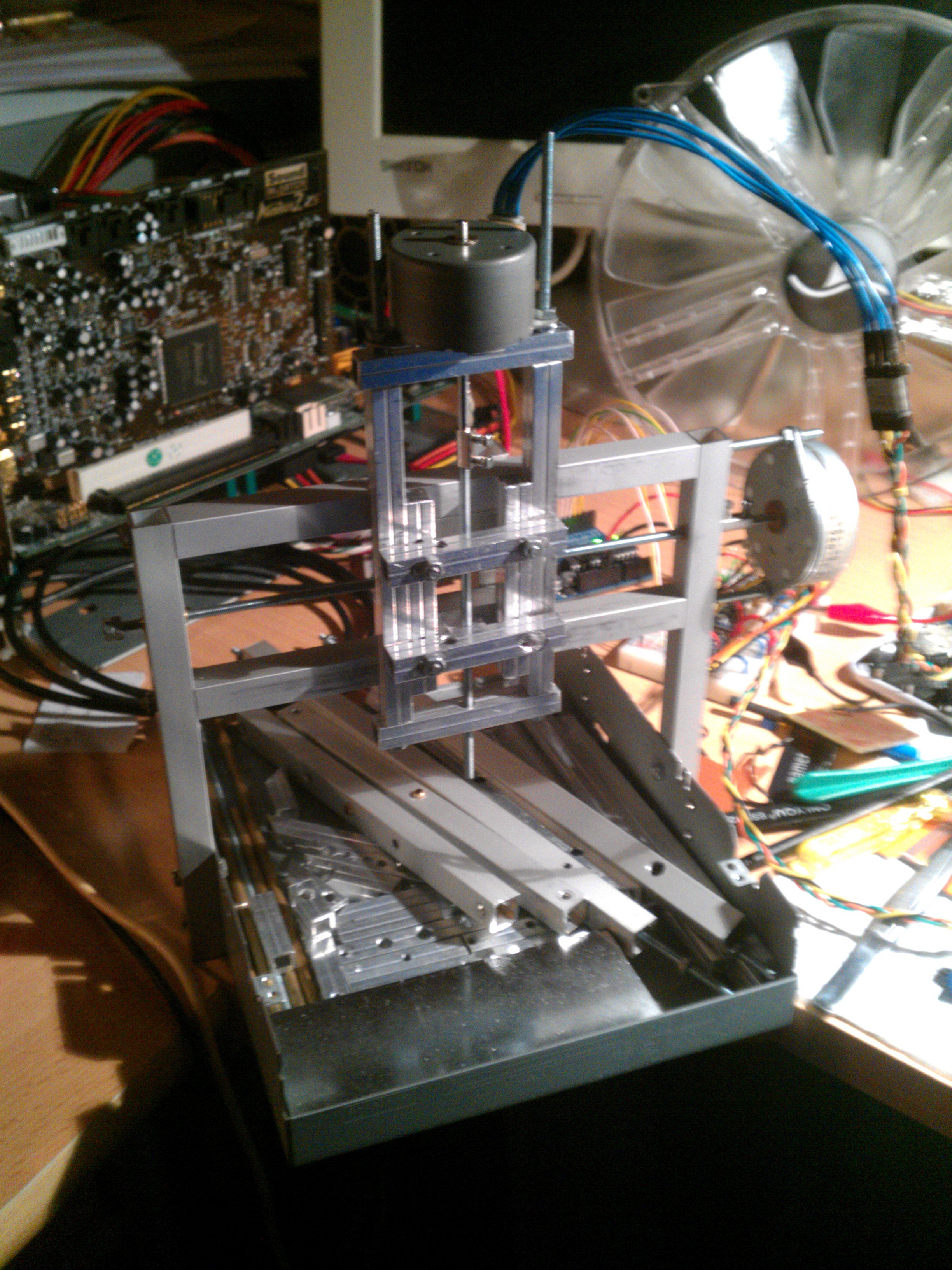
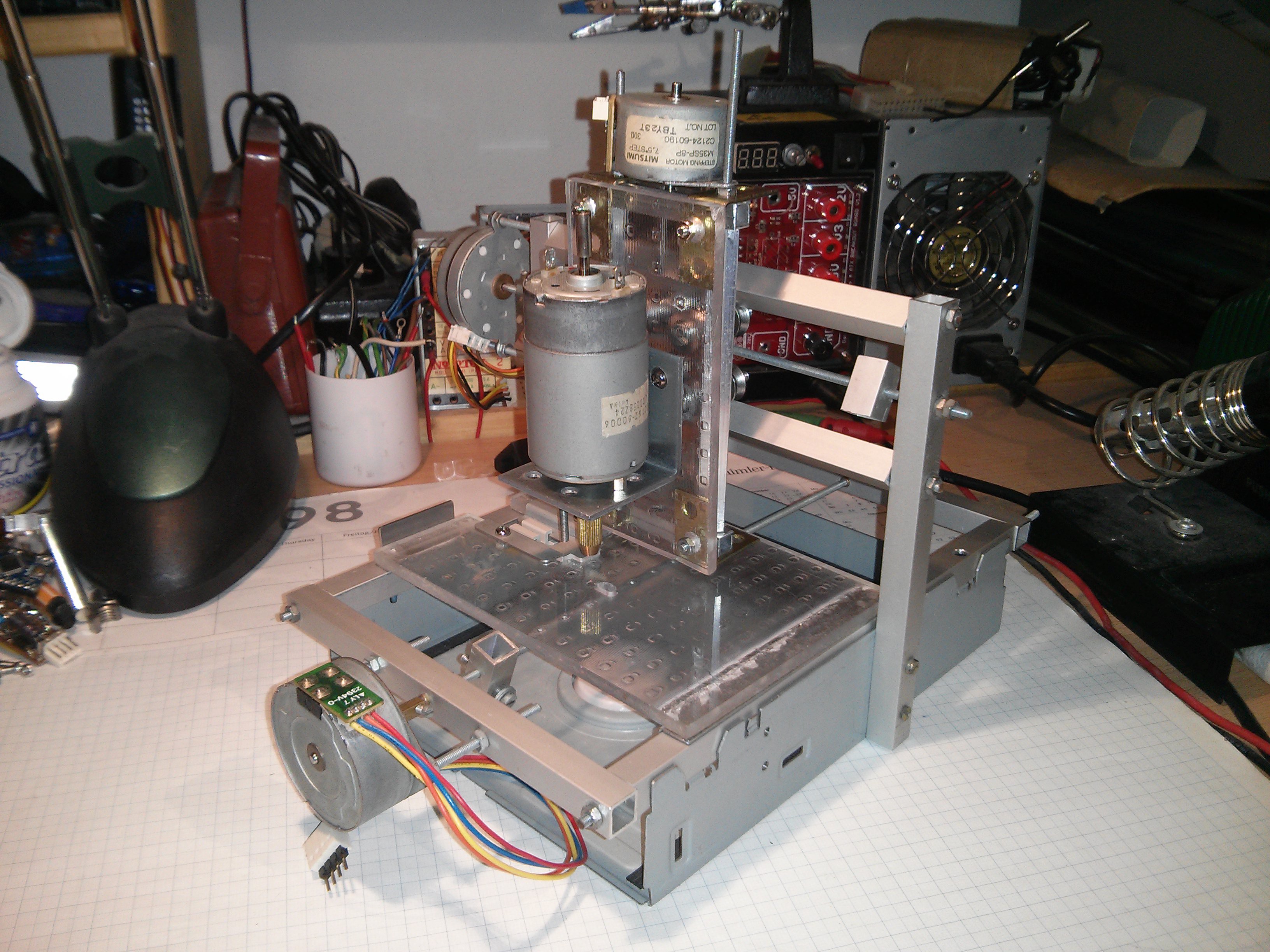
Basically I implemented my ideas outlined above and in the spindle log so here's an image of the current state of the machine:
![]()
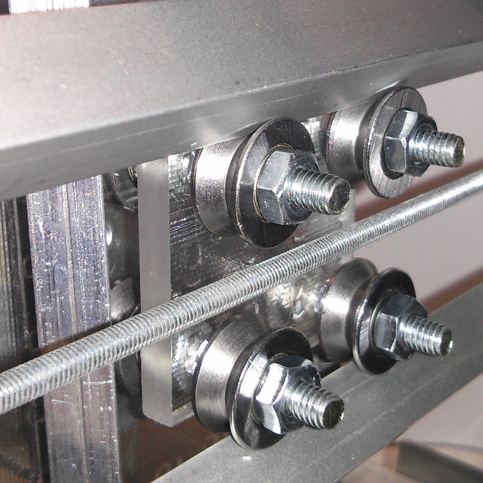
The main change is the new coupling of the z-axis to the x-stage:
![]()
![]()
The left image shows the coupling in the z-axis and the right image shows it (and the z-axis) in the x-axis.
The coupling is still missing something to be driven by the threaded rods but the general concept seems to work. As I mentioned above the x-axis rails are simply clamped between the vertical posts of the gantry by threaded rods running through the posts and the rails which allows the rails to be adjusted. But since the spacing of the z-axis rails is adapted from the mounting holes on the stepper motor adjustments is not possible here. This makes the z-axis quite loose and I still have to come up with a solution to this.
Initially I planned on having the bearings between two pieces of acrylic and maybe even a third one in the middle, as seen in the 3D model above. However, the space between the spindle mounting plate and the z-axis bearings was too small to fit one of those pieces so in order to test this concept I just assembled it this way for now. Also these M4 screws were too short to fit another acrylic piece on the back of the coupling (right image) but that should be easily fixed.
-
'Spindle'
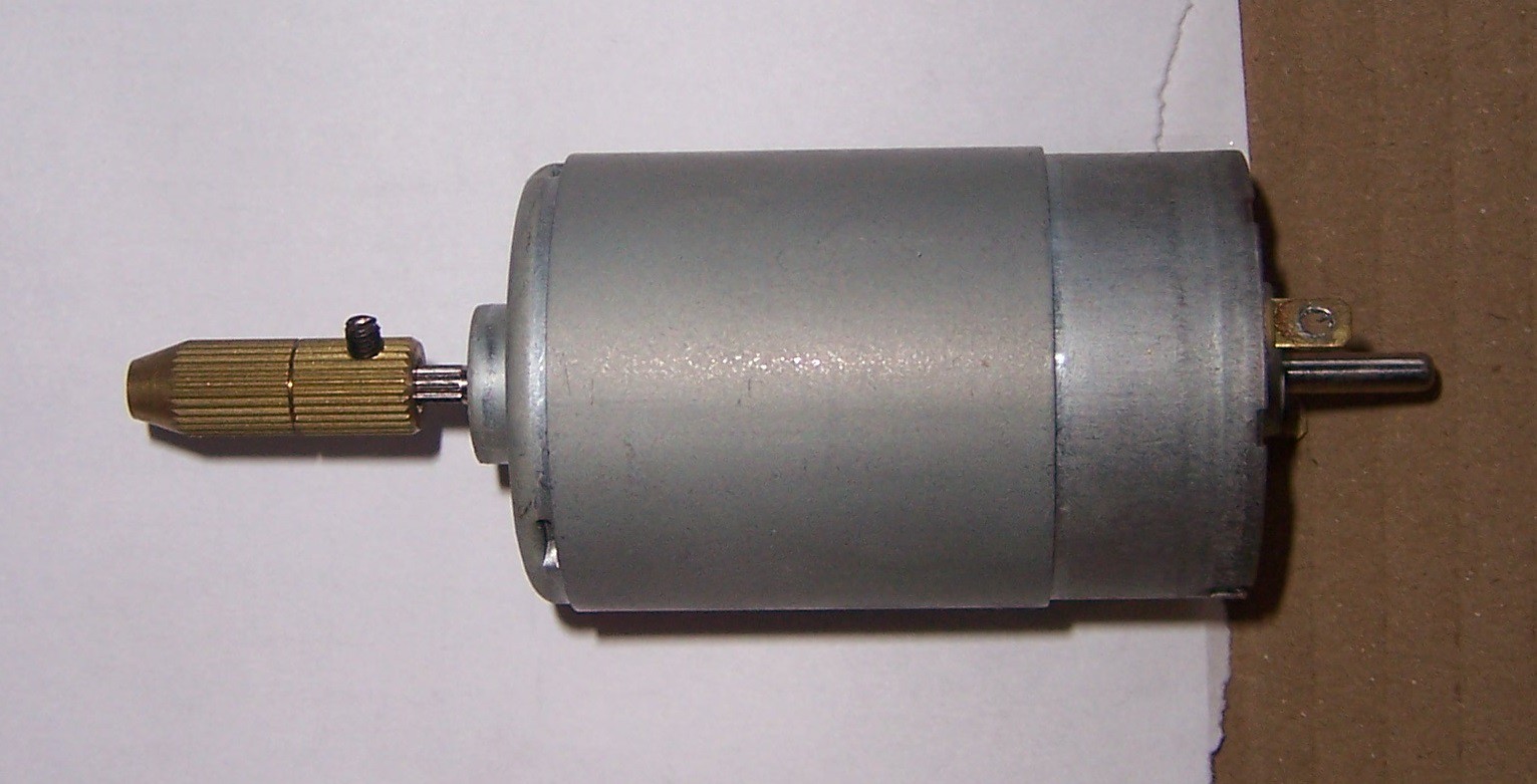
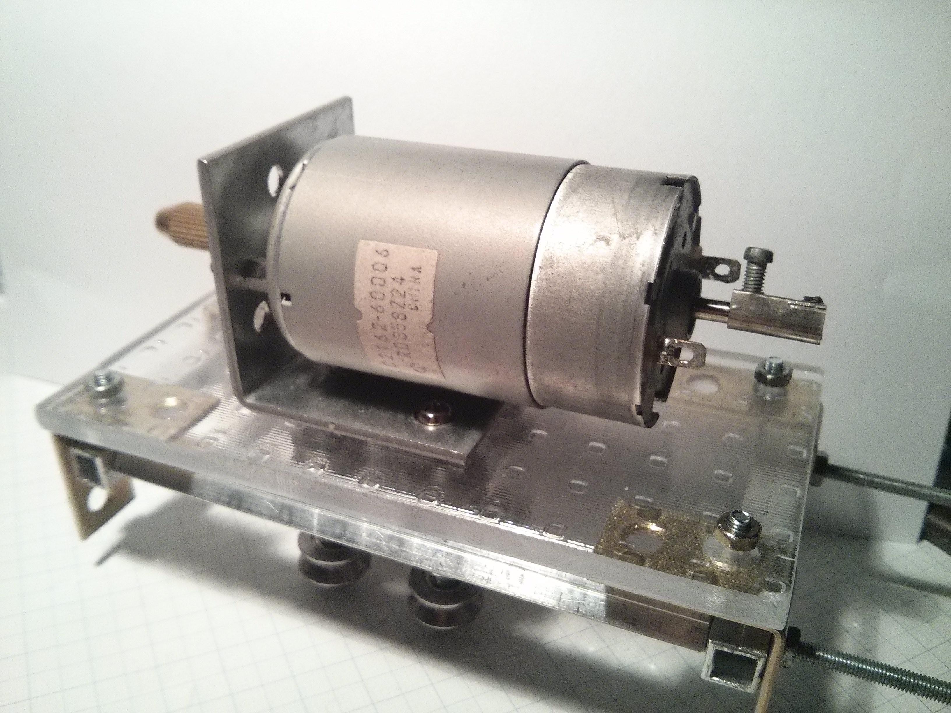
11/11/2015 at 16:39 • 7 commentsThought about using a rotary tool but I'm not sure if the machine will be able to handle it. For now the plan is to use a DC motor with one of those cheap self-tightening chucks (although that's not too different from a regular rotary tool):
![]()
Update 2015-11-24:
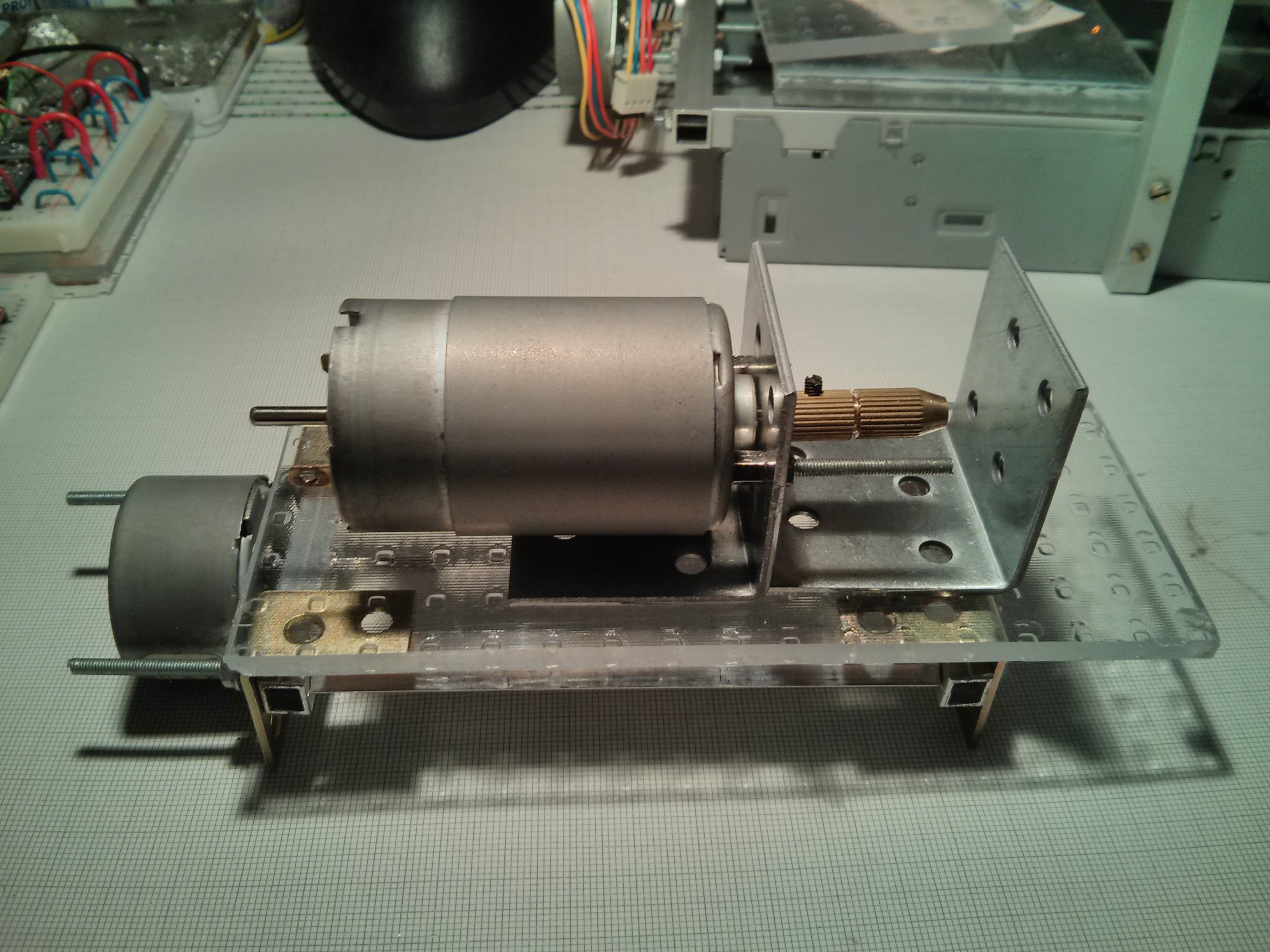
Some thoughts on how I'm going to mount it:
![]()
The motor is attached to an angle and will also be supported further on the left. Probably with some metal or acrylic pieces and a hose clamp to pull it tight against the base plate. The 2nd angle on the right will be a support/guide for the bit. I don't have any 1/8" inner diameter bearings (or drill bits for that matter) that could act as low friction guide so I guess a hole will have to do; it remains to be seen how I'm going to make that hole.
Update 2015-12-23:
I'm still waiting for the v-groove bearings and since I'd like to fabricate most of the next batch of parts in one go I haven't gotten too much done on this building wise. However, I did some tests on reducing wobbling of the bit. Initially the bit was off by about .5mm such that the very tip would move in a circle with a diameter of 1mm. I tried reducing it with a makeshift bushing but this had too much friction, causing the motor to slow down or even stall.
Pushing on the chuck such that the tip of the bit would go towards the center approximately halved the wobble and by rotating the bit inside the the chuck got it to a point where the wobble is negligible. The problem is that this chuck holds the bit only on a slim ring where its jaws close and the end of the bit that is inside the chuck has some space to move around. In hindsight this is pretty obvious but I just couldn't resist when I saw this chuck on eBay. I guess this will have to do in order to finally get the machine running for the first time and I'll make some improvements once I'm there.
Update 2016-03-03:
As I mentioned in the other log I had to reorder the bearings but now that the second order arrived I finally got back the motivation to continue work on this.
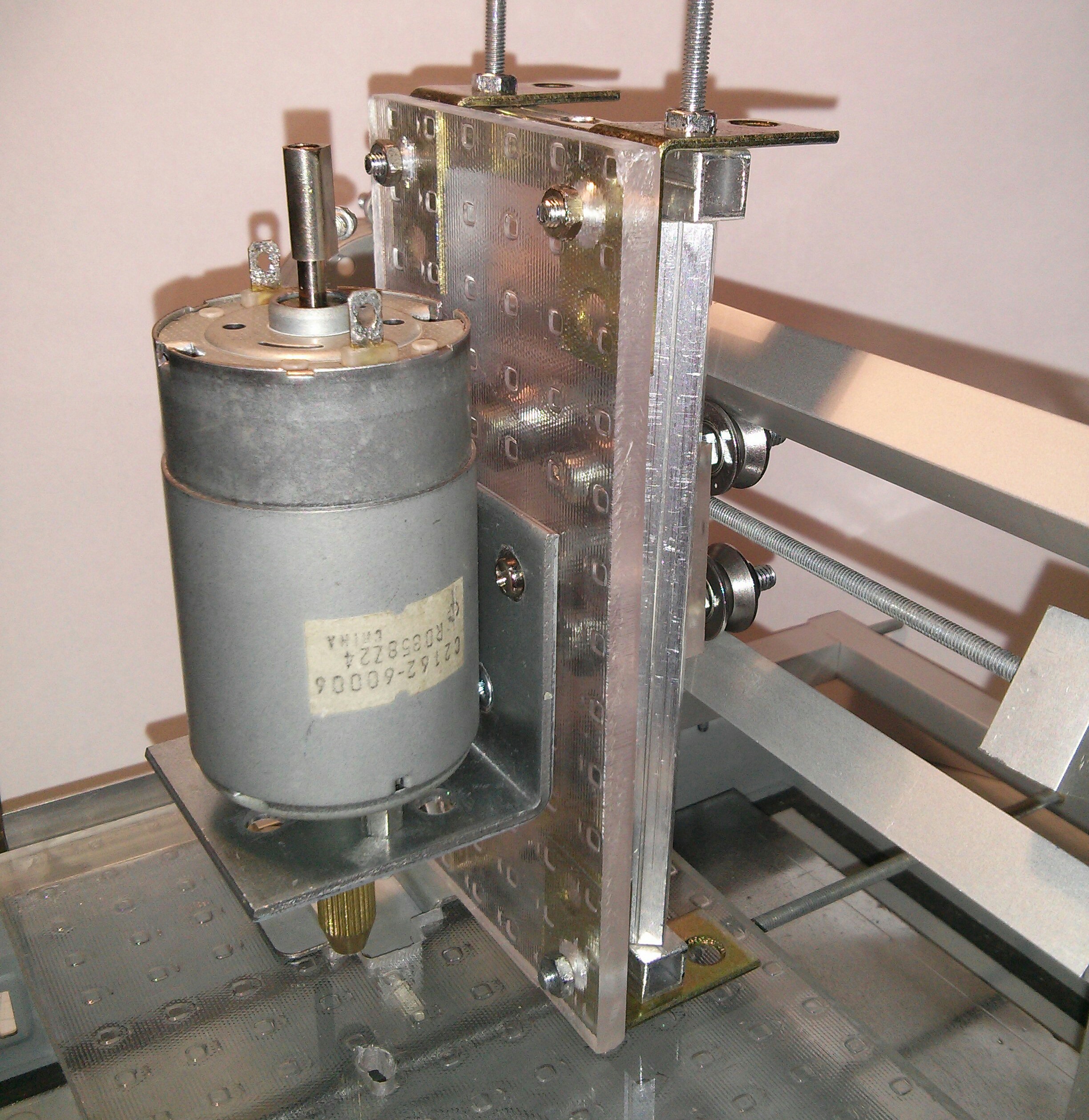
I pretty much just implemented the ideas outlined above so this is how the spindle mount looks like now:
![]()
![]()
![]()
I made some mistakes on the acrylic base plate since I rushed it a bit to get it done and see if this concept would work but those are primarily cosmetic so I could just make a new plate if I feel like it. I also still have to shorten the brass right angle pieces since they limit the machines range of motion a bit. Assembly of the spindle-mount/z-axis (shown below) was a bit of a pain because a couple of screws are obstructed - the ones under the motor on the metal angle, for example - but once done it seemed to work quite well. The optical flaws aside, the motor is mounted pretty sturdily to the z-axis so if I can get rid of the wobble of the bit it should work nicely.
![]()
-
Endstops
11/11/2015 at 16:32 • 0 commentsThey are not integrated yet but these are some ideas:
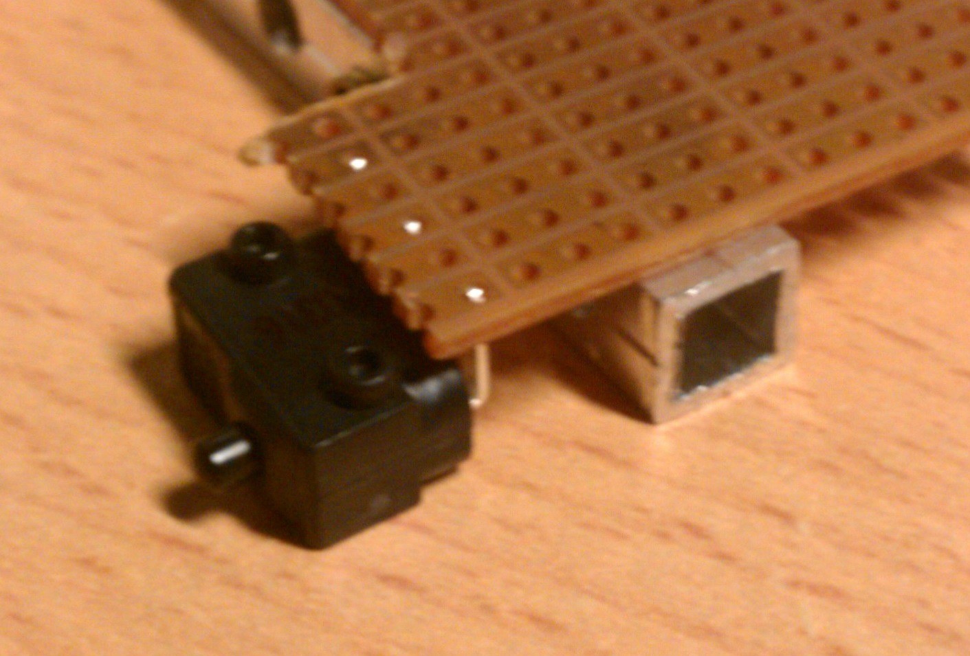
One of the ideas was to use buttons as endstops and mount them to the aluminium something like this:
![]()
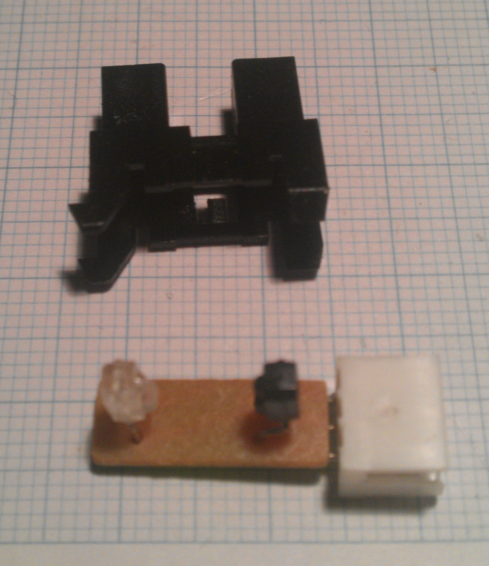
But since I also salvaged some of these optical interrupt switches from the printers it'd probably be a good idea to use these instead:
![]()
![]()
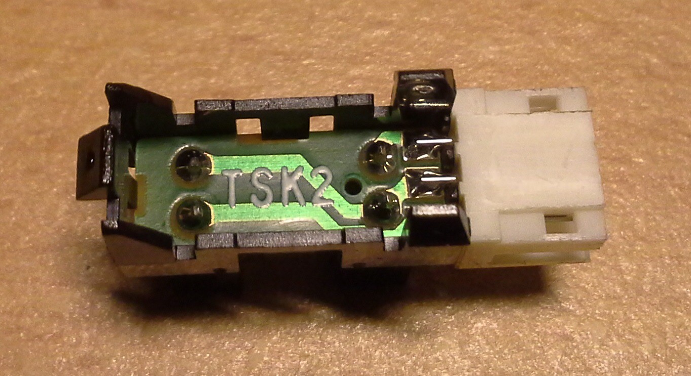
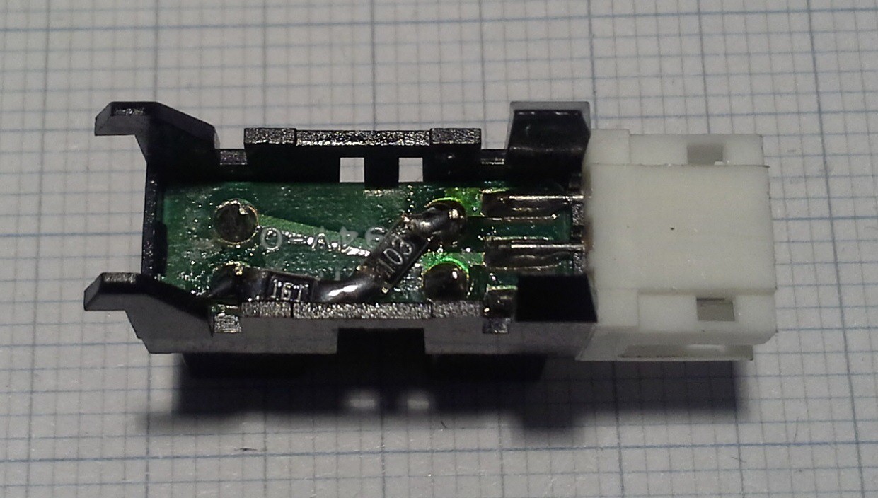
To be usable they require some more external components as described here (follow link for schematics) but the two essential resistors can also be fit directly on the PCB of the module like this:
With this modification I can feed the output of the module directly into the Uno without an additional board. Although I might make one to split the supply voltage for the three modules the final PCB for the the ATmega and the three StepSticks will probably have GVS headers for these endstops.![]()
-
Electronics
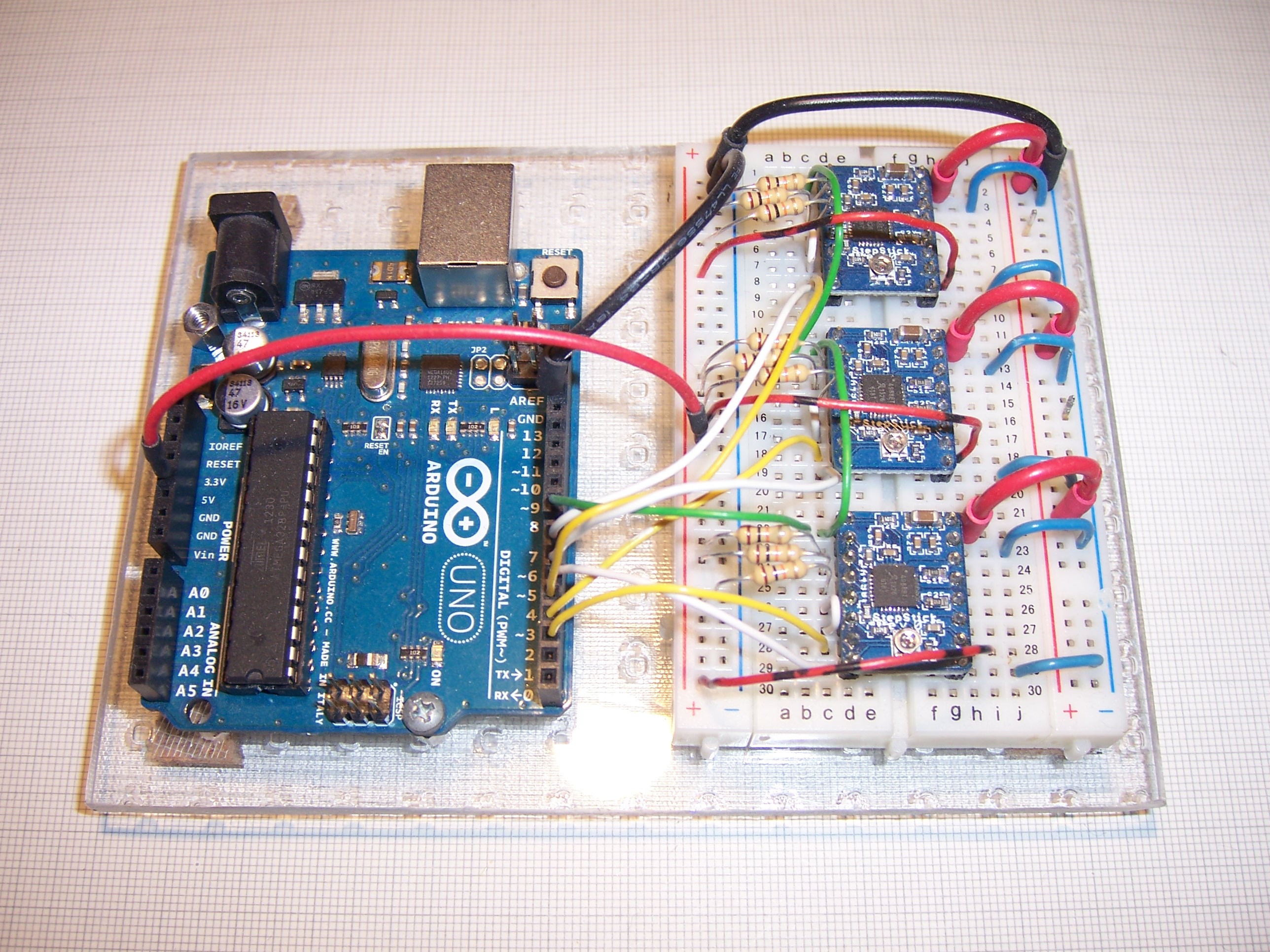
11/11/2015 at 15:33 • 0 commentsThe stepper motors seen in the main project image are salvaged from old printers. Maybe I'll write about them in more detail some other time.
To control the motors I'm using StepSticks which are really cheap on eBay and easy to use and are in turn controlled by an Uno.
![]()
As you can probalby guess from the image the Uno is running GRBL so nothing fancy here.
Computer Numerical Considerations
Not the full-fledged CNC project had.io deserves but the brain-dump @esot.eric asked for
 It came to me when I had this threaded rod with those two standoffs laying on my bench along with a small box of misc parts among which were some springs. I was just sort of playing around with these parts wanting to see how far I could compress this quite stiff spring but then something interesting happened: The spring locked the two standoffs together pretty much eliminating the backlash, although it depends on how tight the spring is compressed. Of course, as it is the standoffs aren't completely locked, especially when the rod is turning fast but that's an easy fix.