-
1Step 1
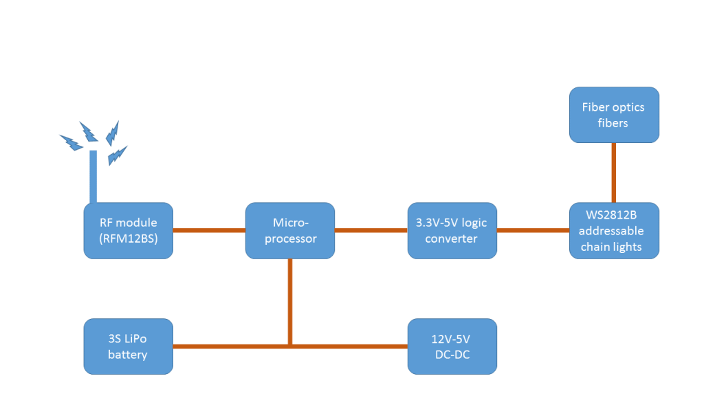
Block diagram & electronics:
![block_digram]()
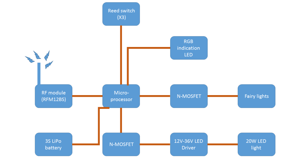
The 3 reed switches were mounted vertically in the aluminum part of the staff and connected to the micro-processor – in this case an Arduino 3.3V. I used 3 sensors in order to created different function that the staff can preform. Each sequence (or combination) does one thing or not do anything at all.
To the micro-processor there are also connected:
- Extra reed switch(4 in total) for future use. Probably not gonna be useful anymore, when I designed it I though I would need more switches.. than I decided to implement the sequence mechanism…
- Regular 5mm small RGB LED – this is a multi purpose LED. During normal operation this LED blink for 100ms every 5 seconds. This blink is a battery voltage indication. Because LiPo batteries could be damaged if going below 3V per cell I wanted to create a visable voltage indication which means: on 12.6V – 10.8V the LED blinks in green, on 10.8V – 9.6V the LED blinks in blue and below 9.6V the LED goes very fast blink in red.The second use of this LED is to give the user (aka warlock heheh) indication that a command was received after on of the reed switches was triggered. The first reed triggers the red light, the second triggers the green and the third one triggers the blue. This means for example that if my target sequence is is to light the soft staff head light is 1st reed switch and than 2nd reed when I’ll trigger the first one the LED will go from voltage indication to solid red(1st reed) and when the 2nd reed will be triggered it will go to green, the soft staff head light will toggle off or on(depending on the previous state) and the LED will go back to it voltage indication use..
- RF module – the cloak itself is controlled via the staff. The color can be changed, the patterns: flickering, fading in\out animations etc.. or it can be turned of completely.. go into invisible mode. The command are being transmitted to the cloak using 4 bytes. Each of three first byte contains the RGB values for the cloak and the 4th one contains the desired pattern.
- I used RFM12BS RF module – it works on 3.3V TTL. This is the reason I used 3.3V Arduino,
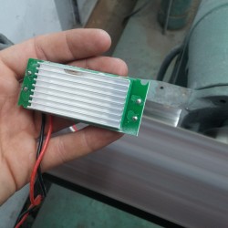
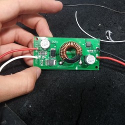
- Two N-MOFSETs – one controls the staff’s head light – soft or high. This N-MOFSET is connected to 12v to 36V DC-DC LED driver that controls the staff head light LED.The second one controls the fairy lights around the staff itself.
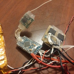
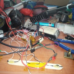
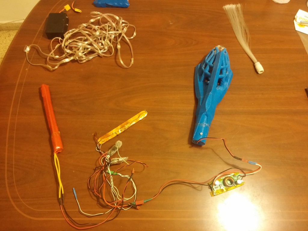
And the whole set:
Cloak - Block diagram
Warlock costume – Staff & invisibility cloak
What I had in mind is some kind of invisibility cloak. Unfortunately it not existing yet but this is the closest thing...
 MDreamer
Discussions
Become a Hackaday.io Member
Create an account to leave a comment. Already have an account? Log In.