ottoragam
-
The commercial side of this thing
06/03/2016 at 23:53 • 0 commentsI've been working with James Newton, of Linnistepper fame, on an open source commercial low cost closed loop motor conversion system. An encoder board is available for sale, along with a PIC based PID controller.
![https://cdn.hackaday.io/images/5569361461622297516.jpg]()
The relevant links are here:
Hakcaday.io project
https://hackaday.io/project/11418-massmindorg-abosoluteincremental-rotary-encoder
Purchase here!
http://techref.massmind.org/techref/io/sensor/pos/enc/ENC1.htm
http://techref.massmind.org/techref/io/servo/BOBPID.htm
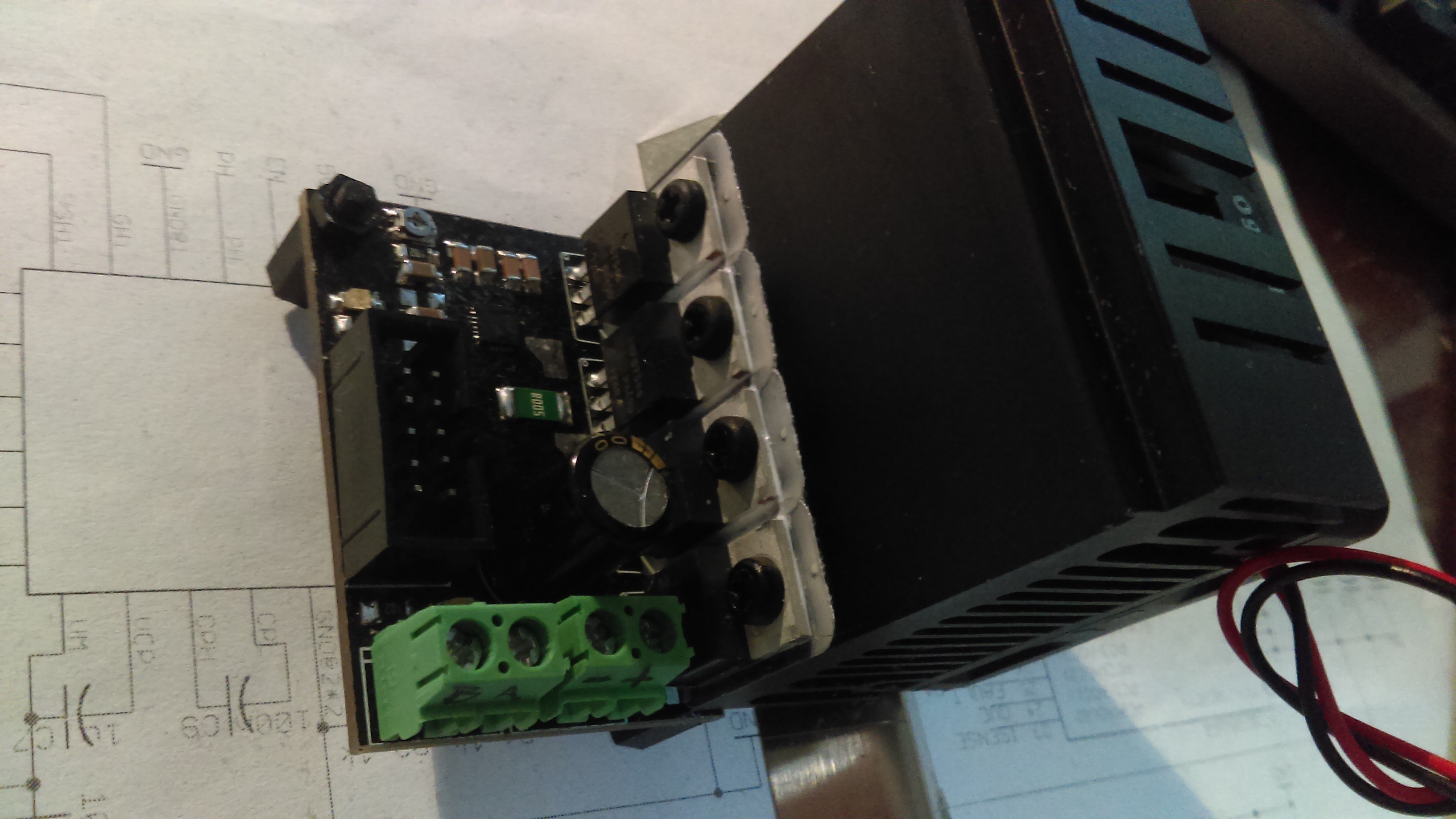
This project may also be of interest to some of you. It is a low cost 40V 18A H bridge based on the same FET driver as my smaller servo drive project, with some easier to cool transistors.
![https://cdn.hackaday.io/images/5344591461622861291.jpg]()
https://hackaday.io/project/11419-massmindorg-40-v-15-a-output-dc-motor-drive
-
Assembled and tested: check
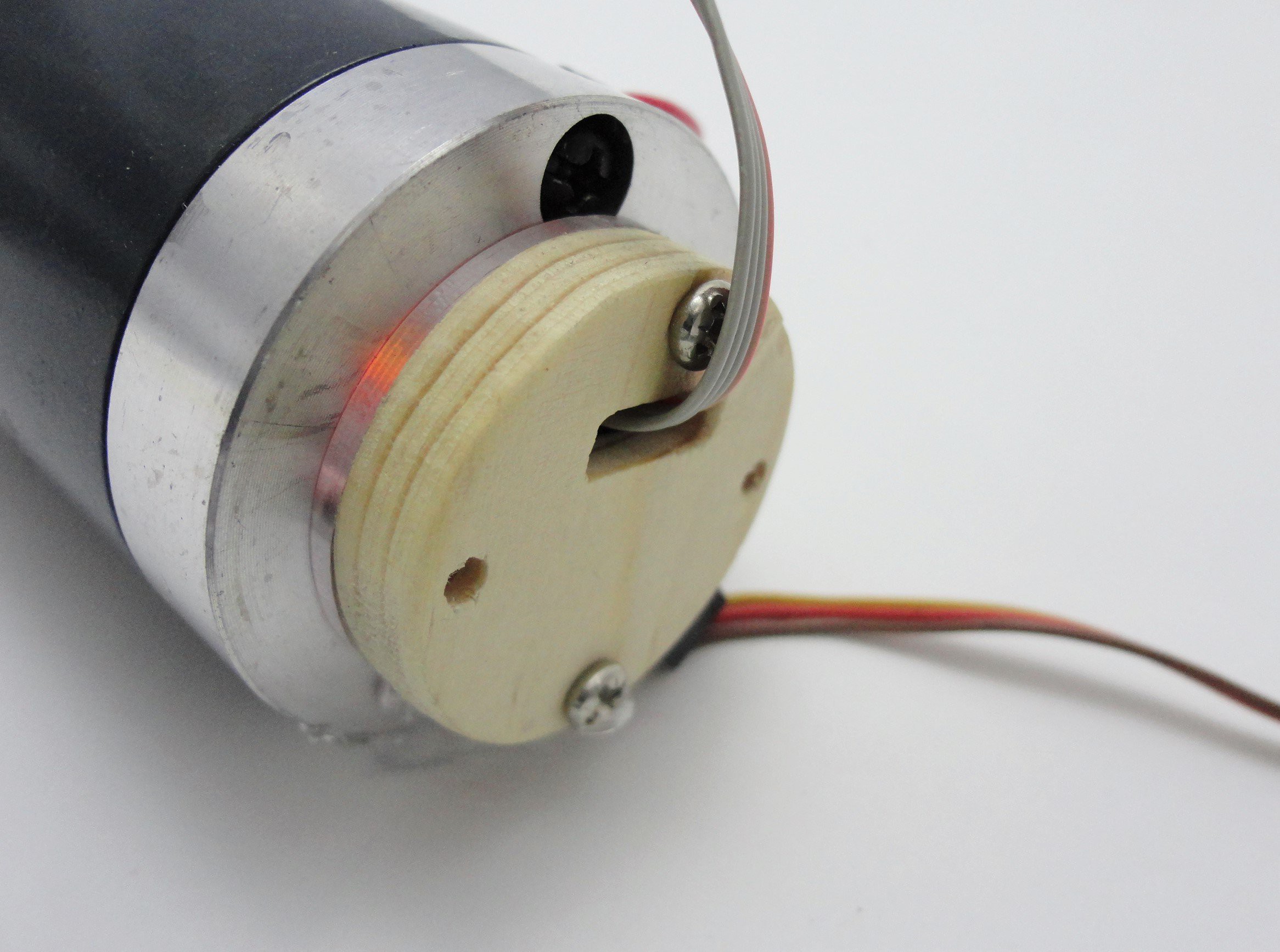
11/23/2015 at 22:56 • 0 commentsEverything is working perfectly! I assembled the cable harness for the sensor using a 4 way JST-PH connector and multiwire cable. All the work was done in less than 5 minutes thanks to my recently acquired a cheap crimping tool (you can see the harness in build instruction photos).
The sensor was mounted on a DC motor in order to provide feedback to a PID servo drive I'm working with.
-
Milled case: check
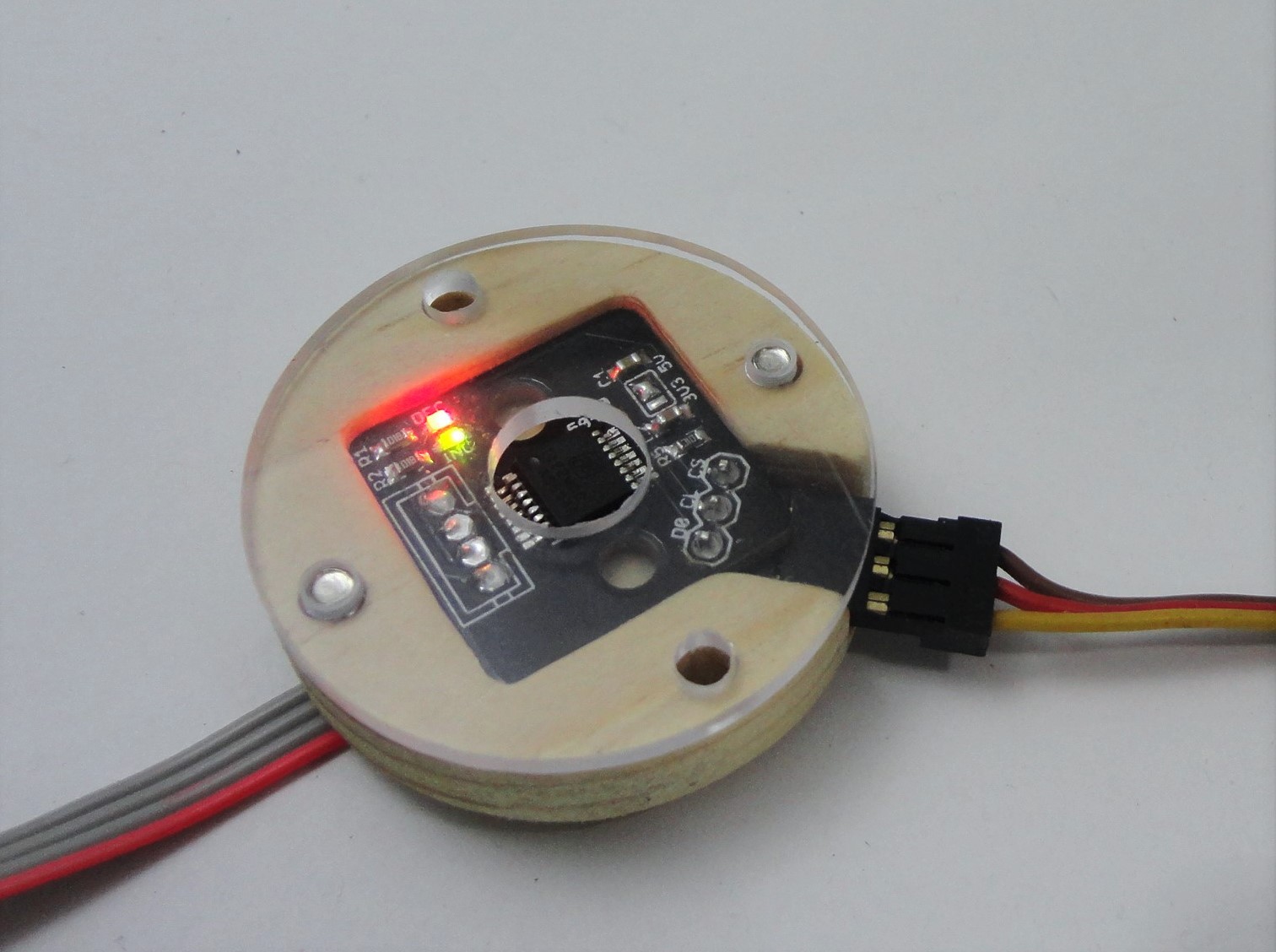
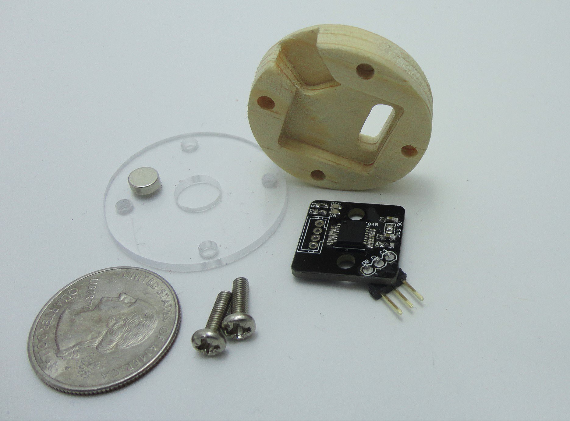
11/20/2015 at 13:59 • 2 commentsThe PCB can be mounted using the two holes next to the IC, but I also wanted to have an enclosure for the module for scenarios that demand more protection. I designed and milled a case for the PCB (relevant design files in the repo). I made the base from pine (my plan was to use acetal or polyethylene, but I didn't have any of those materials stocked). The cover is made from clear acrylic, with two of the four bolt holes drilled to accept threading with a 3 mm tap.
![]() Here's the whole thing assembled. Notice that the IC must be facing the acrylic part.
Here's the whole thing assembled. Notice that the IC must be facing the acrylic part.![]()
Mounting the case onto something like a motor prevents the user from being able to see the alignment LEDs directly. This is where the acrylic cover comes into play, because it allows the light to be seen on the edge of the part.
![]()
-
Assembled prototype: check
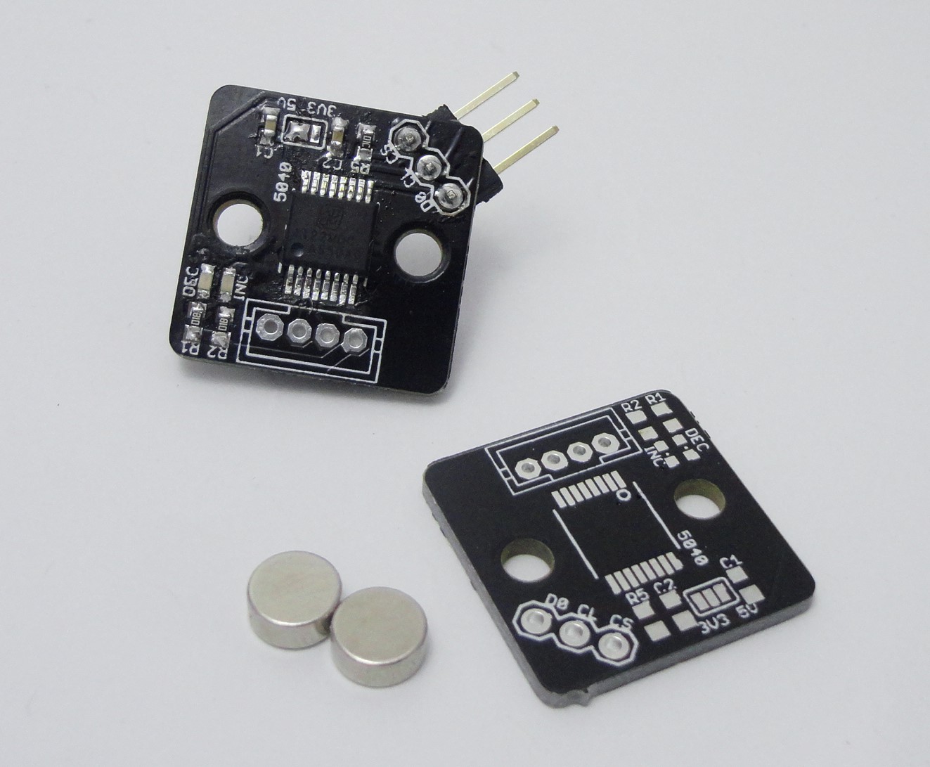
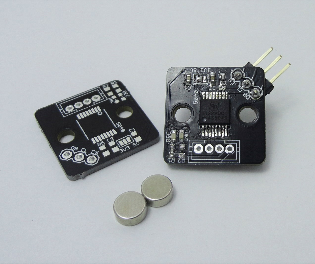
11/15/2015 at 00:06 • 0 commentsThe first PCB is ready, have a look at it!
![]()
![]()
There are some design choices I would like to point out: rounded corners, separate connector for power/quadrature channels and programming, small size.
First, the rounded corners are important if one is going to machine an enclosure for this. Milling can only leave an interior corner with a radius as small as the endmill one's using.
With respect to the connectors, it is useful to have few signals in it. Instead of using the typical piece of ribbon cable for the signals, I planned to fabricate my own cable, using a JST-PH connector and shielded multiconductor cable for improved flexibility and noise inmunity. Good flexible multiconductor cable could get expensive, so it's better to use as few conductors as possible, leaving the signals that are not used all the time (i. e. spi programming header) on a secondary connector.
Many of the AS5040 projects out there that I found are more focused on being a breakout board for experimenting with this chip, and thus they're big, include things that are not needed for standalone operation, or are not really a finished product, and that's why I decided (also, The Square Inch Project) to create this board.
Magnetic Incremental Rotary Encoder
A compact solution for your closed loop positioning requirements

 Here's the whole thing assembled. Notice that the IC must be facing the acrylic part.