Jeroen van der Velden
-
Inputs Part 1 (Pro Micro)
04/07/2016 at 09:57 • 0 commentsHere is they layout and code to connect up to 9 pieces of Truck Hardware (2-wire) to an Arduino Pro Micro Board:
![]()
To download the Fritzing click HERE
Arduino IDE Code:
void setup()
  {
  pinMode (2, INPUT_PULLUP);
  pinMode (3, INPUT_PULLUP);
  pinMode (4, INPUT_PULLUP);
  pinMode (5, INPUT_PULLUP);
  pinMode (6, INPUT_PULLUP);
  pinMode (7, INPUT_PULLUP);
  pinMode (8, INPUT_PULLUP);
  pinMode (9, INPUT_PULLUP);
  pinMode (10, INPUT_PULLUP);
  Keyboard.begin();
  } // end of setup

void loop()
  {
  //if the button ispressed
  if(digitalRead(2)==LOW)
    {
    //charrcter to be send
    Serial.print("a");
    Keyboard.print("a");
    } // end of state change

    //if the button ispressed
  if(digitalRead(3)==LOW)
    {
    //charrcter to be send
    Serial.print("b");
    Keyboard.print("b");
    } // end of state change

    //if the button ispressed
  if(digitalRead(4)==LOW)
    {
    //charrcter to be send
    Serial.print("c");
    Keyboard.print("c");
    } // end of state change

    //if the button ispressed
  if(digitalRead(5)==LOW)
    {
    //charrcter to be send
    Serial.print("d");
    Keyboard.print("d");
    } // end of state change

    //if the button ispressed
  if(digitalRead(6)==LOW)
    {
    //charrcter to be send
    Serial.print("e");
    Keyboard.print("e");
    } // end of state change

    //if the button ispressed
  if(digitalRead(7)==LOW)
    {
    //charrcter to be send
    Serial.print("f");
    Keyboard.print("f");
    } // end of state change

    //if the button ispressed
  if(digitalRead(8)==LOW)
    {
    //charrcter to be send
    Serial.print("g");
    Keyboard.print("g");
    } // end of state change

    //if the button ispressed
  if(digitalRead(9)==LOW)
    {
    //charrcter to be send
    Serial.print("h");
    Keyboard.print("h");
    } // end of state change

    //if the button ispressed
  if(digitalRead(10)==LOW)
    {
    //charrcter to be send
    Serial.print("i");
    Keyboard.print("i");
    } // end of state change

  } // end of loop
So input 2+GND will send an "a". Input 3+GND will send a "b" and so on. Feel free to change the "#" to anything else!
-
Direction Indicators Part 2
03/27/2016 at 18:15 • 0 commentsHere are the details for connecting the Direction Indicators to an Arduino Pro Micro:"
-
Scania 4 Cluster Demo
03/26/2016 at 18:32 • 0 commentsThis is a video (bot mine) about a Scania 4-Series Cockpit running on ETS2.
I will investigate it because its way nicer than a VW Polo Instrument panel for my Simulator.
-
Wiring continued
03/19/2016 at 14:57 • 0 commentsPicture Below:
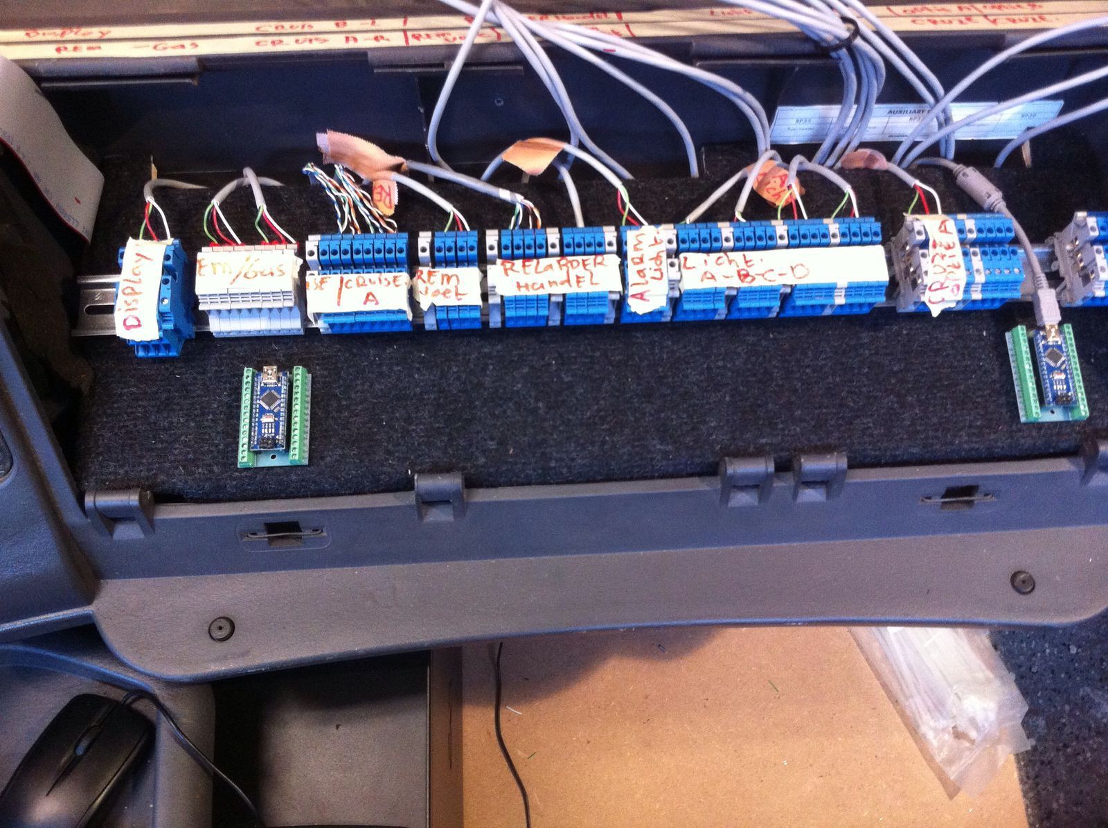
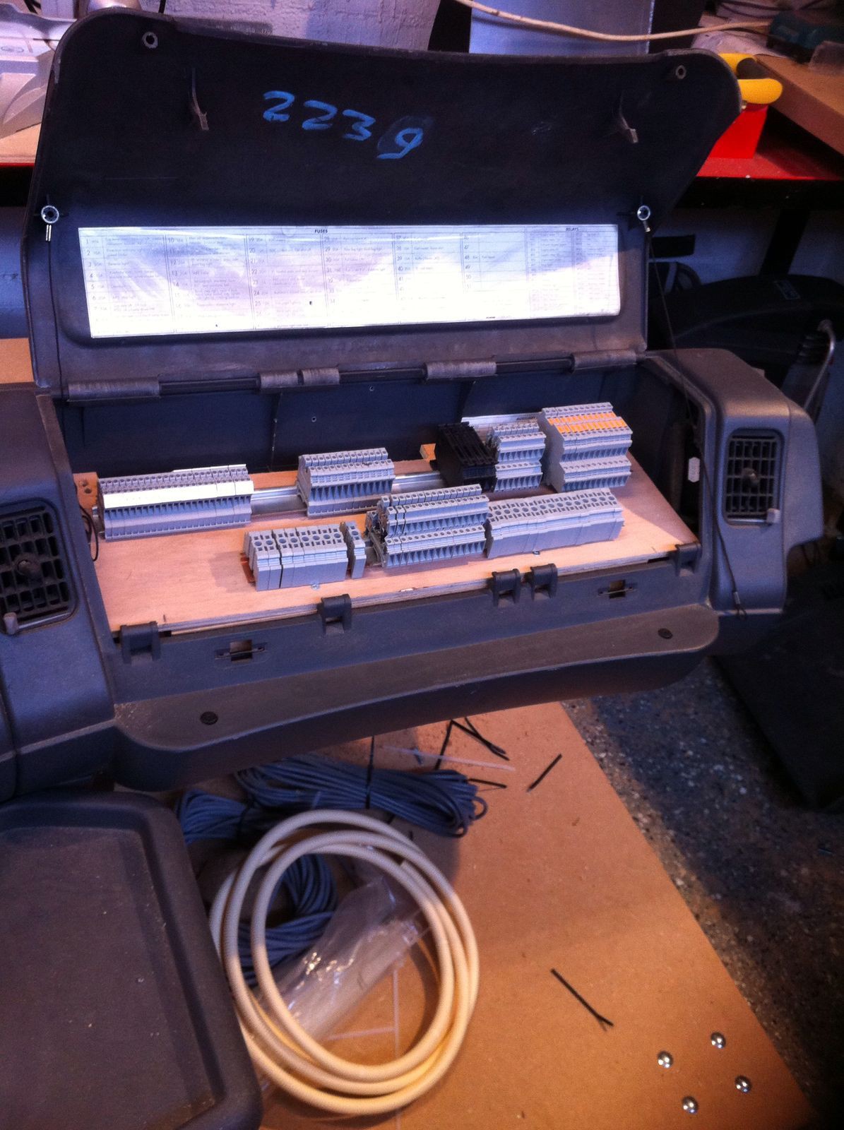
All wiring will be terminated via Phoenix Contact (Blue and Grey things). I wanted to centralize all wiring to one spot so it will be easier to mod, test and change Arduino Boards later-on. The Flat-Cable on the left goes to the VW Polo Cockpit.
![]()
Labeling will be done nicely later, keep watching my LOGS!
![]()
-
Steering first run!
03/14/2016 at 19:53 • 0 commentsHere is a short video of the very first ETS2 Run with the Simulator!
I know, lots of work to be done here. We need to align the steering wheel, fix the steering shaft so it produces less noise etc. Keep watching!
Picture below:
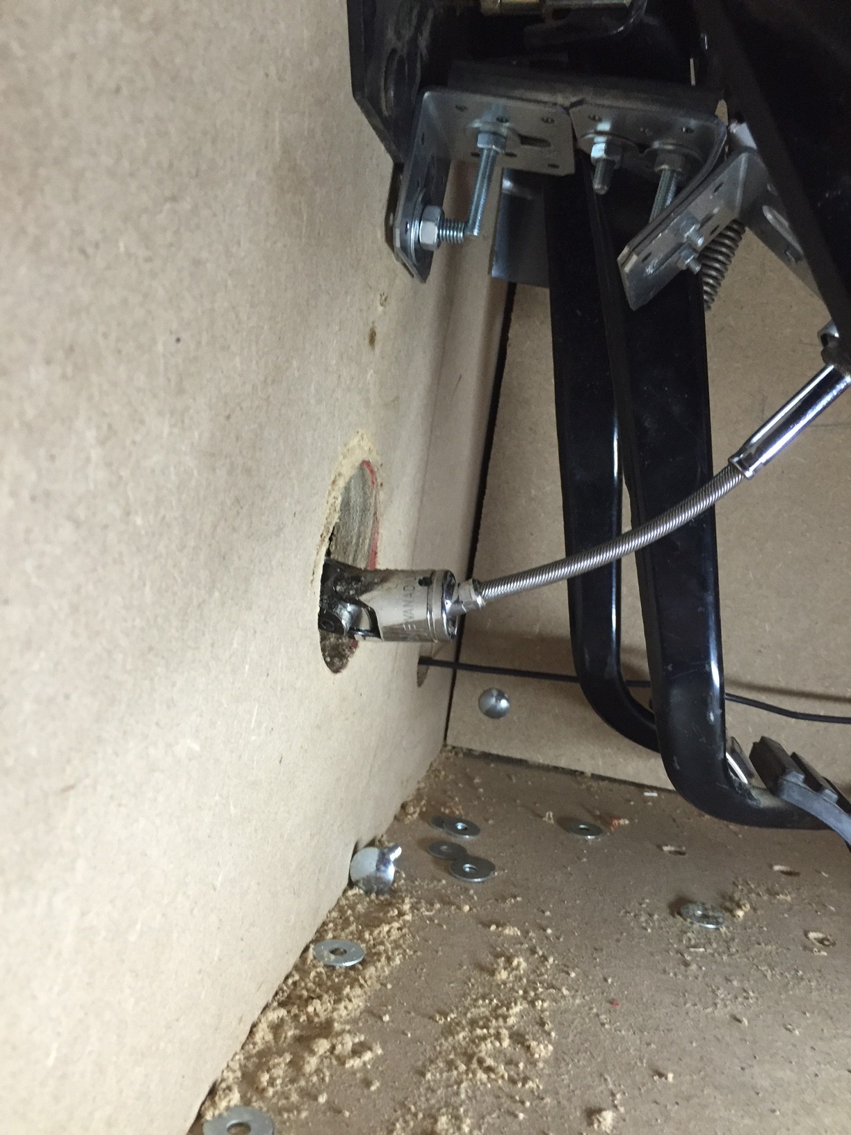
A flexible shaft is connected to the Logitech Driving Force GT Pro. THe bracket made in white is used to hold the steering axle in possition while making less noise than iron-to-iron. We might try some bearings later but they are hard to get and need to be alligned perfect in order to work.
![]()
Picture below:
A Toolbox u-joint was fixed on a metal bar to the Logitech Racing Wheel.
The flexible shaft was made from an old screwdriver with flexible shaft.
![]()
-
ACC / EDC Cruise Control Final!
02/22/2016 at 18:42 • 0 commentsProgress!
Parts Required:
1x Arduino Leonardo
1x 220 ohm resistor
Arduino IDE Code:
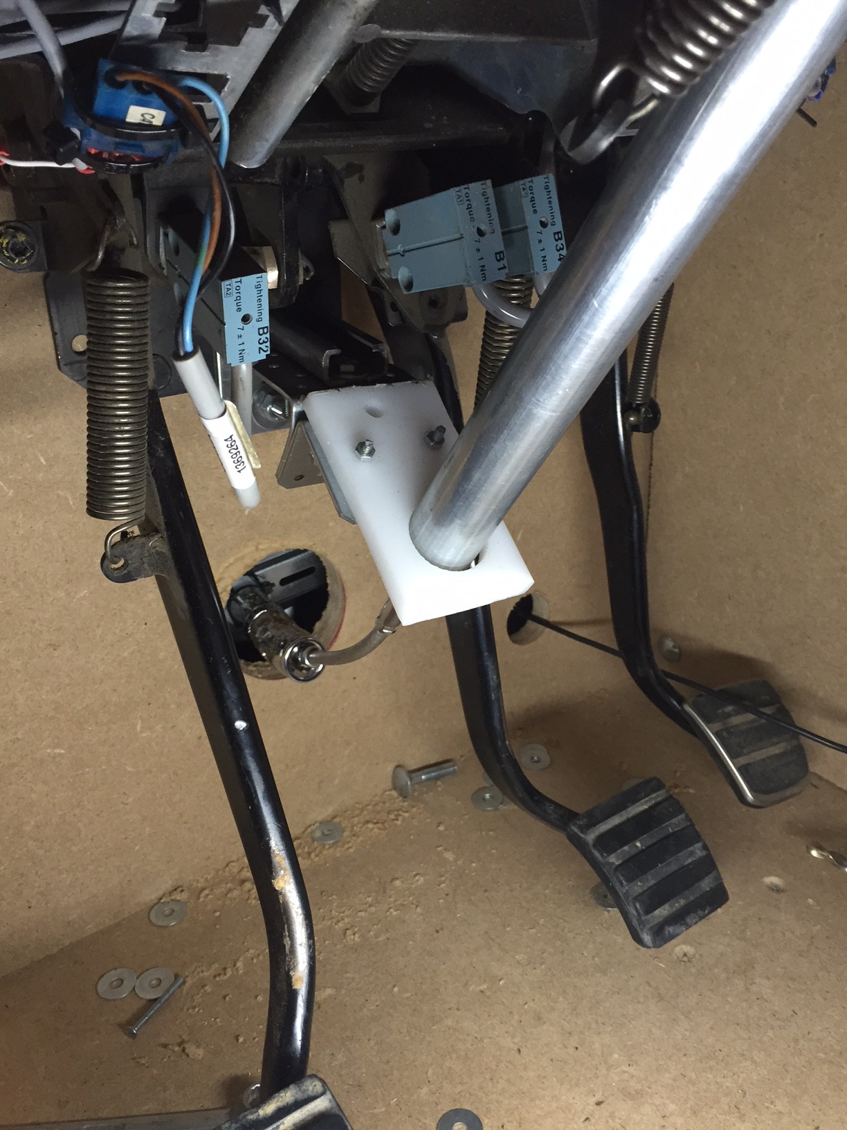
//Copyright Jeroen van der Velden 2018
//Released under by-nc-sa Non-Commercial Share Alike
//https://hackaday.io/project/8448

#include "Keyboard.h"
int lockpin = 13;
bool oldstate=false;
bool debugmode=false;
bool keystate=false;
char outchar=' ';
const int acctrip = 200;
const int restrip = 400;
const int rettrip = 600;
const int onlimit = 700;
const int offlimit = 890;
void setup() {
  pinMode(lockpin,INPUT_PULLUP); //no need for a pullup.
  // open the serial port
  Serial.begin(9600);
}

void loop() {
  int analogValue = analogRead(A0);
  debugmode=digitalRead(lockpin);
  if (debugmode==false)
    Keyboard.begin();
   else
    Keyboard.end();
  if (analogValue>offlimit)
    keystate=false;
    else keystate=true;
  if (oldstate != keystate)
     {oldstate=keystate;
      if (debugmode==false)
       Keyboard.write('c');
       else
       Serial.println ('c');
     }

  if ((analogValue <= onlimit)&&(analogValue>=acctrip))
   {if (analogValue>rettrip) outchar='8';
      else if (analogValue >restrip) outchar='7';
       else if (analogValue>acctrip) outchar='9';

    if (debugmode==false)
      Keyboard.write(outchar);
      else
      {Serial.print(outchar);
       Serial.print("  ");
       Serial.println(analogValue);
       };
    }
    //analogvalue in keyscan limit
      else
      {Serial.print("No char ");
      Serial.println(analogValue);
      }

    delay(150);
}
How to wire:
Connect the White and Black/Purple wire to the Arduino. White goes to GND and Black/Purple goes to the 220 Ohm Resistor.
From the resistor, go to 5v
Between the Black/Purple wire from the lever and the 220 Ohm resistor go to A0 (Analog input 0).
![]()
![]()
![]()
![]()
-
ACC / EDC Cruise Control Part 3
02/21/2016 at 12:11 • 0 commentsI made a video for the progress on the Cruise Control. Unfortunately its not finished yet, I still need to find the right code.
Code:
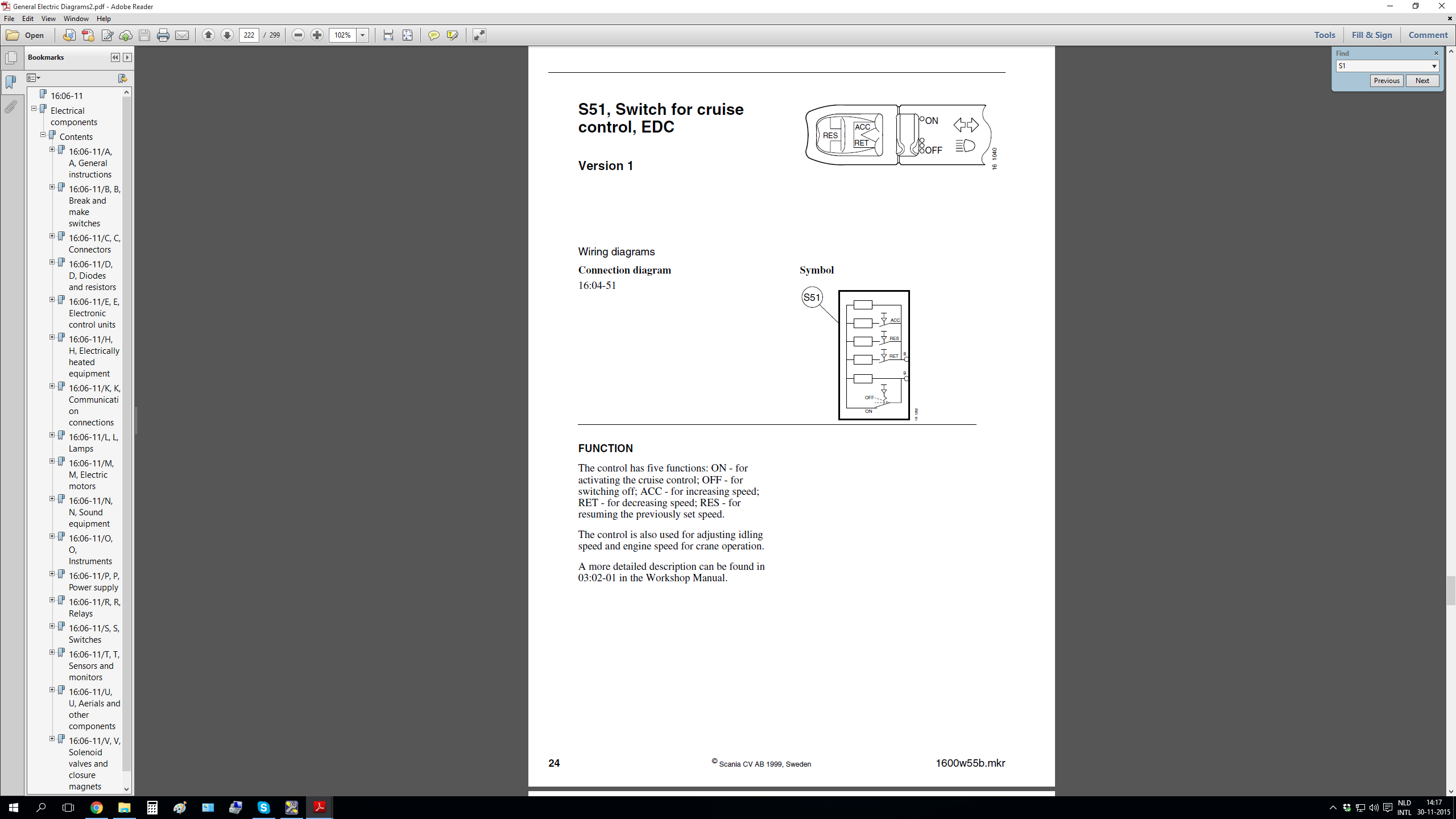
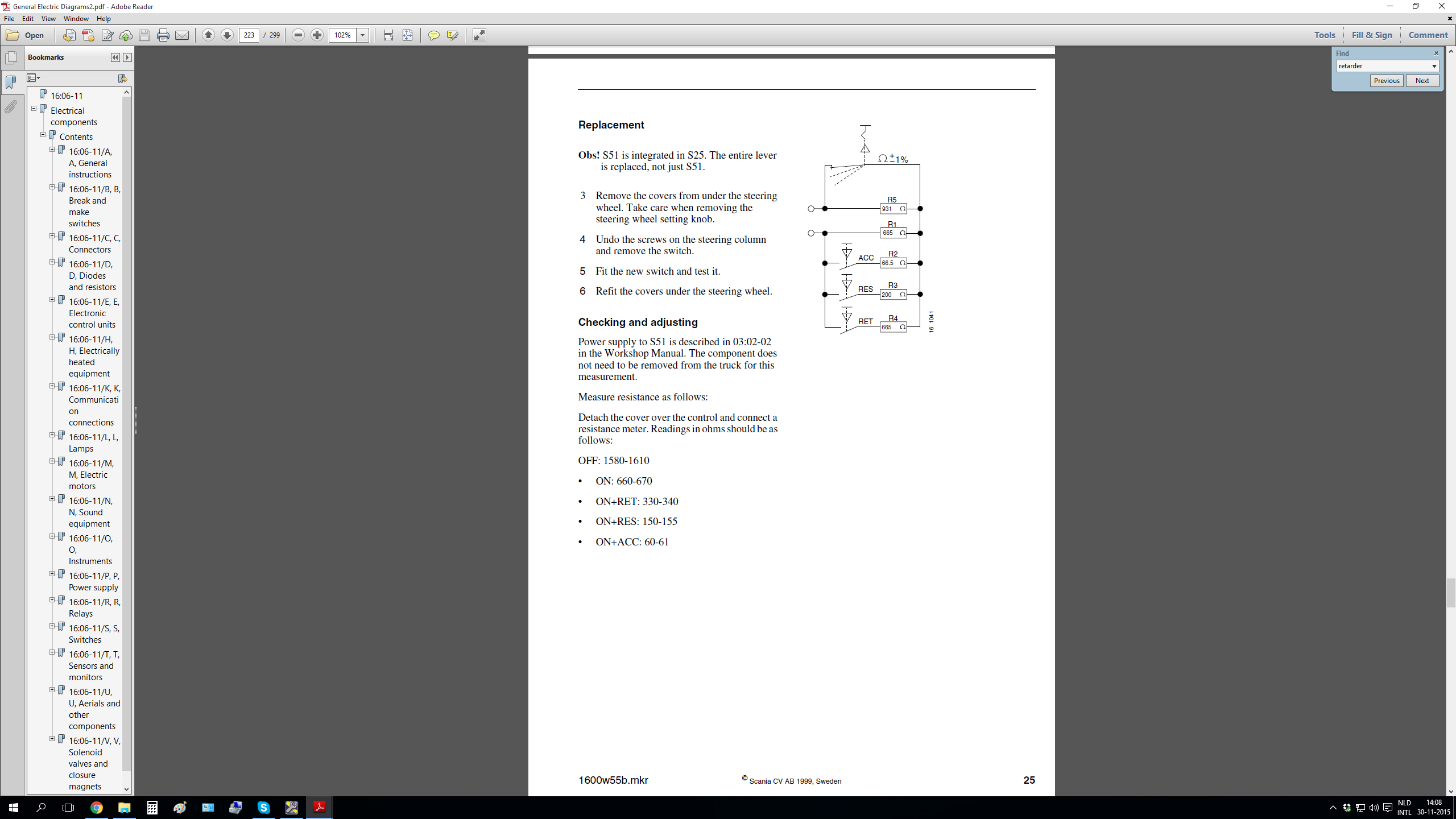
// Arduino Leonardo Rev3.0
// This code is for all Scania 4-Series
// ACC HID control for ETS2
void setup() {
  // initialize serial communication at 9600 bits per second:
  Serial.begin(9600);
}

// the loop routine runs over and over again forever:
void loop() {
  // read the input on analog pin 0:
  int analogValue = analogRead(A0);
  // print out the value you read:
  Serial.println(analogValue);
  delay(100);        // delay in between reads for stability
  if (analogValue > 870 && analogValue < 890) // read the analogue input into variable analogValue
  {
   //ACC is in the OFF Pos
   Serial.print("ACC OFF");
   delay(1);
  }
  else
  if (analogValue > 950 && analogValue < 965)
  {
   //ACC is in the ON Pos
   Serial.print("ACC ON");
   delay(1);
  }
   else
   if (analogValue > 985 && analogValue < 995)
  {
   //ACC is in the ON Pos and RET is Pressed
   Serial.print("ACC ON+RET");
   delay(1);
  }
  else
  if (analogValue > 1000 && analogValue < 1011)
  {
   //ACC is in the ON Pos and RES is Pressed
   Serial.print("ACC ON+RES");
   delay(1);
  }
   else
   if (analogValue > 1012 && analogValue < 1025)
  {
   //ACC is in the ON Pos and ACC is Pressed
   Serial.print("ACC ON+ACC");
   delay(1);
  }
}

// Jeroen van der Velden
// https://hackaday.io/project/8448-real-dashboard-truck-simulator
What I need:I have 3 switches:
1: Acc (Cruise Control Accelerate speed)
2: Ret (Cruise Control Retrieve speed)
3: Res (Cruise Control Resume from last speed)I have one toggle Switch:
Cruisecontrol ON/OFF
I want the ON/OFF to toggle a keyboard character "c" when used.
I want button 1 to send a "7"
I want button 2 to send an "8"
I want button 3 to send a "9"The code should pause after each change (no loop). The 10k Restistor is a pull-up resistor for debounce.
There is an Arduino Ohm meter tutorial so that might be a start.![]()
![]()
-
Steer Part 1
02/20/2016 at 19:07 • 0 commentsWe made a start on the Steer. Its not the final solution but for now it seems to do the job very well!
We used a Logitech Driving Force GT 900 degrees FFB USB Wheel. In ETS2 900 degrees gives a 1:1 ratio. My dad made a disk on the wheel and in the center he connected a universal joint from an old tool box. We cut off the steering shaft to and put in a pipe. We haven't tested it yet but it feels and looks clean and just perfect for the beginning.
![]()
Picture Below:
The gold colored pipe is the original Scania Shaft.
![]()
Picture Below:
A rusty cheap universal joint was used, I will test it and if it suits our need I will buy a High Quality U-Joint and replace it.
![]()
Keep following, a Youtube Video will be made soon!
-
Wiring Part 1
02/10/2016 at 13:32 • 0 commentsPicture Below:
This will be the 12C display (behind glass once finished) for the OptiCruise.
![]()
Picture Below:
All wiring goes to Phoenix Contacts (picture is just an illustration).
![]()
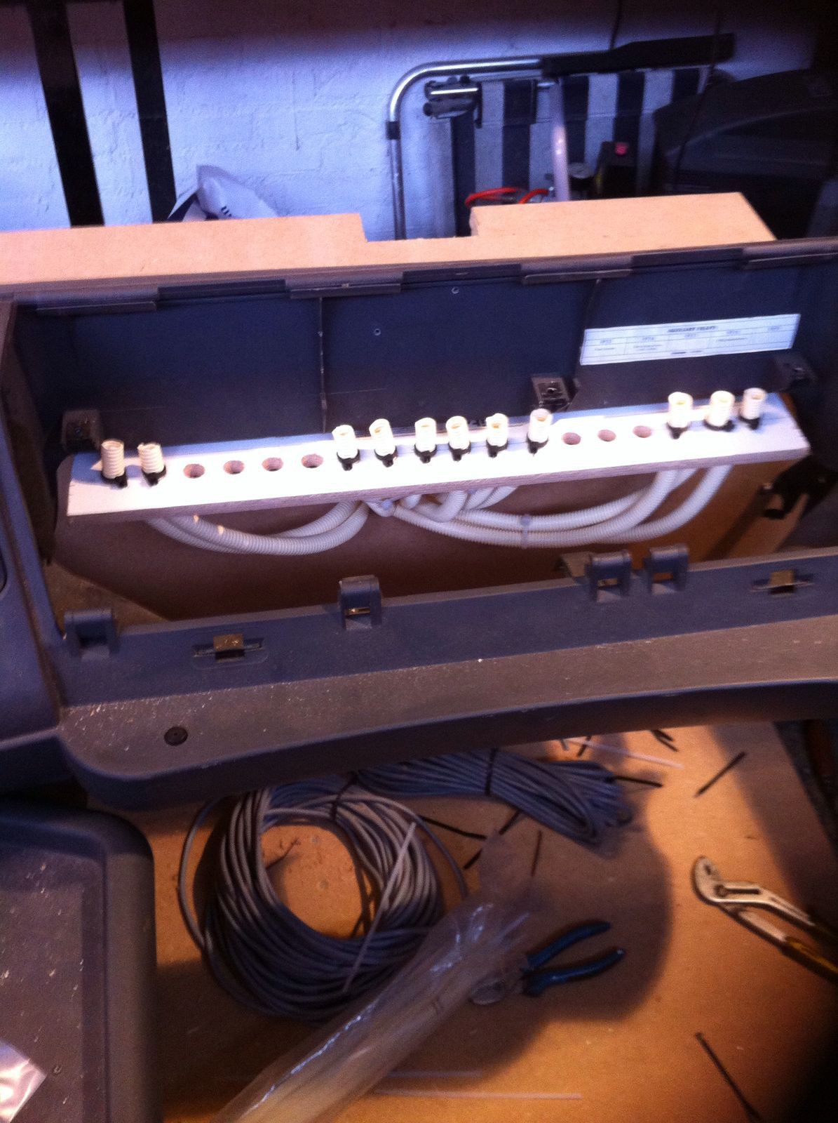
All wires sits in pipes to prevent trouble. Once the Dashboard is finished it will be hard to get everywhere so that`s why I use pipes.
![]()
Picture Below:
More pipes!
![]()
Picture Below:
More Pipes!
![]()
-
The wooden frame Part 2
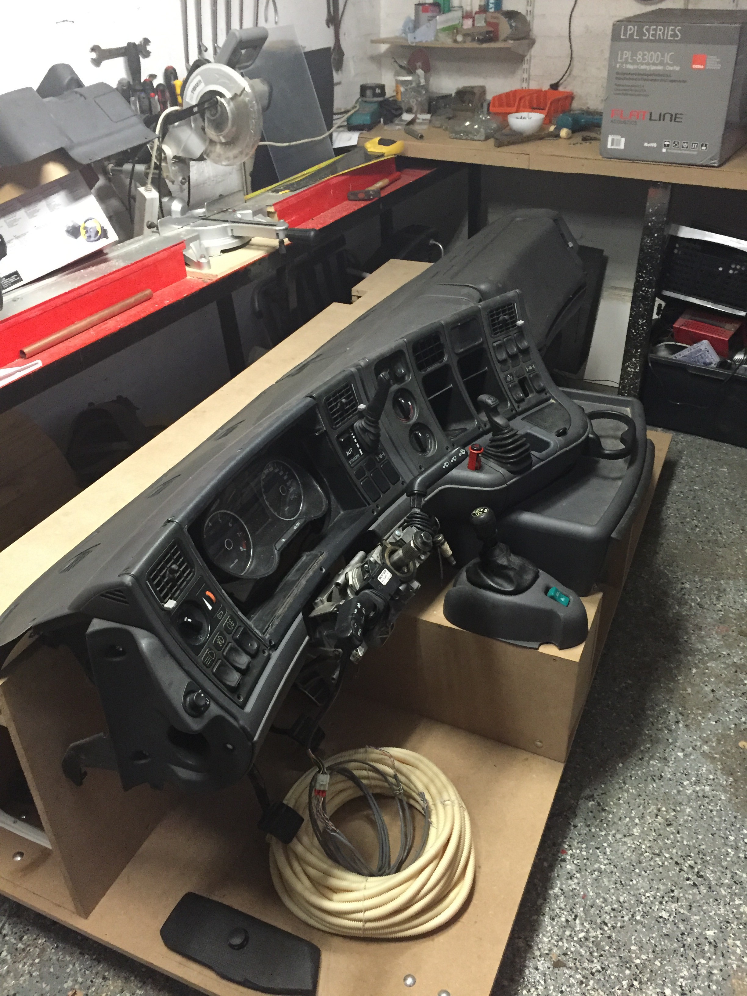
02/01/2016 at 12:29 • 0 commentsMore Pictures:
![]()
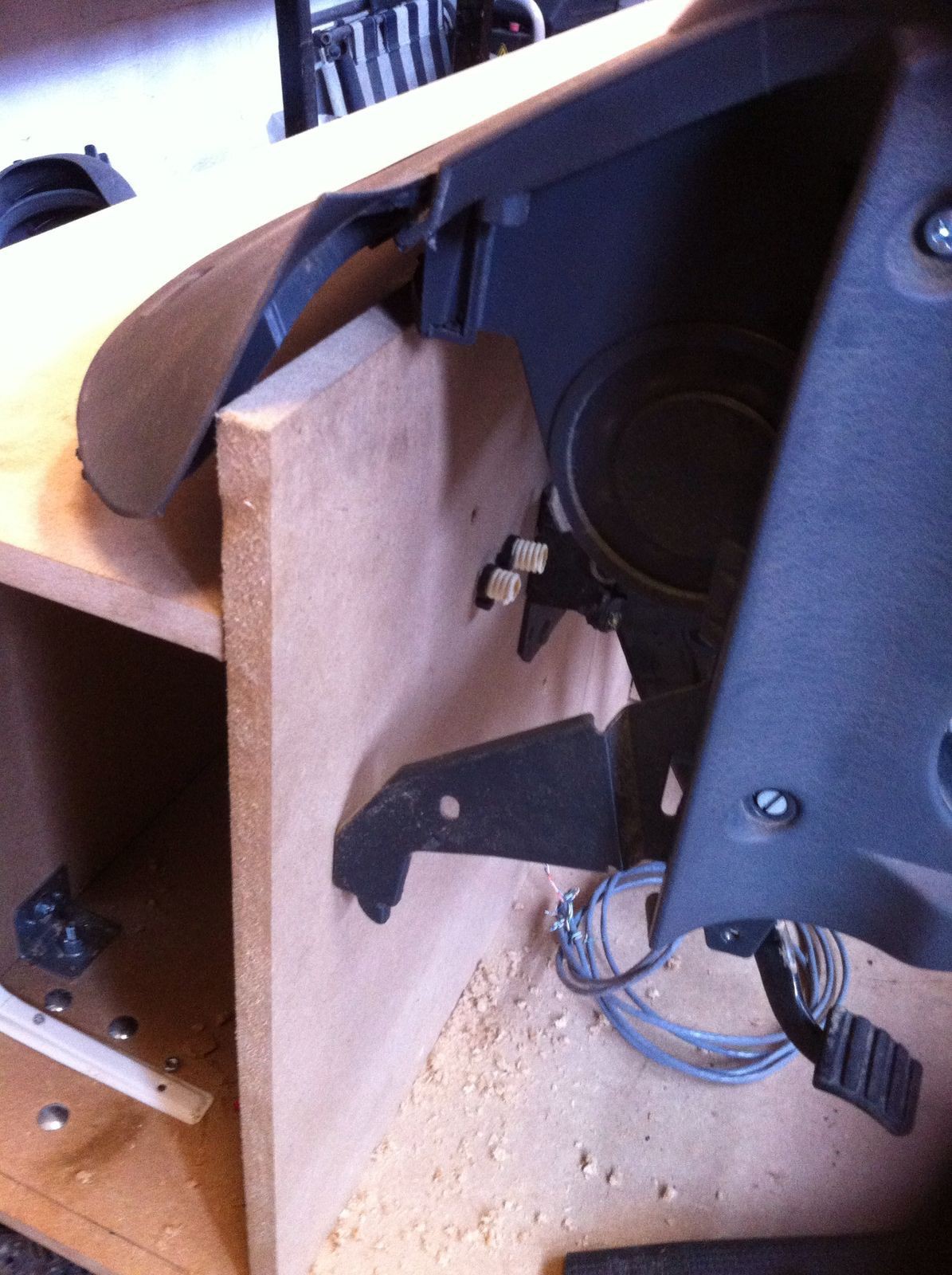
Picture below:
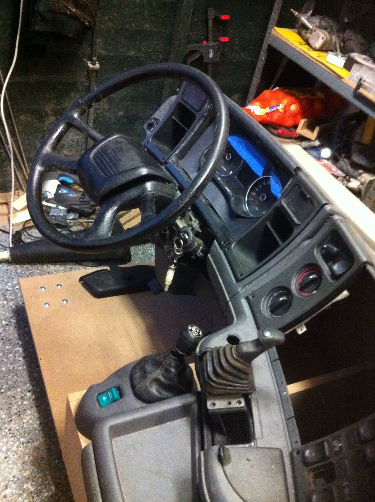
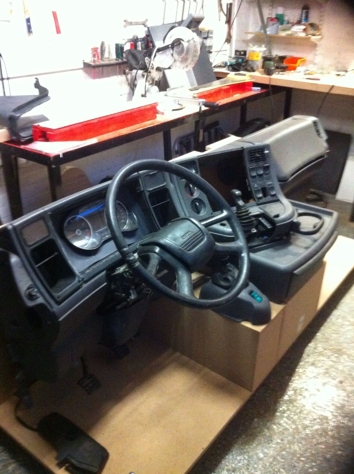
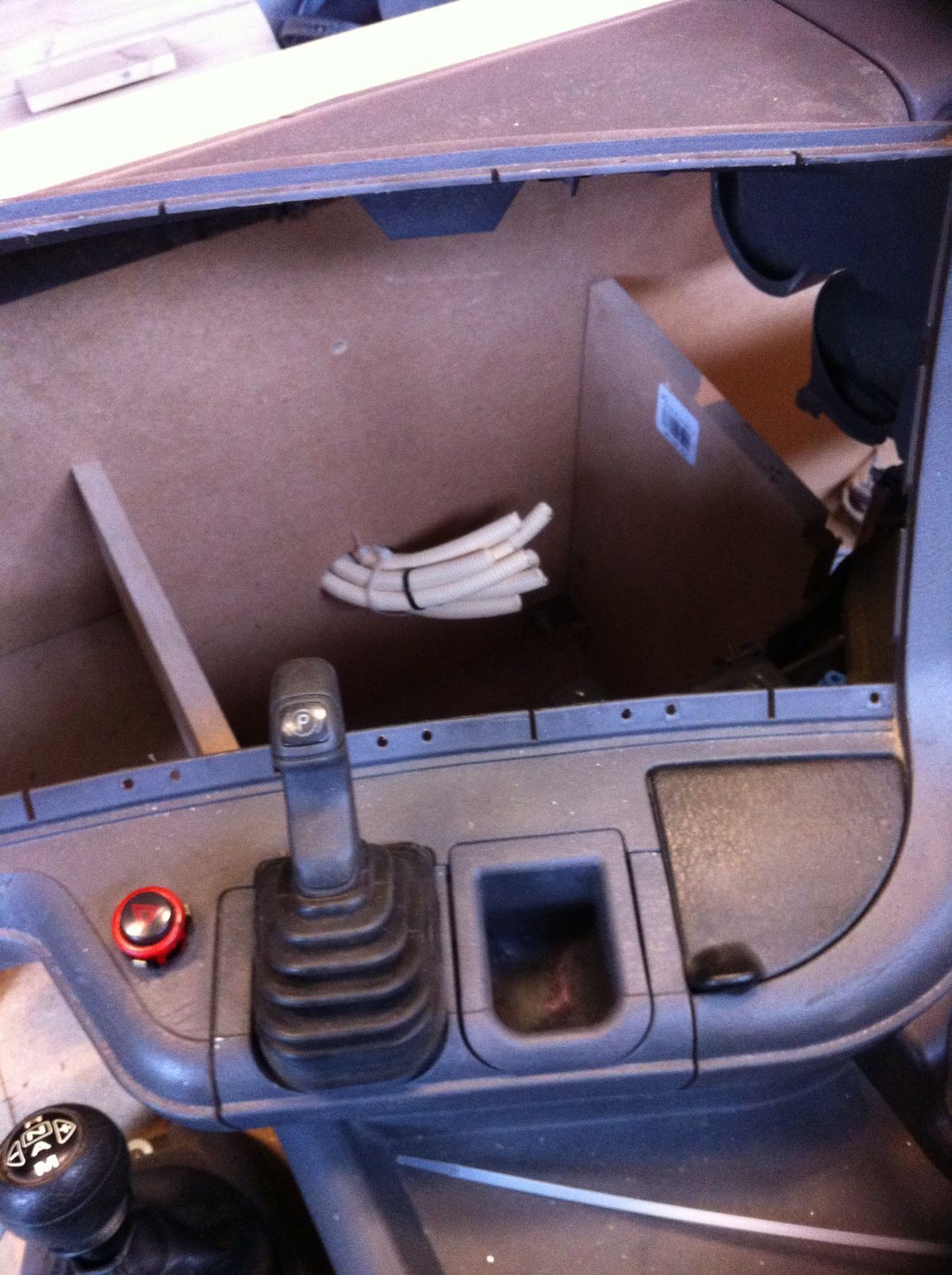
We made a small console for the Scania Opticruise gear shifter. We added the parking brake lever and VW Polo 6R Cockpit on a mounting bracket.
Also the Engine (Exhaust) Brake foor pedal is installed.
![]() Picture below:
Picture below:The Steering Wheel will be one of the most challenging items in this build. It so big and heavy that it would destroy a plastic racing wheel in seconds. So I`m working on a 900 degree Rotation and torque Limiter and Auto Center solution (more details soon).
![]()
![]()
Picture below:
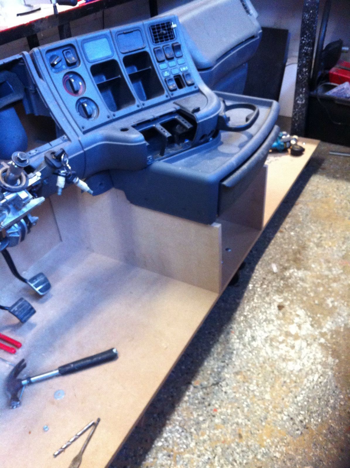
A tough part, the center console with drawer! This piece took nearly 48 hours to build, measure and fit.
![]()
Real Scania Truck Home Simulator
The Scrapyard and Arduino make a great combination!


 Picture below: