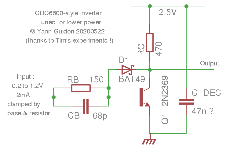
In his log Pushing RTL to <2 ns Propagation Delay, Tim alluded that a combination of base capacitor and base-collector diode could reach 2ns of transition time per inverter.
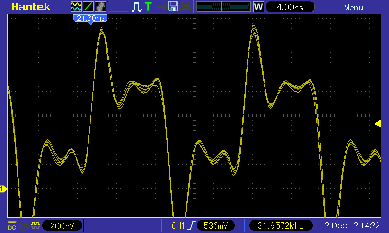
Well, @Tim, it wasn't that hard after all ;-) How about 1.73ns at only 5V ?

OK it's ugly (bad baaaad probing) and the CDC levels are pretty much destroyed...
But it's FAST and even more POWER EFFICIENT !
I get 32MHz at 5.2V and only 77mA, or 44mW per gate, a 4.5× improvement compared to Tim's 200 mW :-)
What's my secret ? Not much, it's explained in the previous logs ;-)
- ample capacitor decoupling
- low Rb (150 Ohms)
- finely chosen Cb (68 pF)
But this log has a newcomer : a Schottky diode. Spoiler alert : I didn't pay much attention, I found 2 reels of SMB and SMA-packaged low voltage diodes in my drawers. I don't even remember where/how/when/why I obtained them but here they are !

This version uses a ROHM RB751V-40 Schottky barrier diode in a tiny tiny package (almost 0603). It's limited to 20mA which matches well because the higher the current, the larger the junction, the more capacitance...
I also have MBR0520 diodes but the higher current rating potentially increases the capacitance, which would create more problems.
The 2N2369A is prevented from "switching hard", which has a welcome effect : less current is drawn ! At 1V the circuit sips only 3mA instead of 6mA... By 2V the difference is mostly erased, though, but at low voltages, that circuit is crazy efficient :-)

Impressive !
Here is the raw data for the summary graphics :
1     6  8.292    9.653    3  12.461
1.1   8  9.191   10.900    5  14.344
1.2  10  9.942   11.955    7  15.976
1.3  11  10.576  12.861    8  17.374
1.4  13  11.140  13.663   10  18.648
1.5  15  11.609  14.363   12  19.720
1.6  16  12.001  14.961   14  20.700
1.7  18  12.344  15.517   16  21.507
1.8  19  12.636  16.029   17  22.351
1.9  21  12.867  16.480   19  23.084
2    23  13.053  16.916   20  23.754
2.1  24  13.182  17.265   22  24.290
2.2  26  13.286  17.634   24  24.875
2.3  28  13.343  17.959   25  25.428
2.4  30  13.364  18.268   27  25.951
2.5  31  13.354  18.559   29  26.436
2.6  32  13.317  18.818   31  26.875
2.7  34  13.253  19.076   32  27.297
2.8  36  13.170  19.307   34  27.702
2.9  38  13.068  19.531   36  28.077
3    40  12.952  19.749   38  28.432
3.1  41  12.826  19.949   40  28.756
3.2  42  12.689  20.140   41  29.063
3.3  44  12.552  20.311   43  29.335
3.4  46  12.408  20.472   45  29.583
3.5  48  12.253  20.630   47  29.832
3.6  49  12.097  20.779   48  30.050
3.7  51  11.938  20.921   50  30.260
3.8  53  11.729  21.060   52  30.467
3.9  55  11.580  21.182   54  30.645
4    56  11.426  21.296   56  30.820
4.1   n   n      21.400   57  30.978
4.2   n   n      21.500   59  31.126
4.3   n   n      21.590   61  31.265
4.4   n   n      21.681   63  31.384
4.5   n   n      21.766   65  31.507
4.6   n   n      21.851   66  31.619
4.7   n   n      21.933   68  31.722
4.8   n   n      22.010   70  31.824
4.9   n   n      22.077   72  31.918
5     n   n      22.144   73  31.997
And the gnuplot commands :
set xlabel 'V'
set ylabel 'MHz'
set y2label 'mA'
set xr [1:5]
set yr [6:36]
set y2r [0:90]
set key right bottom
set y2tics 3
plot \
 "ringo9v2_0-68pf-RB751.dat" using 1:2 axes x1y2 title             "0pF current in  mA" w points pt 7, \
 "ringo9v2_0-68pf-RB751.dat" using 1:3           title           "0pF frequency in MHz" w lines, \
 "ringo9v2_0-68pf-RB751.dat" using 1:4           title          "66pF frequency in MHz" w lines, \
 "ringo9v2_0-68pf-RB751.dat" using 1:5 axes x1y2 title "Schottly+66pF  current  in  mA" w lines, \
 "ringo9v2_0-68pf-RB751.dat" using 1:6           title "Schottly+66pF frequency in MHz" w lines
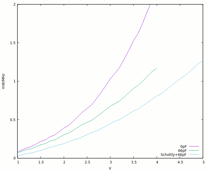
From there we can also plot the power/frequency curves with the following script :
set key right bottom
set xlabel 'V'
set xr [1:5]
set yr [0:2]
set ylabel 'mW/MHz'
plot "ringo9v2_0-68pf-RB751.dat" using 1:(($2*$1/$3))/9  title  "0pF" w lines, \
     "ringo9v2_0-68pf-RB751.dat" using 1:(($2*$1/$4))/9  title "66pF" w lines, \
     "ringo9v2_0-68pf-RB751.dat" using 1:(($5*$1/$6))/9  title "Schottly+66pF" w lines
The result is self-explanatory :-)

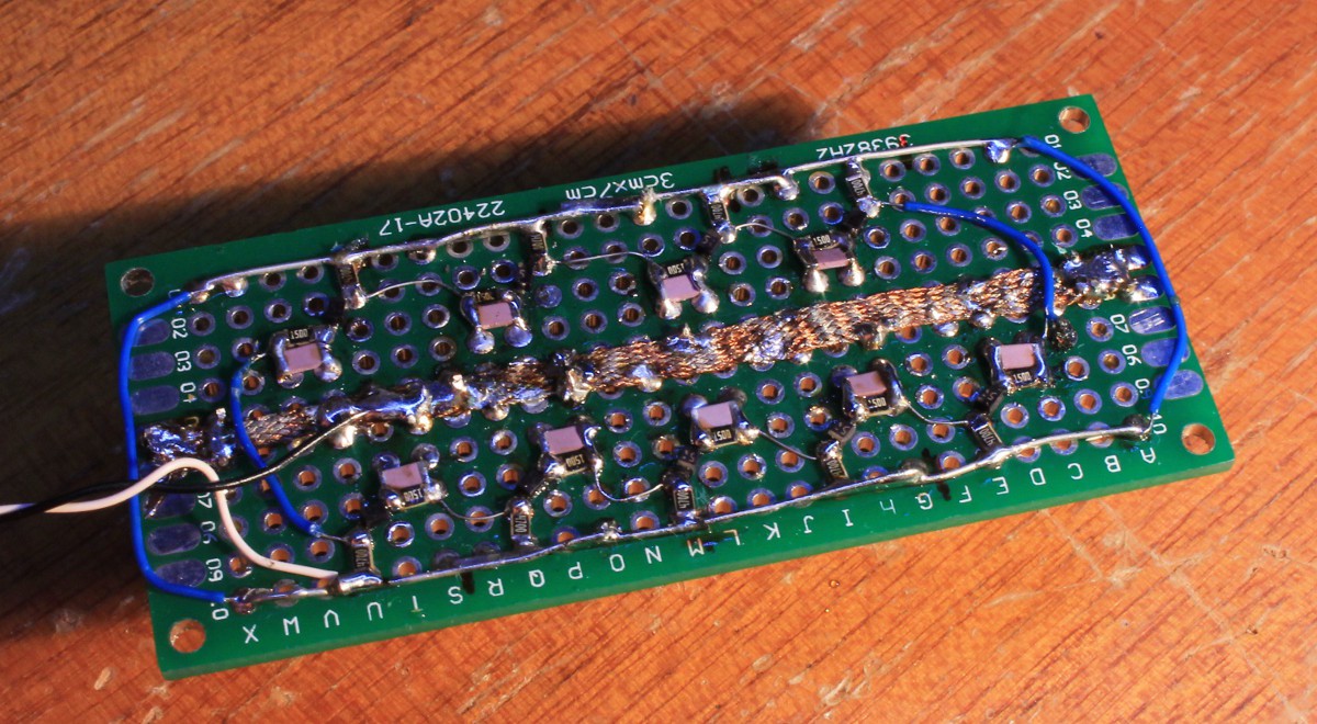
These curves were measured on this simple board :


What else is there to say ?
It's not the end of the adventure, of course, because it's only a ring oscillator and the diodes have destroyed the saturating "CDC levels". A clean PCB would help too, but mostly the problems come from multiple inputs driven by one output.
Oh, one last word : the 2N2369 is very cool and easy to use when you understand a few tricks. But there is one design flaw : the can is connected to the collector, not the emitter :-( At least the SMD versions use plastic cases that don't create short circuit hazards.
 Yann Guidon / YGDES
Discussions
Become a Hackaday.io Member
Create an account to leave a comment. Already have an account? Log In.
Fastest I've measured was gold doped KSP10 with 1N4148 for Baker. Discreet BAT Schottky capacitance worse than recovery time, not same as transistor with integrated Schottky. Clamping pull-up to an intermediate rail also makes even faster. Old scopeshots somewhere I would have to dig for...
Are you sure? yes | no
Dig, please, dig !
Now, the KSP10s are somewhat more expensive than the 2N2369...
Are you sure? yes | no
Great results ! How would it be when the base resistor is zero ohms ? That would make it a DCTL circuit.
Are you sure? yes | no
yes but this works only when one transistor is driven.
Two base loads or more create "balancing" problems due to spec variations and the problem gets more acute as the fanout increases. So it's best to test with the base resistor, even when this is the only load, so the measurements are meaningful and represent real life conditions.
Are you sure? yes | no
Btw, the RINGO5 with parallel capacitor reached 2ns at 39mA/4V=160mW or 26 mW/gate. I should have put the voltage data into my log. Every 100ps improvement beyond that truely escalates power usage, though... It reaches 1.8ns at 6V/61mA
Are you sure? yes | no
With great power come great electricity bills...
Are you sure? yes | no
Now we're waiting for your power/speed curves of your #LED Coupled Logic (LCL) ;-)
Are you sure? yes | no
Coming in a couple of weeks. I am currently designing a PCB.
Are you sure? yes | no
@cpldcpu is a PCB required ? You could solder discrete parts to a proto board, I suppose.
Are you sure? yes | no
@Tim Any update on that front ?
Are you sure? yes | no
uhh.... what exactly? Looks like LCL was completed.
Are you sure? yes | no
@Tim
What about your RINGO5 ? is it logged somewhere I haven't seen ?
Your power/perf figures look interesting, as I try to beat your 26mW/gate with IBM's LVI :-)
Are you sure? yes | no
Its right here:
https://hackaday.io/project/176107/logs
Are you sure? yes | no
@Tim Oh I totally forgot about this one !
That was epic, indeed.
Are you sure? yes | no
Hi Yann, really cool results!
I am almost surprised that the Baker clamps works so well. I was under the impression that there are not mayn suitable Schottky diodes out there, but it looks like you found a fitting one.
Actually I wonder whether it could go even faster when increasing both Rb and Cb, because that would also reduce saturation charge without impacting switching current. I need to do some simulations.
Are you sure? yes | no
yes there is a lot of parameter combinations to experiment !
but the faster you run, the more careful decoupling will be critical...
Are you sure? yes | no