engunneer
-
Problem boards
08/20/2014 at 04:13 • 0 commentsMy next problem is going to be with boards like the Beaglebone Black and the Mojo FPGA boards. They have double row connectors for I/O along each edge.
To keep MakerMod host board sizes to a minimum, I've been using surface mount connectors for boards like the Arduino and having the Right angle female MakerMod headers reach over them to the edge of the board. This makes for a clean layout that is not much larger than the Arduino.
![]()
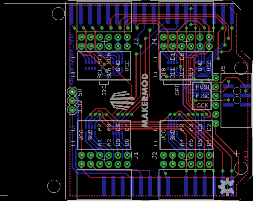
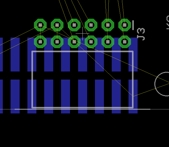
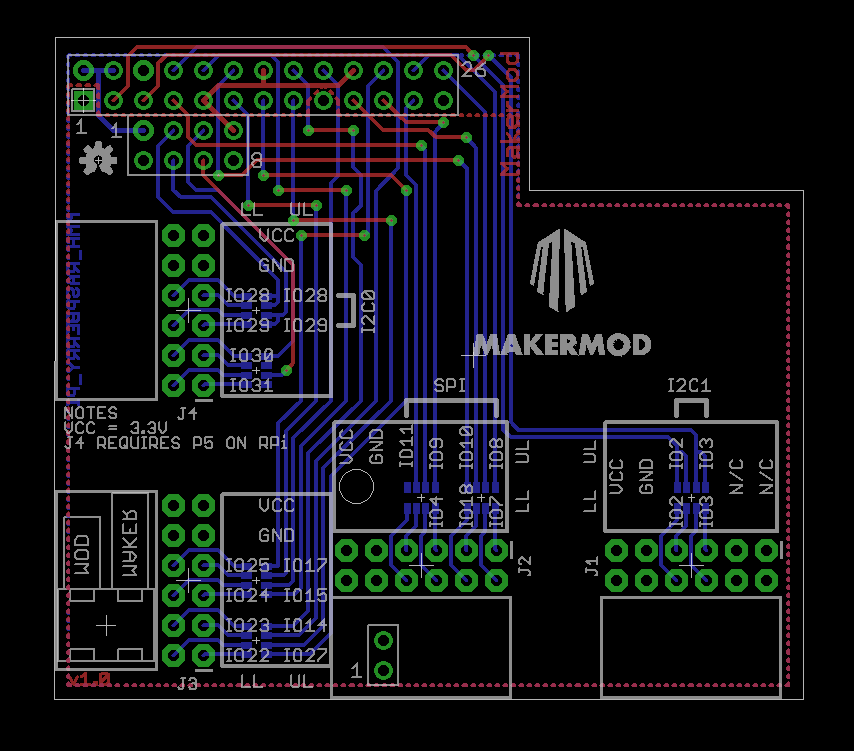
This runs into a problem with the double row headers as shown in this Mojo layout, where you can see that there is basically no place to put the MakerMod port that doesn't interfere with the SMD pins.
![]()
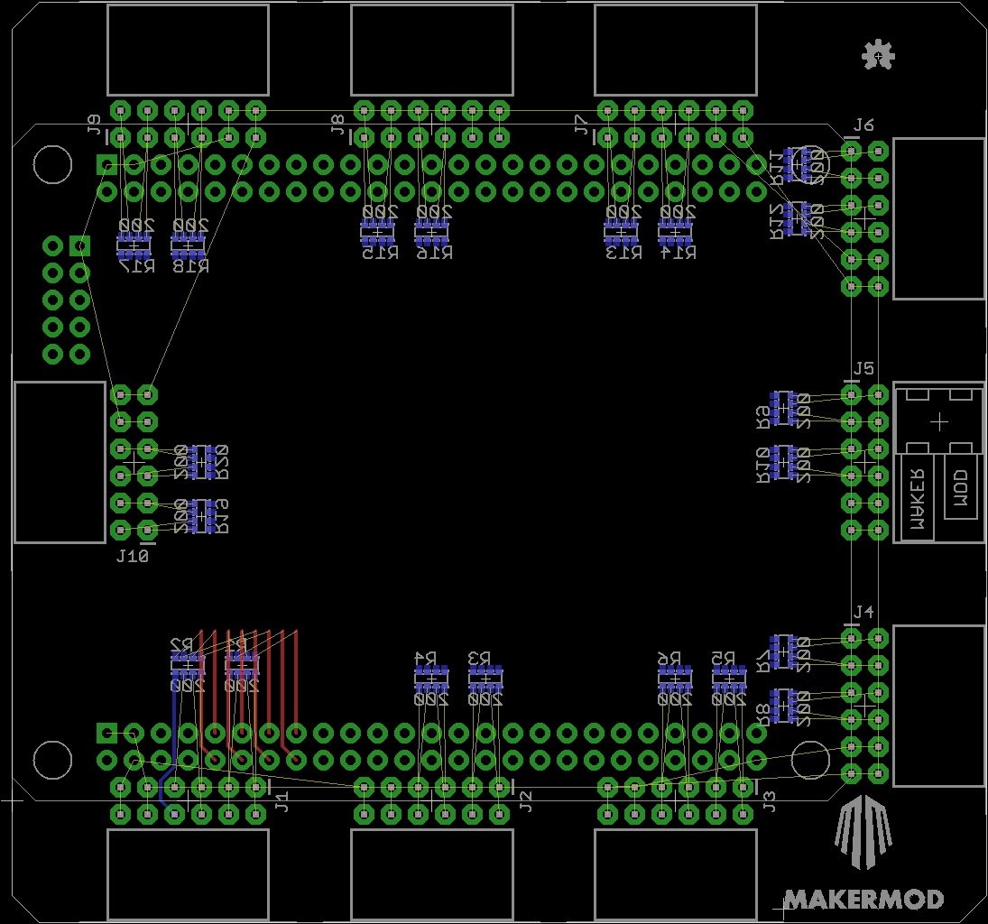
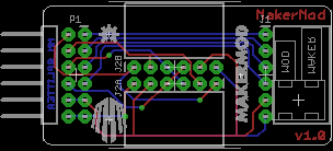
Instead, If I go with through hole headers to the Mojo, the MakerMod ports have to be outside the Mojo pins, to keep the MakerMod port flush with the face of the board. This is a lot larger, but I'm not seeing a great way to get around it.
![]()
Also, the Mojo has a LOT of I/O.
-
Next Boards
08/20/2014 at 03:43 • 0 commentsI've designed the next few boards for the project, but haven't ordered them yet. I've been focused on host boards and useful accessory boards lately, and will get back to modules once a few hosts are set up.
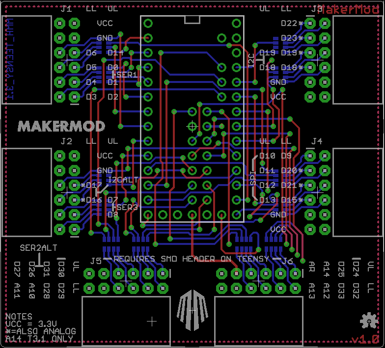
I've finished routing the Teensy 3.1 carrier board:
![]()
The idea with the Teensy is that the two ports on the bottom edge of the board use the SMD extra header pins from the bottom of the Teensy, and the other 4 ports use the traditional pins from the outer edge.
For the Raspberry Pi Model B, there is a similar extra port. J4 requires the 8 pin header P5 from the Raspberry Pi to function.
![]()
In the accessory department, I have a Splitter, which will convert a dual row header into two single row headers. The second header can be pointed either up or down depending on the part placement.
![]()
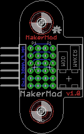
I also have a part I am calling a Flange. The flange is a pass through port with mounting holes
![]()
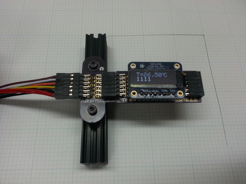
The mounting holes are 30mm apart and sized for M3. The idea is to allow remote mounting of buttons and LCDs on a project (Think about a 3D printer's front control panel). I actually have ordered some of these. Here is an example of an OLED screen mounted on a piece of Openbeam. I'm not entirely happy that a standoff is needed to protect the pins, but it works for now.
![]()
This also goes with the MakerMod cable, which is a 6 or 12 pin Male to Female cable. I'm using Pololu pre-crimped wires for now to make the cables. I also have made a 12 pin to dual 6 pin splitter.
-
First test project
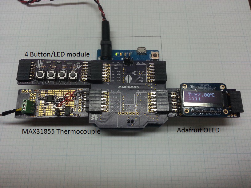
08/18/2014 at 04:12 • 0 comments![]()
Using the OSHW schematic from adafruit for her MAX31855 Thermocouple breakout board, an SPI OLED display, and the MM4IO v1.0 module, I put together a small Arduino project to test the usability of the system and test out the first prototypes.
I was ab;e to use the libraries for both Adafruit products with no modifications. One of the many goals of this project is to use existing OSHW modules from other fantastic electronics vendors and simply repackage them into the common format. This means I don't need to write new libraries for every platform.
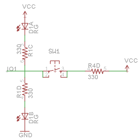
Doing this project I did figure out the IO module just wasn't going to work the way I wanted it to. Here's the schematic for a single channel of the v1.0 board.
![]()
The idea was that a pin in input mode on a host board would keep both LEDs off until you pressed the button, sending VCC to the host and turning on the green LED for that channel. An output from the host would light the red LED for logic low and the green LED for logic high. (In the schematic I am using a dual package red/green LED. Red is the A LED and green is the B LED) The 1.0 version had enough current to lightly illuminate both LEDs at 5V VCC, and logic inputs to the host just didn't function. I also had the wrong footprint on the LED, so the later versions update this as well.
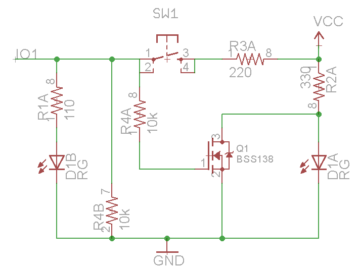
Here's the new v1.2 board schematic to show the difference.
![]()
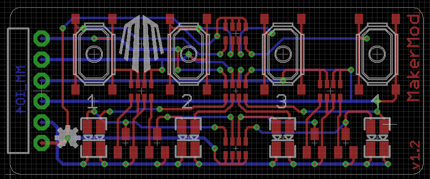
Version 1.2 has a transistor for the red LED, and attempts to balance the resistor values, but the green will be brighter than red in output mode. It works on the bench (See the end of the overview video), and I am happy with the layout.
![]()
-
Breadboard and Arduino First Revisions!
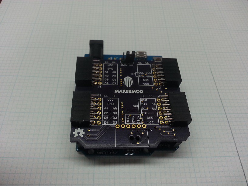
08/17/2014 at 03:24 • 0 commentsMy second order of boards was for the Arduino Host Adapter and the Breadboard adapter.
![]()
The Arduino shield ended up having a few minor problems. The SMD pins on the bottom had pads that were too small and actually faced the wrong way, too. I did some creative soldering and got it to work.
I also had a few swapped labels on my pins. This was my first shot at documenting the port designations in the silk. I'm trying to keep all components on the bottom, except for the connectors.
The last thing I wasn't really happy with was the 3.3V/5V jumper for VCC select. I think I want all future Hosts to be 3.3V only, and 5V controllers will need level conversion. This is tough, because it moves cost from the modules to the host for 5V hosts. This will also be a problem on Analog breakouts. Still not sure exactly what I want to do here.
I also got to test the I/O board from the last post. It definitely didn't work the way I expected, and I also had a few footprint issues, so I have a new version drawn up that will be in the next PCB order. I'm pretty happy with the layout. I am finicky about how I want to run my traces, and this layout appeals to me. I may decide there must be a via in the OSHW logo from now on.
![]()
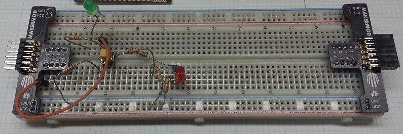
One of the goals of the project is to still allow fast prototyping using breadboards and the soldered proto modules, so I designed an adapter for my solderless breadboard to make it into a large MakerMod module.
![]()
The neat thing here is that both ends actually use the same PCB. Flip it one way to make a male port, and the other way for the female. VCC and GND are routed to the power rails on the side of the breadboard. The circuit shown here is actually a single channel of v1.2 of the Button and LED board, with some series resistors making the values I wanted.
-
First Prototypes
08/07/2014 at 02:11 • 0 commentsI got the first prototype boards in for MakerMod a few weeks ago. First up are some of the boards for designing circuits on:
PTH Proto has both a male and female dual row MakerMod connector. The central two rows are VCC and GND rails, and the outer holes are connected like a mini breadboard in 1x3 columns.
![]()
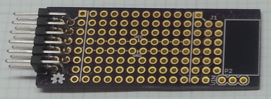
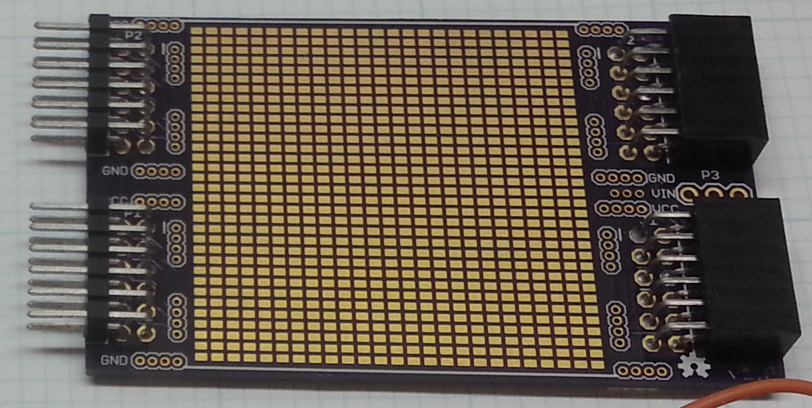
The SMD Proto comes in two flavors, narrow and wide. The Narrow board is the same as the PTH Proto, but has a grid of SMD pads instead. These pads are not connected together, and are in a 0.05" x 0.065" grid. VCC and GND are provided in some 0.05" pitch vias on the corners of the board. The back is pretty much blank. I might put a ground plane there in the future and drop some vias down to it inside the SMD field.
![]()
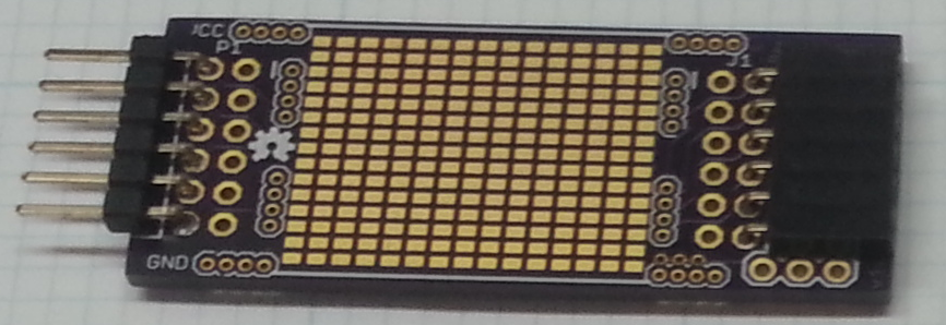
The wide SMD Proto board is basically two narrow boards in one, providing a larger build area.
![]()
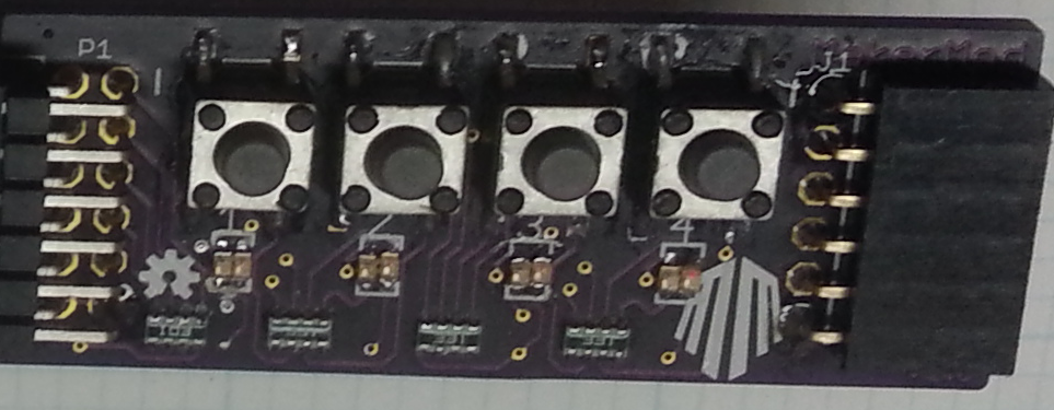
The last board in this OSHPark order is the 4 button I/O module. Each button has a green/red LED and a button that connects the IO pin to VCC. When the I/O is driven as a low output, the LED will be lit red. when it is driven with a high output, or is an input with the button pressed, the LED is green.
![]()
MakerMod System
A common connection format for hardware peripherals for multiple development platforms.