Close
0%
0%

wESP32: Wired ESP32 with Ethernet and PoE

A low cost ESP32 core board with Ethernet and PoE for convenient "single cable" deployments

Public Chat
Similar projects worth following
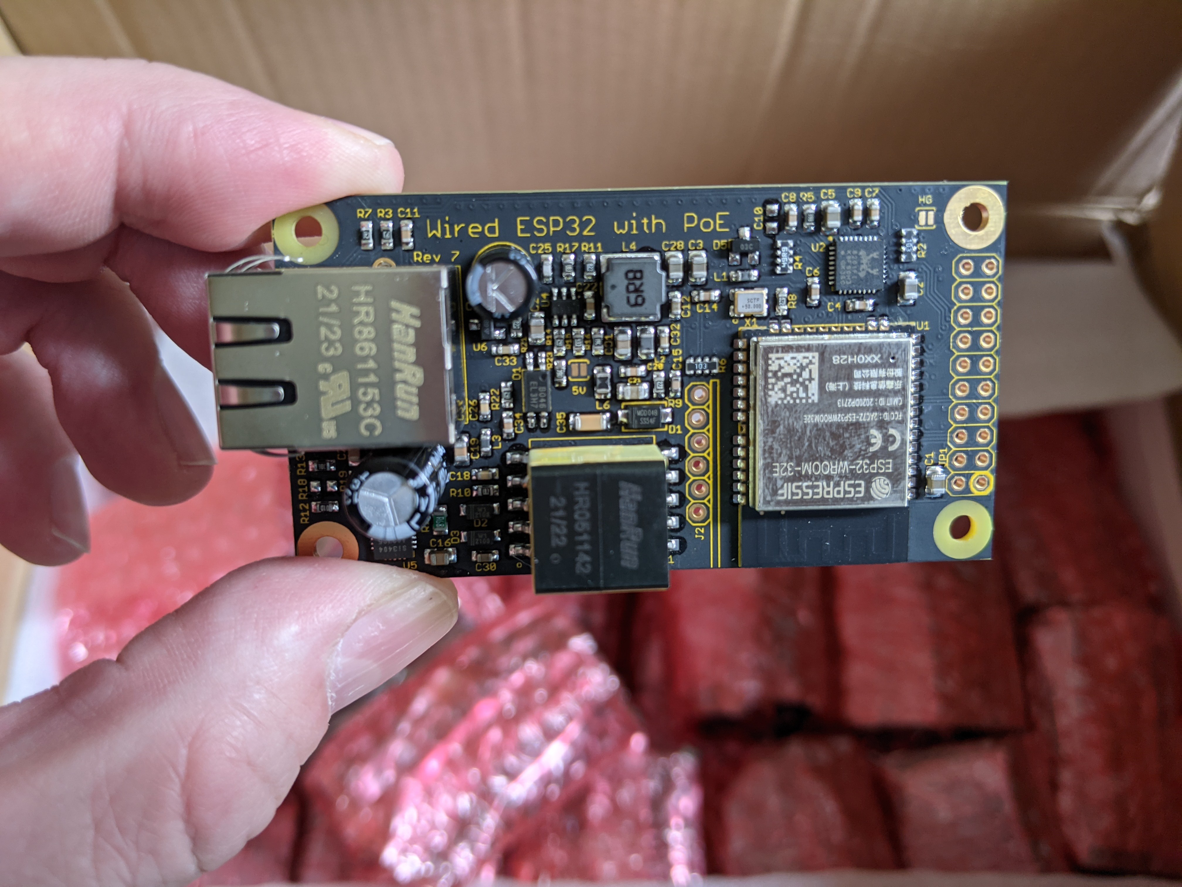
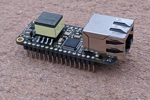
The ESP32 is very popular among makers as the brains for various projects. Usually it is connected to the internet with WiFi, but an often overlooked feature of the ESP32 is that it also contains an Ethernet MAC. This project aims to create a hacker friendly ESP32 + Ethernet + PoE core board to make it very easy to apply the power of the ESP32 in new areas such as home automation, factory automation, smart buildings and data centers, where the use PoE provides major advantages in installation and maintenance.

Due to the high power consumption of WiFi, most ESP32 based systems already require wired power. Since you already need a wire, why not provide power and connectivity through a single wire and bypass deployment hassles associated with WiFi credentials and RF performance in hard-to-reach locations?

Plus the high power available with PoE makes it possible to not only make ESP32 based sensor nodes, but to create smart network-connected actuators as well!

I just completed an application-specific ESP32 based PoE board for a customer, and it got me thinking: how much interest would there be in a generic ESP32 PoE core board?

By using PoE, a single cable provides power as well as connectivity, easing deployment headaches for large installations.  PoE can provide up to 12.95 W to a load while PoE+ specifies up to 25.50 W.  Plenty for an ESP32 which takes only a watt or so, making it possible to power other loads.  PoE capable network switches and injectors are also becoming quite common and have come down in price as well.

The nice thing about the ESP32 is that it's low cost and powerful, and provides WiFi and Bluetooth in addition to Ethernet.  So even if a deployment would be mostly Ethernet and PoE based, it would still be possible to connect a node with WiFi powered from another source if necessary.  Or it could be set up as an access point for other WiFi or Bluetooth LE based sensors.

While it would be nice to support as much power as possible, previous experience has taught me that high power opens all sorts of cans of worms related to heat dissipation and EMI.  So it seems prudent to not start at the highest power levels possible.  Some potential users also showed interest in compact, very low power systems, but there are plenty who were excited about the idea of having a decent amount of power available.  So I decided to take the middle road and do a 12.95W PoE class 3 design to start with.

The ability to use local power instead of PoE is a nice feature, but also adds complexity and cost.  The problem is that PoE uses 48V nominal to reduce wiring losses, but commonly available wall warts use lower voltages for safety.  Supporting both would require the circuit to support for a wide input voltage range making things more complex.

So I settled for the following solutions: local power can provided either by adding a PoE injector, or through the (optional) USB port.  Of course, from the USB port, only 5V will be available.

Talking about the USB port, several potential users expressed the opinion to not burden every board with something that would likely only be used during once during programming and never again after that.  I agree, so I made the USB programming/terminal port an optional module.

Other than those concerns, I want this module to be fully isolated (to prevent issues with long cabling), full featured (Ethernet, WiFi, Bluetooth LE, many ESP32 pins exposed), low cost and small.

wESP32-7-CCBYSA.pdf

Schematic of wESP32 rev 7 with RTL8201 Ethernet PHY

Adobe Portable Document Format - 43.26 kB - 01/14/2022 at 18:15

Preview

wESP32-3-mechanical.pdf

Mechanical drawing of the wESP32 rev 3

Adobe Portable Document Format - 88.38 kB - 01/07/2020 at 16:37

Preview

wESP32-Prog-1-Eagle.zip

Eagle CAD source files of the wESP32-Prog programming submodule

Zip Archive - 50.43 kB - 10/07/2019 at 14:41

Download

wESP32-Prog-1.pdf

Schematic of wESP32-Prog programming submodule

Adobe Portable Document Format - 19.49 kB - 10/07/2019 at 14:41

Preview

wESP32-3.pdf

Schematic of wESP32 rev 3 with PMS150C to manage PHY reset

Adobe Portable Document Format - 43.55 kB - 03/19/2019 at 23:10

Preview

View all 11 files

  • Revision 7 is available for sale!

    Patrick Van Oosterwijck09/30/2021 at 16:10 7 comments

    A little late posting here, but just a heads-up that revision 7 has arrived and is making its way to various distribution channels!

    New 4-layer PCB, much more decoupling capacitance on-board, RTL8201FI Ethernet Phy and now 16 MB of flash!

    Tindie: https://www.tindie.com/products/silicognition/wesp32/

    Mouser: https://www.mouser.com/ProductDetail/Silicognition/CS-WESP-04?qs=sGAEpiMZZMu3sxpa5v1qrriU3DaWTQdbHa4MxnML6FE%3D

    Amazon: https://www.amazon.com/Silicognition-wESP32-Isolated-Ethernet-802-3at/dp/B084RV91NQ/

    Note that the lead time shown on Mouser is bogus, they had 100 units shipped to them already.  Should ship much sooner than the lead time indicates.

  • Documentation update

    Patrick Van Oosterwijck09/13/2021 at 17:59 0 comments

    A quick heads-up that I finally found the time to update the wESP32.com website with new information related to the changes in revision 7 such as 16 MB of flash and RTL8201 Ethernet PHY.  The product brief has also been updated, make sure to check the code examples to see the changes you may need to make to your software for this revision!

  • Kingtop finished production

    Patrick Van Oosterwijck09/09/2021 at 16:30 0 comments

    A quick progress report.  MicroPython 1.17 dropped on September 2 2021 which meant that I finally had an officially released binary with support for the new wESP32 with 16 MB flash.

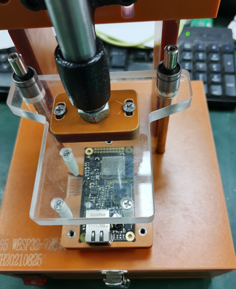
    To remove the biggest bottleneck in production called "me" from the equation as much as possible, I had my CM Kingtop build a fixture so they could program and test them, instead of me still having to do that with every board.  They built a nice fixture:

    Much better looking than my fixture hacked together from two perf boards. ;)  That worked, but hurt your hand when running too many boards.  Big improvement.

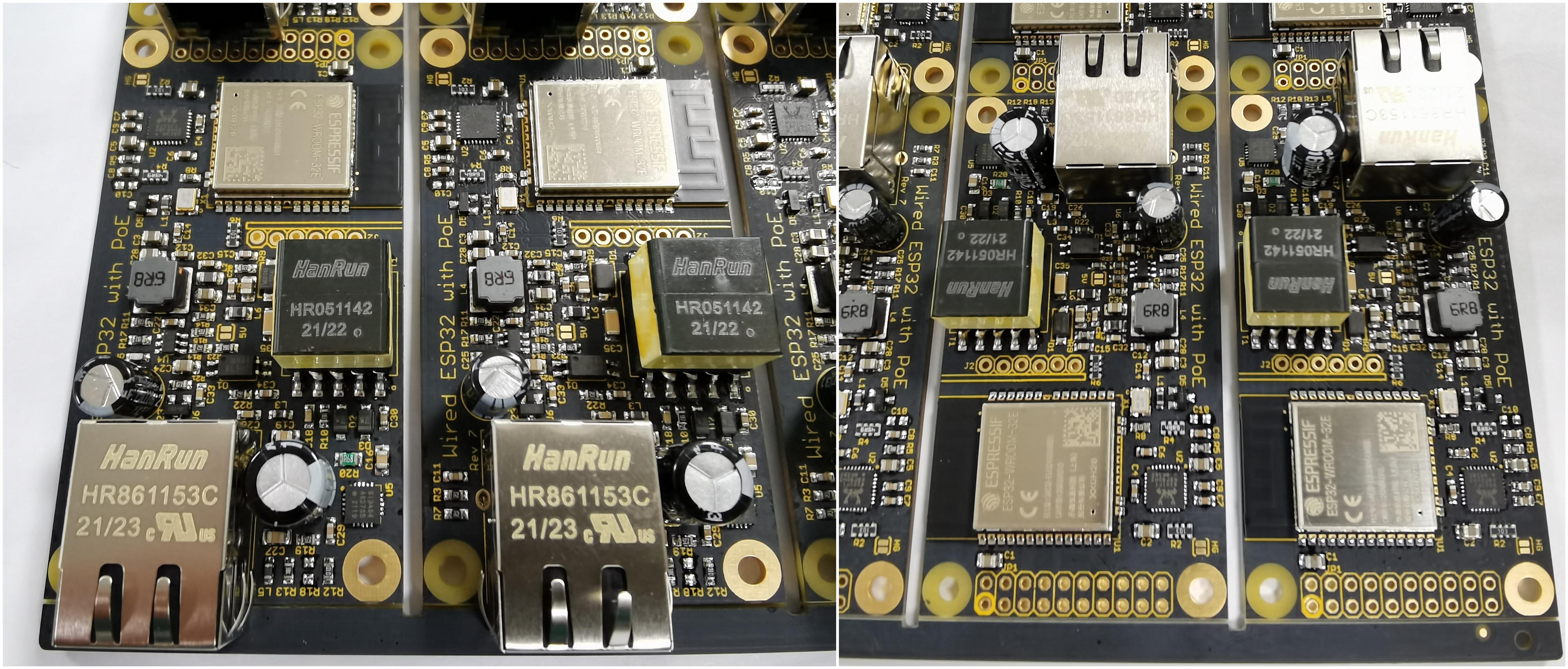
    Kingtop finished populating the through-hole parts and programmed and tested all boards:

    They reported two boards that failed on initial test, but they were able to correct the problem.  So an initial failure rate of 0.2%, and 0% after rework, that speaks very well to their build quality and processes.  Believe me, I've seen much much worse!

    They are ready to ship them now and it's still looking good for getting stock mid-September.

    Now I only have to harass Mouser some more to try and get them to send me a PO for the new part numbers generated for this revision, after begging for months already.  But why do something ahead of time when you can do it when it's too late, right? 🙄

  • Revision 7 production progress

    Patrick Van Oosterwijck08/20/2021 at 22:00 1 comment

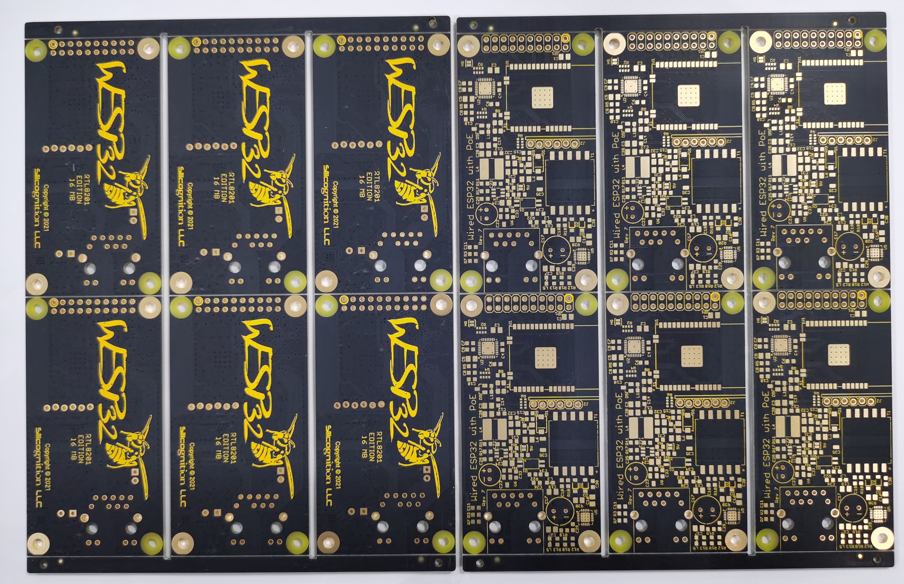
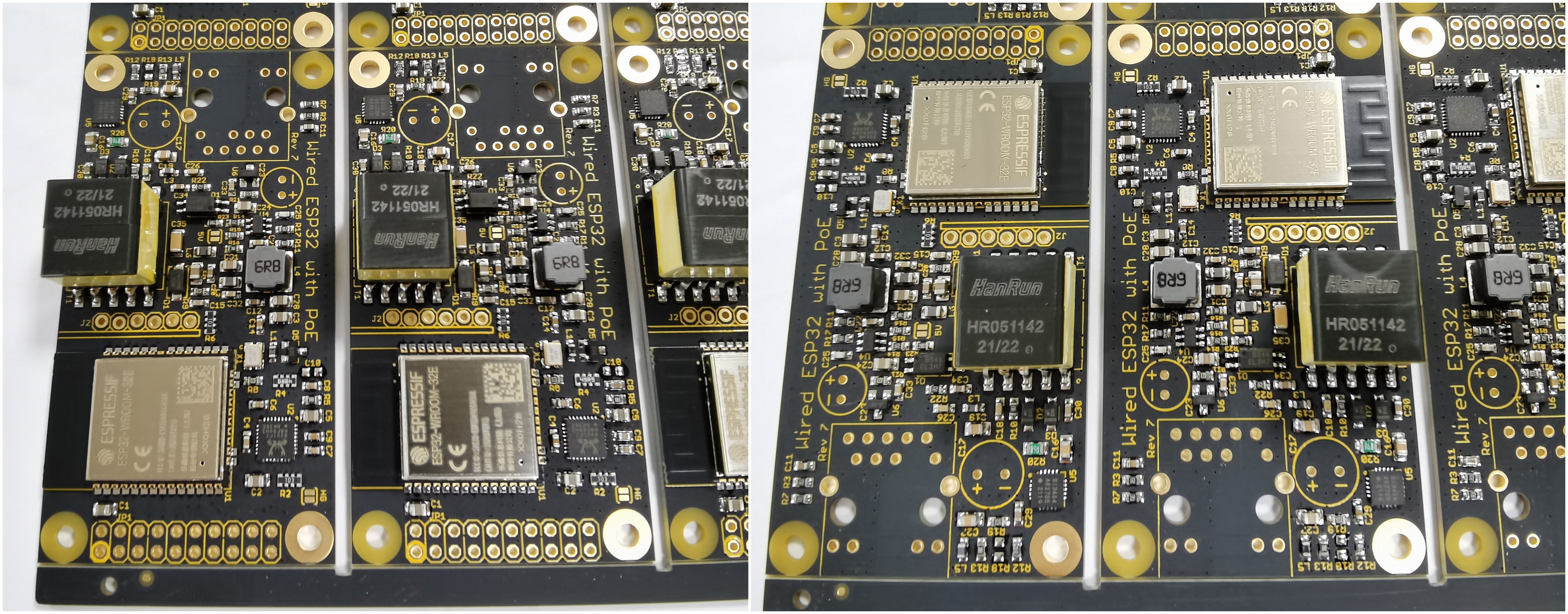
    After waiting for four months since I ordered them, Mouser finally shipped the SI3404A PoE chip to my CM, so they have started production.  I received this picture of the new PCBs:

    Looking good.  I think there shouldn't be confusion about which PHY this uses, since I have it in pretty big letters on the bottom.  Last night, I received this picture with surface mount components mounted:

    Nice progress!  You can see the new RTL8201FI Ethernet PHYs and the ESP32-WROOM-32E module with 16 MB of flash.

    Meanwhile, I have also managed to get a custom board config merged into upstream MicroPython so you can actually make use of all that flash memory!  Up till now, I used the generic ESP32 images but they are made to use only 4 MB of flash.  The flash memory will be partitioned with two nice 2.4 MB OTA partitions so we should be safe for a while as MicroPython keeps growing, and a nice 11 MB of flash will be available for the MicroPython file system!  I'm hoping that version 1.17 will be released soon so I can give an official release to my CM to program in to the boards.  As usual, the boards will also come with a custom boot.py file that will set up the LAN for you.  So if you use the built-in MicroPython, the change to a different PHY chip will be completely transparent.

    I also ran some more performance testing and compared performance of the old LAN7820AI with the new RTL8201FI using the latest IDF's ethernet iperf example.  It looks like the LAN8720AI is marginally faster with UDP, while the RTL8201FI is marginally faster with TCP.  Overall, performance seems to be just fine.  The following numbers are approximate:

    LAN8720AIRTL8201FI
    iperf UDP ESP32 serving
    88 Mbit/s
    83 Mbit/s
    iperf UDP ESP32 client
    61 Mbit/s
    60 Mbit/s
    iperf TCP ESP32 serving
    23 Mbit/s
    25 Mbit/s
    iperf TCP ESP32 client
    27 Mbit/s
    30 Mbit/s

  • Bye bye LAN8720AI, hello RTL8201FI

    Patrick Van Oosterwijck05/27/2021 at 22:49 3 comments

    It had come to my attention that some customers had problems that some of their boards would stop working.  When they returned them and I did a postmortem, it was always the LAN8720AI Ethernet PHY that had died.

    Eventually I was able to recreate a setup that would reliably kill the LAN8720AI.  If I had a wESP32 connected to a particular PoE switch, with the USB programmer connected to a particular laptop, the chip would die when plugging in the Ethernet jack.  So I set out to try and determine root cause and find a solution.

    Doing some measurements on what exactly happened when plugging in the Ethernet using a battery powered oscilloscope, I could see some spikes occur on the 3.3V supply and ground when the cable was plugged in.  My theory was that maybe the charges on the various EMI caps connecting primary to secondary in the PoE switch power supply, the laptop power supply and the wESP32 would redistribute on connection and cause ground bounce that would for a very short time expose the LAN8720AI to out of spec voltages.

    Now doing these kinds of measurements, you're never really sure about what you're seeing, what's real and what's just a measurement artifact.  So I wasn't really sure, but it was something to go after.  I would try to improve supply filtering, add TVSes for ESD protection on the supply and signal pairs, and add filtering in the ground connection between the EMI cap and the circuit ground.

    I first changed supply filter caps on an existing board.  I tried larger bulk caps, and smaller close-to-the-pin caps for better response to high frequency spikes.  Didn't help.  I ordered TVSes, and added one to the 3.3V supply and filtered analog PHY supply.  No difference.

    I decided to create a new, 4-layer board layout with footprint for ESD protection on the Ethernet differential pairs, the supply, and a differential filter that would including filtering ground spikes that might be coming through the PoE supply's EMI cap.  I went to 4-layer with a 3.3V power plane adjacent to GND through 0.1 mm prepreg to provide improved HF power supply filtering.

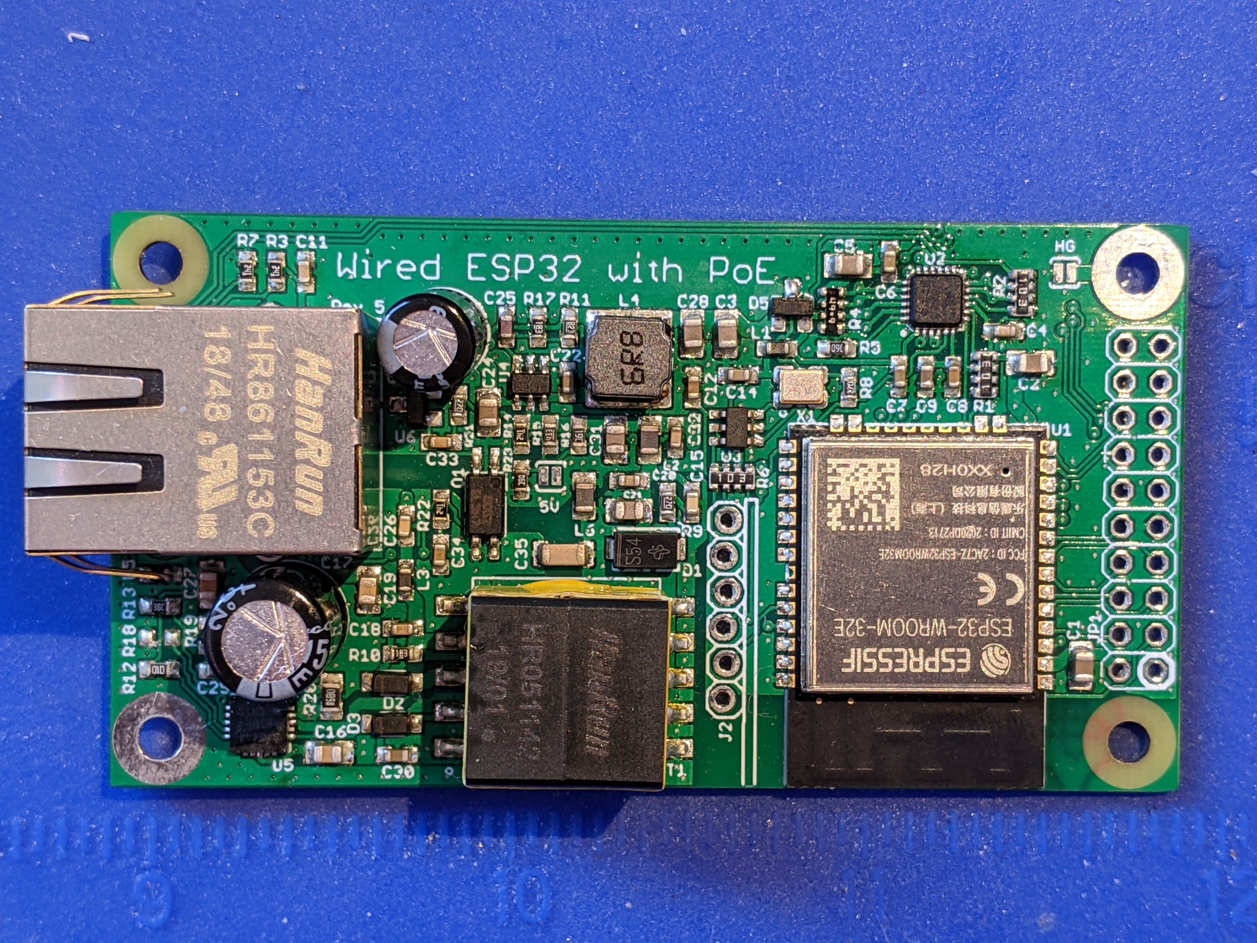
    Here's the prototype:

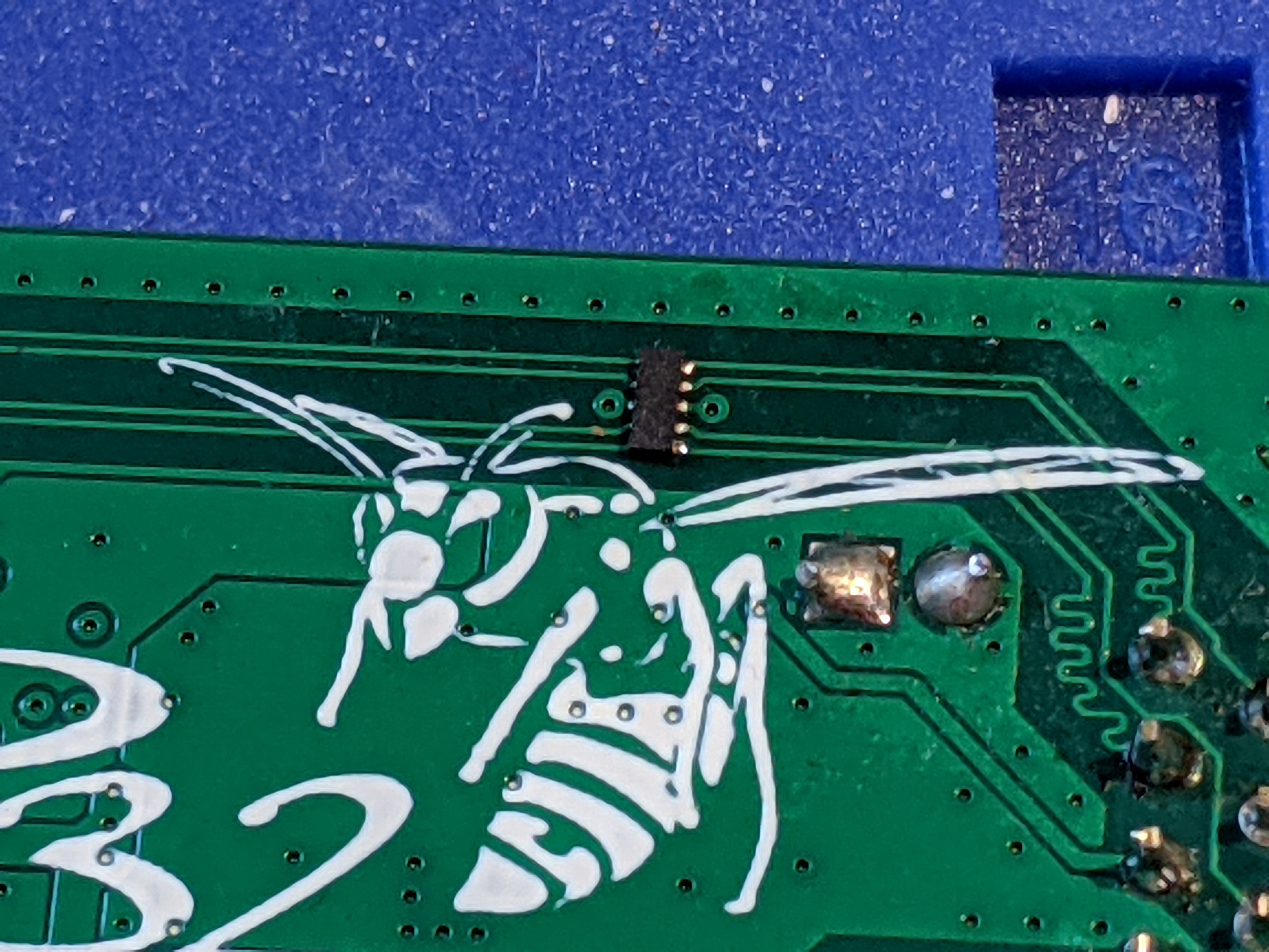
    Here's the ESD protection chip I added to the data pairs, the little chip above the wasp:

    Aaaaand it didn't help squat. 😠  The PHY died just the same as before.

    Now what?  Stock was running low, and I really would rather not make another 1000 potentially troublesome boards that might die in some setups.  My goal is for the wESP32 to be powerful and reliable, able to take whatever you can throw at it.  Dying when connected to certain equipment just won't do.  I've only had a few customers complain about it, usually in some situation where there's external power, so it doesn't seem to be a widespread problem.  But still, I don't find it acceptable.

    I did some investigating, and found that in the years since the wESP32 was first released, the ESP-IDF has come to support more PHY chips.  It looks like IDF 4.x added more options, and the ESP32 Arduino core also already supports them.  In the mean time, MicroPython has dropped the IDF 3.x based images that supported Ethernet, but support may be coming in the IDF 4.x based images.  So, this opened possibilities.  IDF, Arduino and MicroPython support are the most important for me, other software is likely to follow as it gets migrated from IDF 3.x to IDF 4.x.

    I had tried to avoid changing PHY chips because I don't like forcing customers to have to change their software.  It's only a change in the PHY definition, so it's minimal effort, but it's still a change that needs to be made.  I had considered it a last resort, but after all this effort and killing tons of chips while testing, I had to finally admit defeat in my efforts to stop the LAN8720AI from dying.  I had really tried hard, tried everything I could think of to protect the chip, to no avail.

    So I set out to create a prototype with the RTL8201FI...

    Read more »

  • Second production run

    Patrick Van Oosterwijck05/10/2019 at 18:36 4 comments

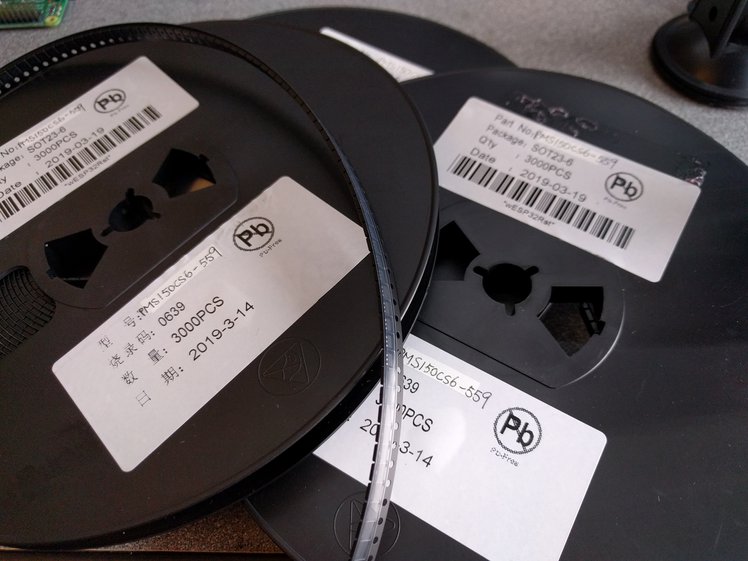
    "Silicognition" PMS150C-559

    As mentioned in the last update, I ordered factory programmed Padauk PMS150C-U06 chips from Sino-Mos to provide a reliable reset for the PHY chip on every board.

    I expected everything to be OK with them, but you never know 100% for sure if everything was understood correctly when dealing with China, until you actually have something in-hand. For one thing, I was relieved that they had indeed re-reeled them. It would have been a big bummer if I would have received a bag of loose SOT-23’s. :)
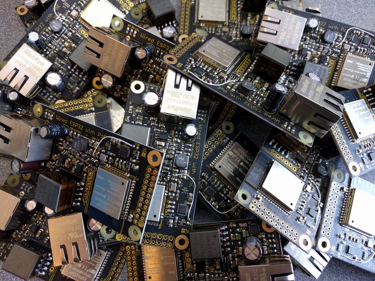
    Then I had to make sure they were indeed programmed. So I reworked another 12 boards from the first batch that didn’t initialize the PHY correctly with chips from one of these reels, and after rework they all work flawlessly!

    Getting these chips has actually been a smoother experience than I had expected. It’s kind of cool to now have a low-cost custom chip that does exactly what I want it to do, with its own partnumber and everything. PMS150C-559 is now forever an “ESP32 Ethernet PHY reset manager”. Maybe I should write a datasheet for it. :)
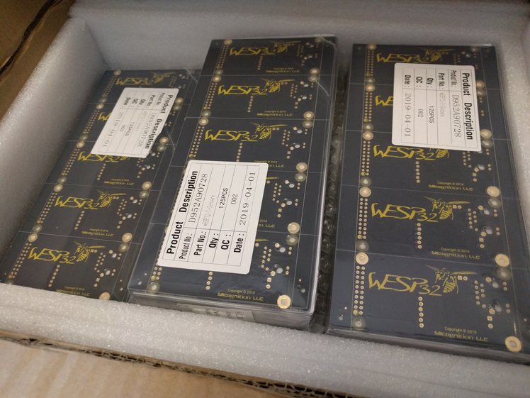
    Also, since I have 9,000 of them, I can definitely spare some if anyone is making their own ESP32 board with Ethernet and wants a canned solution to deal with the LAN8720A PHY reset. There’s an updated schematic that shows how the chip is used on the new wESP32 revision. So get in touch if you want to buy some.

    Rev 3 PCBs

    I took a little risk and ordered new PCB panels that use the PMS150C-559 before I had verified the factory programmed chips. But it had all been taking much longer than expected already and some backers have been wondering when they’d receive their reward, so I tried to recoup some time that way.

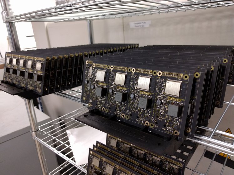
    Having everything in-house I made a kit to send to a CM I was going to try in Mexico.  That's when things started to go really sideways.
    The scourge that is customs

    The first customs issue I ran into: how to do the paperwork correctly. This was going into Mexico temporarily just to have it assembled and then it was coming right back to the US. I sought advice from the CM and a local export company, and yes, I received information on some generalities, but no one really gave me any concrete answers on what codes to use, exemptions to claim or checkboxes to tick. So after wasting almost a week waiting for guidance I gave up and shipped the box with the documentation as good as I could figure it. I marked the shipment with the AES 30.37(q) to indicate a temporary export that would be returned within a year. Whether that is correct or not I don’t know. Nobody had told me what to do and it seemed the right thing to do.

    DHL got the box to Mexico after 4 days or so. Then the trouble started. First they claimed they couldn’t contact the CM at the telephone number I had been given and had put on the forms. They wouldn’t tell me why they needed to contact them. DHL was giving me options like “we can send your package back, or send it somewhere else for an extra charge, or we can destroy it for you (!)”. This nonsense took a week or so, a week of anxious freaking out for me. Then after wasting what they must have deemed sufficient time, they somehow did manage to get in touch with them and supposedly needed a tax ID from me. I run a passthrough LLC and certainly wasn’t going to give them my SSN! That sort of blew over after some work done by the CM and then they found that the contents of the box didn’t match the PI I had included. This was partially my fault: I had based the PI on the BOM, but even though neither me nor the CM cares about the exact part number of a reel of resistors, of course customs paper pushers do. I also had included some full and partial reels in the kit and amounts on the PI didn’t match. I really didn’t think anyone cared just how many parts were left on a partial reel, but of course they did.

    What a joke. None of it should have mattered of course. The parts are temporarily...

    Read more »

  • The PHY reset saga

    Patrick Van Oosterwijck03/11/2019 at 16:09 4 comments

    Finally, a long overdue update! The silence doesn’t mean we’ve been taking it easy, on the contrary: we’ve been hard at work to make the wESP32 even better!

    A yield problem

    After the initial build of 245 units, we were able to ship 205 units that were good right away. There were various issues with the remaining 40, but the vast majority of them had the same problem: the Ethernet PHY would not get initialized properly.

    The LAN8720A Ethernet PHY is kind of a difficult part. It has several pins that have double use: during reset their logic level indicates various configuration settings, while after reset they are used in the RMII interface to communicate with the ESP32. An extra difficulty is that the chip expects the 50 MHz clock to be present during reset, so the chip can clock in these configuration settings.

    Unfortunately, the ESP32 by default uses the IO0 pin for the Ethernet MAC clock. (More options have become available for dealing with the Ethernet MAC and PHY clocks, but because IO0 was the first option available in the SDK, it enjoys the broadest firmware support so that’s why I keep using it. Plus to keep as many other ESP32 pins as possible available to the user!) The ESP32 IO0 pin is kind of a difficult pin as well, since it is used on reset to determine whether the ESP32 should go into programming mode or run the current firmware. So we have a perfect storm of an IO0 pin that needs to be high at boot to run normally, but low at boot to go into programming mode, and needs to have the 50 MHz clock on it after boot to allow Ethernet communication, and that before the PHY comes out of reset.

    When I designed the wESP32, I just looked at how Olimex dealt with the IO0, ESP32 reset and PHY reset on their ESP32-GATEWAY and copied that for the wESP32, figuring they must already have found a good solution since this was a product in production. On my first hand-built prototypes, it all worked well, so I went ahead with it in production. Then I found that more than 10% of the boards had an issue. Interestingly, in their latest revisions, Olimex has changed their product to use IO17 as PHY clock output to bypass the whole problem! This might be a smart thing to do, but I am loath to make backwards incompatible changes and take a precious GPIO pin away from the user. So I started looking at other ways to deal with this.

    Looking for a solution

    I needed a solution that would act as a reset manager for the 50 MHz oscillator and Ethernet PHY and would be triggered by the EN signal to the ESP32. When EN is low on power-up and when triggered by a programmer, the 50 MHz oscillator needs to be off, so the programmer can drive the IO0 pin low to enter programming mode, or the IO0 can stay pulled high and the system boots. The PHY needs to be kept in reset as well, because its reset can only be released after the 50 MHz clock has started up. After the ESP32 has had the opportunity to determine the boot state, the 50 MHz clock needs to be turned on, and only after the clock signal is present can the PHY reset be released.

    I had assumed there would be plenty of low cost, SOT packaged voltage detectors and reset managers that could replace my existing solution in the space I had available, but to my great surprise, nothing I could find in the market really seemed to fit the bill. There are plenty of supervisors that monitor multiple voltages and generate a reset, but I couldn’t find any low cost options that monitor one input and generate two reset signals with separate delays.

    So I started thinking outside the box: did I really need to add a little microcontroller to do this? There are several microcontrollers that are cheaper than higher end supervisor chips, and it would give me full flexibility to generate the reset signals exactly how I wanted them. On the other hand, I didn’t really want to deal with programming this micro on every board. I would need to add programming pads and a manufacturing...

    Read more »

  • Don't blow up your Ethernet phy!

    Patrick Van Oosterwijck01/16/2019 at 16:29 0 comments

    You may have noticed a warning at the bottom of the MongooseOS demo in the demo code repo, about accidentally blowing up the Ethernet phy while playing with MongooseOS demo code.

    I didn’t find any time to pursue this further, but I have to give the people at MongooseOS credit for getting to the bottom of this! I received this message from them:

    We did some research, and found the problem with ethernet. It happened to be quite stupid: the default config for the built-in LED used pin 22, which conflicts with the ethernet TX.
    So, this command should set the board correctly:
    mos flash esp32
    mos config-set eth.enable=true eth.mdc_gpio=16 eth.mdio_gpio=17 board.led1.pin=-1 board.btn1.pin=-1

    This highlights an issue that can happen with other firmwares as well: misconfigured pins doing damage to the phy. By default, the wESP32 ships with MicroPython installed and it is configured correctly out-of-the-box for the Ethernet phy as it is configured on the wESP32. If you load different firmware though, it is your responsibility to ensure the ESP32 pins are configured correctly and will for instance not configure an ESP32 pin as an output that connects to a phy output, and thus cause a short. Please refer to the schematic to make sure. The wESP32 website section on Software provides more information on wESP32 support in different environments.

    If you have ordered one or more wESP32's, I recommend you try it with the default MicroPython firmware when you first receive it, to confirm the hardware is sound and it receives an IP address (check with lan.ifconfig()) from DHCP over Ethernet, which only happens if the phy is working. All units are tested to do this before they are shipped, but this way you can prove to yourself the hardware is OK and nothing bad happened during shipping. After that you are free to use whatever firmware you want of course, but I will not replace defective units once they have been flashed with different firmware, as I cannot know what happened to them.  Thanks for understanding!

  • We are shipping

    Patrick Van Oosterwijck01/16/2019 at 16:24 0 comments

    On Monday 1/7, we finally received completed panels from Colorado Tech Shop!

    So we spent most of this week doing final assembly (installation of two through-hole electrolytic capacitors and the Ethernet jacks) and testing for all 245 boards in the first batch. I am quite pleased with the result, I hope you backers will be happy as well!
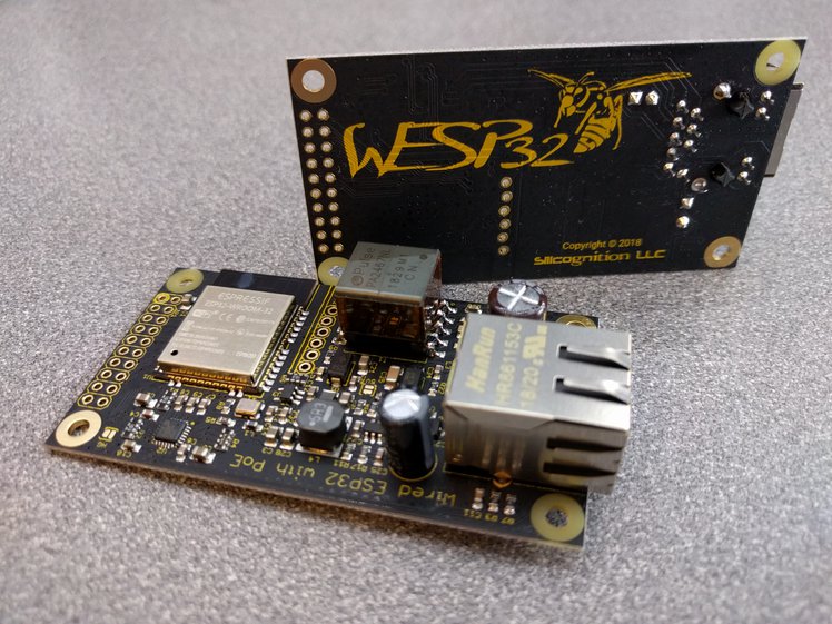
    Some boards were used for internal testing, some had to be sent back to Colorado Tech Shop for rework after finding issues during test, but today we were able to ship the first 205 units to Crowd Supply for delivery to backers next week.

    One of the boards was used for an experiment. I wanted to see if the board worked with the AI-Thinker ESP32-S module instead of the ESP32-WROOM-32:
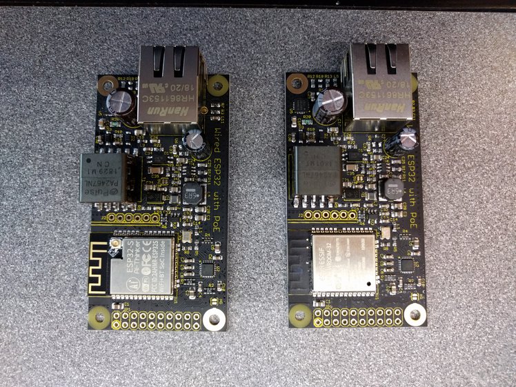
    I’m happy to report it seems to work just the same, so this module could be used to provide a future U.FL antenna connector option!
  • Production update, and testers!

    Patrick Van Oosterwijck12/30/2018 at 06:39 0 comments

    Last week it dawned on me that time keeps passing and I hadn't given much thought yet to how I was going to test the wESP32 and wESP32-Prog boards before we ship them!  A very important issue to start cranking on, especially with holidays and vacation eating up a good amount of time.

    wESP32-Prog tester

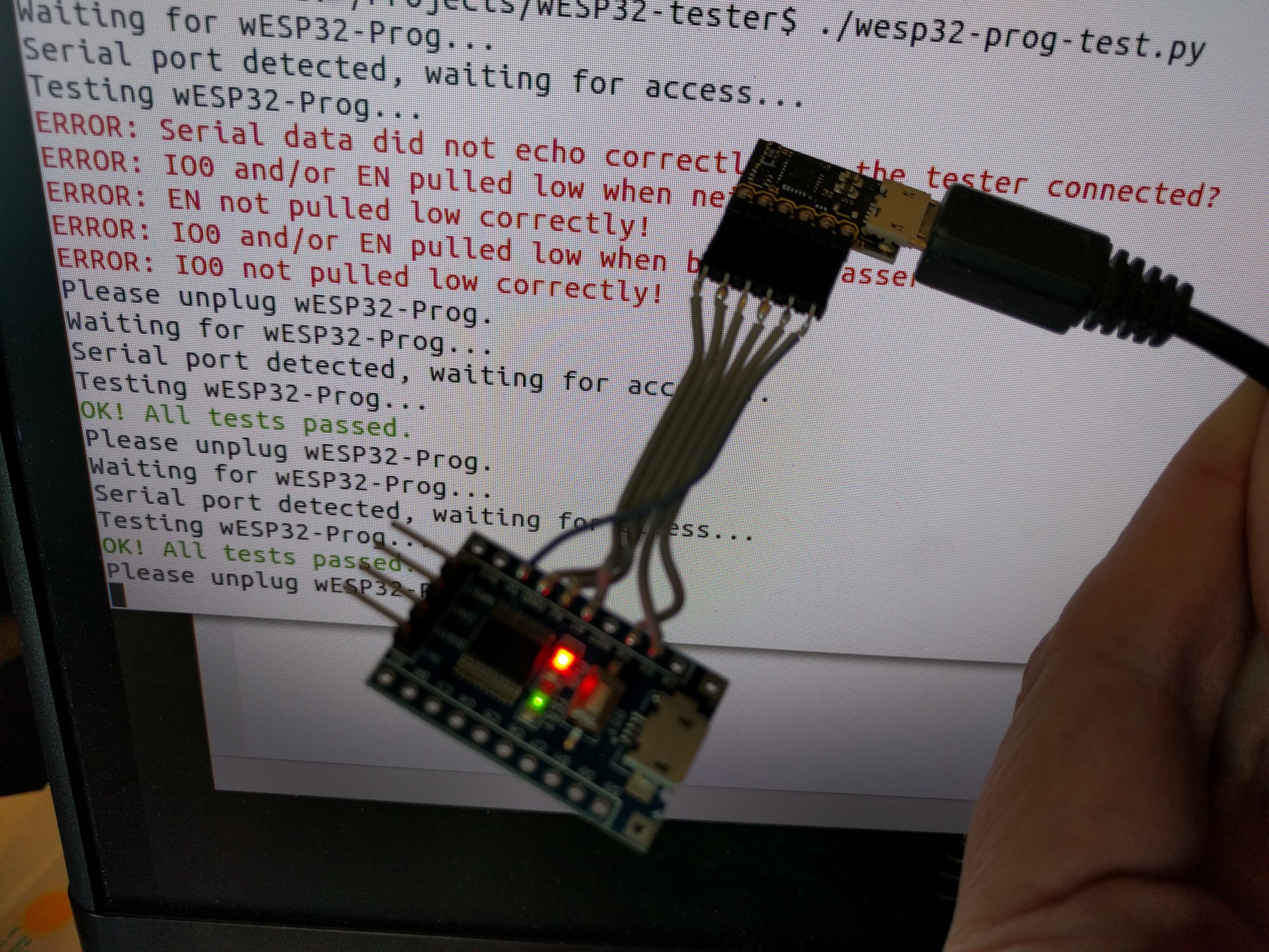
    The wESP32-Prog board is quite simple and because of this, the tester can be simple as well.  Building the tester only took half a day and this is what I ended up with:

    The hardware consists of a little STM8S103F3 board that can be had for less than a dollar on AliExpress.  I had it laying around and all I needed for this was a simple UART capable chip, so this was perfect.  I used the Sduino project project to speed up firmware development.   It looks slightly different from normal Arduino code because the SDCC compiler doesn't support C++, only C.  It was simple enough to get it to work though, resulting in this code:

    // wESP32-Prog tester using STM8S103 board and sDuino
    
    #define IO0   PA1
    #define EN    PA2
    
    void setup() {
      // Initialize digital pin LED_BUILTIN as an output.
      pinMode(LED_BUILTIN, OUTPUT);
      digitalWrite(LED_BUILTIN, 1);
      // Initialize EN and IO0 test pins as input with pullup
      pinMode(IO0, INPUT_PULLUP);
      pinMode(EN, INPUT_PULLUP);
        // Init serial port to 115200 bps
      Serial_begin(115200);
    }
    
    void loop() {
      // Read a byte from serial port
      int c = Serial_read();
      // Did we get a byte?
      if (c >= 0) {
        // Set lowest bit to value of IO0
        c = (c & 0xFE) | (digitalRead(IO0) ? 0x01 : 0);
        // Set second lowest bit to value of EN
        c = (c & 0xFD) | (digitalRead(EN) ? 0x02 : 0);
        // Echo byte back with altered IO0 and EN bits
        Serial_write(c);
        // Set the green LED state according to the second highest bit
        digitalWrite(LED_BUILTIN, (c & 0x40) ? 0 : 1);
      }
    }

     All this does is when a byte comes in, echo it back with the bottom two bits replaced by the current state of the IO0 and EN signals.  The second to highest bit also sets the tester board's on-board LED state.

    This firmware works in conjunction with a little Python script on my Linux box:

    #!/usr/bin/env python3
    
    import os
    import glob
    import serial
    import time
    from termcolor import colored
    
    while True:
    
      print("Waiting for wESP32-Prog...")
        ports = []
      while not ports:
        ports = glob.glob('/dev/ttyUSB*')
        time.sleep(0.1)
    
      print("Serial port detected, waiting for access...")
        while (not os.access(ports[0], os.R_OK|os.W_OK)):
        time.sleep(0.1)
        print("Testing wESP32-Prog...")
        test_ok = True
      s = serial.Serial(port=ports[0], baudrate=115200, timeout=0.1)
    
      s.setRTS(False)
      s.setDTR(False)
      s.write(b'0')
      res = s.read(1)
      if (res not in [b'0', b'1', b'2', b'3']):
        print(colored("ERROR: Serial data did not echo correctly, is the tester connected?", 'red'))
        test_ok = False
      if (res != b'3'):
        print(colored("ERROR: IO0 and/or EN pulled low when neither is asserted!", 'red'))
        test_ok = False
    
      s.setRTS(True)
      s.write(b'0')
      if (s.read(1) != b'1'):
        print(colored("ERROR: EN not pulled low correctly!", 'red'))
        test_ok = False
    
      s.setDTR(True)
      s.write(b'0')
      if (s.read(1) != b'3'):
        print(colored("ERROR: IO0 and/or EN pulled low when both are asserted!", 'red'))
        test_ok = False
    
      s.setRTS(False)
      s.write(b'0')
      if (s.read(1) != b'2'):
        print(colored("ERROR: IO0 not pulled low correctly!", 'red'))
        test_ok = False
    
      if (test_ok):
        print(colored("OK! All tests passed.", 'green'))
        s.write(b'@')
    
      s.close()
      print("Please unplug wESP32-Prog.")
        while ports:
        ports = glob.glob('/dev/ttyUSB*')
        time.sleep(0.1)

     What this does is wait for the wESP32-Prog board to be plugged in, which will create a /dev/ttyUSB0 device.  For some reason, trying to immediately open the serial device after this threw an access error, so we wait until it becomes accessible and then open it.

    Testing ensures that when we send a byte, the STM8 micro echoes a (modified) byte back to us.  We do this with various states of the RTS and DTR signals which control...

    Read more »

View all 29 project logs

Enjoy this project?

Share

Discussions

berlindx wrote 08/29/2024 at 18:27 point

Any chance I could get the cad files for the latest version in something other than sketchup? A .step would be great. Anything that solidworks can use ultimately. Thanks!

  Are you sure? yes | no

Patrick Van Oosterwijck wrote 08/30/2024 at 02:12 point

Sorry I don't have anything but the contributed Sketchup files.

  Are you sure? yes | no

YuryyKA wrote 07/20/2023 at 09:21 point

Revision with RTL8201 WiFi works stably together with wired Ethernet?

My previous project on ESP 32 + LAN8720 works stably with WiFi and wired Ethernet simultaneous.
The new project on RTL 8201 + ESP32 does not work stably when both interfaces enabled.
The wired interface is constantly Link Up/Link Down. WiFi ping delay from 500ms to 1,5s and does not connect normally.
But if uncheck one of the interfaces in the project settings, the second one works stably.
I use ESP-IDF. The difference from your scheme is that I use an internal RMII Clock from IO 17.

Best regards, Yuryy

  Are you sure? yes | no

Patrick Van Oosterwijck wrote 08/30/2024 at 02:13 point

Odd, I have not seen this in my testing with the IDF AP code.

  Are you sure? yes | no

nascom86 wrote 03/19/2023 at 20:29 point

Hey Patrick. Is the eagle project(board layout) for the wesp32 also available? I can only find the eagle files for the programmer.

  Are you sure? yes | no

pcs35a wrote 01/15/2023 at 16:10 point

I think it would be great, if tasmote would be supported. Do you have any plans on this?

Here is a thread for that, which was closed 6 months ago: https://github.com/arendst/Tasmota/issues/8503

I have a wESP32 and did not start to set up the toolchain, because I fear the effort building it for myself. Maybe, could you provide a hex-file, based on tasmota? I think it would make the entry to the wESP32 much easier, which helps you to reach more people and sell more wESP32.

  Are you sure? yes | no

Patrick Van Oosterwijck wrote 01/16/2023 at 22:52 point

I'm all for supporting more software, but I always get requests such as this for support of these super complex projects with a gazillion dependencies that I know nothing about. I don't just know about every firmware in existence, it takes a ton of effort on my part as well to learn about them.

According to this https://templates.blakadder.com/silicognition_wESP32.html the wESP32 should be supported.  Is this not the case? [I have no idea what that confusing config string might mean.]

Is there a problem with the new PHY of revision 7?  The Tasmota doc seems to indicate that it only supports the old IDF 3.x Ethernet PHYs: https://tasmota.github.io/docs/Commands/#ethernet

Do you know if this is the case?  Which IDF or Arduino version is this built on?  If it's IDF 3.x or Arduino Core < 2.0, there's no hope until they get that up to date.

  Are you sure? yes | no

pcs35a wrote 01/29/2023 at 17:43 point
Dear Patrik,

thank you for your quick answer. I agree 100 %, the tasmota project is insanely complex and providing long-term support is one of its own task.

Unfortunately I cannot answer any of your questions because I simply are not deep enough inside the matter.

If there was an tasmota-sensors.bin for wESP32 (even an older version with auto discovery for Home Assistant is fine), it would fulfill my use-case completely, since using a temperature sensor (e.g. 18DS20 or BME280) and reading some digital inputs and setting some digital outputs is ideal for me. Maybe, there are some other users for which this is an argument for buying the wESP32.

I have flashed the tasmota32.bin image to the wESP32, and the template already includes e.g. GPIO16 = ETH MDC and GPIO17 = ETH MDIO. Probably the libraries to communicate with the Ethernet module are not part of the .bin, because the ESP is connected to WiFI, bit not via Ethernet.

I'll just wait and hope for some support in the future :)

Edit 27th April 2023: the wESP32 should be supported by Tasmota according to https://github.com/arendst/Tasmota/issues/8503
I'll give it a try soon :)

  Are you sure? yes | no

Patrick Van Oosterwijck wrote 01/16/2023 at 21:30 point

Hi, the Si3404 does not support that much power output, you'd need a different PoE controller, synchronous rectification on the secondary and scaled up power parts such as the flyback transformer.

  Are you sure? yes | no

Ondrej Hanus wrote 11/08/2022 at 15:00 point

Hi Patric, I am a little confused about how the booting sequence of WESP32-v7 works. The ESP must read the IO0 sometime during booting, but IO0 is also wired to the output of a 50 MHz oscillator. Since the X1 and ESP are wired to the same EN signal, are they not enabled simultaneously? I suppose there should be some delay that secures the reading of the IO0 state first and then allows the oscillator, but I am not sure. Thanks 

  Are you sure? yes | no

Patrick Van Oosterwijck wrote 11/17/2022 at 21:05 point

The startup of the oscillator is slow enough that the IO0 level is already latched before the 50 MHz comes on.

  Are you sure? yes | no

LAUTARO SERRAV wrote 04/22/2022 at 17:21 point

Hi Patrick I just want to ask you about this board since I got one for myself and I have some issues to put it on work. I have an ubiquiti US 48 switch which I know it has PoE+ with IEEE 802.3af/at and IEEE 802.3bt on some ports (from 41 to 48 ports) but I couldn´t run the board in any of the ports.

Is my wire bad? Maybe I´m using a different ethernet cable, could you help me with the cable standard (if it needs to be wired as A or B).

I´ll really appreciate your help with my issue.

  Are you sure? yes | no

Patrick Van Oosterwijck wrote 04/22/2022 at 18:23 point

Hmm, odd.  The board it supposed to automatically work with either cable, and with power over data pairs or power over spares.

  Are you sure? yes | no

LAUTARO SERRAV wrote 04/22/2022 at 19:10 point

Yes, that´s also seems weird to me because I thaught the same. But making some research in the PoE section of my switch datasheet I found this:

https://dl.ui.com/ds/usw_pro_poe_ds

I´m a little bit confused about it, I don´t know where exactly the problem is at.

  Are you sure? yes | no

joeltroughton wrote 07/07/2022 at 13:46 point

Is this with the updated RTL8201 board? I have an issue where certain switches don't play nice with the RTL8201, but work fine with the older LAN8720. 

The link LED flashes on and off as the connection is established and soon dropped. Disabling auto-negotiation on the PHY solved the issue for me, but I'm keen to know if its the PHY, switch, or ESP-IDF driver

  Are you sure? yes | no

Thijs Leegwater wrote 01/10/2022 at 13:35 point

Hi, I've been using these wesp's with great succes in a large project, but I need 10 more in about a week. I had an outstanding order, but it got canceled, everything is out of stock until the end of februari. Anyone with some surplus stock who is willing to sell them to me?

  Are you sure? yes | no

Patrick Van Oosterwijck wrote 02/24/2022 at 17:00 point

As a quick update, my CM is currently building 1000 more units, I expect them to arrive in the beginning of March.

  Are you sure? yes | no

LAUTARO SERRAV wrote 12/16/2021 at 13:48 point

Hi guys, i´ve just have one doubt about this module. The PoE power supply works with all PoE specifications (meaning for example +24V, +48V) or it´s just pasive PoE? Thanks

  Are you sure? yes | no

Patrick Van Oosterwijck wrote 02/24/2022 at 17:04 point

This works only with IEEE 802.3 at/af standards compliant equipment, not "passive" or low voltage (24V / 12V) non-standard stuff.

  Are you sure? yes | no

evanevery wrote 11/22/2021 at 20:07 point

I'm trying to add Wesp32 functionality to several of my libraries.  The basic issue I am having is trying to find substitute objects classes for the standard Arduino Ethernet Library (Ethernet.h).  Currently I am using Ethernet.h to set up an onboard NIC in a Mega2560 variant.  I simply create a EthernetServer and EthernetClient object to handle raw TCP communications over specific ports to/from network targets.  My device functions as BOTH a server and client in this regard.

So, I understand  I need to use ETH.h instead of Ethernet.h but there are far fewer objects available with this library.  I see some folks using "WiFiServer" from the WiFi.h library but this does not seem obvious to me (shouldn't that be for a WiFi component?  How would I descriminate if I was using both wired/Wifi at the same time?)

I'm also NOT trying to build a WebServer as I need to handle and process all inbound/outbound communications manually.  I don't need/want that level of abstraction...

Anyway, I've been digging around for several hours and can't find a clear answer.  Am I missing something?  So, can someone give me a hint?

TLDR:  What is the most direct way to implement something similar to Ethernet.h's EthernetServer and EthernetClient objects while using the ETH.h library required for Wesp32?

  Are you sure? yes | no

Nate wrote 12/25/2021 at 19:55 point

I had the same problem. The WebServer class worked, but like you I didn't want a webserver, just TCP sockets. I looked at WebServer for how to do it, this works:

http://n4te.com/x/3699-QTnd.txt

  Are you sure? yes | no

Håkon Nessjøen wrote 10/25/2021 at 13:28 point

Hi, I recently bought a few wesp32 rev7, and tried updating my code. First I had the same issue as @ckuah, that platformio didn't use the newest libraries. But after fixing this, it just never receives an IP with DHCP.

But now my issue is that Wifi.onEvent() does not work. I also tried using the internal 

EDIT: So I figured it out. You need to use the following handlers instead:

esp_event_handler_register(ETH_EVENT, ESP_EVENT_ANY_ID, &_event_handler, NULL); esp_event_handler_register(IP_EVENT, IP_EVENT_ETH_GOT_IP, &got_ip_event_handler, NULL);

One of them gives you ethernet events, and the other ip-events. The WiFi.onEvent API seems to be deprecated. You also need to register the handlers after ETH.begin(), buf before ETH.config(). At least, that is my findings.

Also, if using PlatformIO, you need the following changes in your platformio.ini file:

platform = https://github.com/platformio/platform-espressif32.git#feature/arduino-upstream

platform_packages = platformio/framework-arduinoespressif32 @ https://github.com/espressif/arduino-esp32.git#2.0.0

  Are you sure? yes | no

Patrick Van Oosterwijck wrote 10/26/2021 at 19:35 point

Thank you for sharing your solution!

  Are you sure? yes | no

ckuah wrote 10/26/2021 at 23:32 point

Thanks a lot for posting your solution. I'd been using the Arduino IDE as a workaround.  With your solution I've been able to use PlatformIO again. Really appreciate it!

  Are you sure? yes | no

ckuah wrote 09/30/2021 at 01:57 point

Hi, I recently purchased the new wESP32 rev 7 with RTL8201 Ethernet PHY. The software I've written for the older version of the wESP32 no longer works because it doesn't work with the new RTL8201 chip. 

I'm using PlatformIO and have updated the ESP32 platform to the latest version: 3.3.2, but the code still cannot work with the RTL8201 chip.

The issue seems to come from this line of code: 

ETH.begin(0, -1, 16, 17, ETH_PHY_RTL8201);

PlatformIO says that ETH_PHY_RTL8201 is undefined.

Does anyone know what to do in order to fix the issue of working with the RTL8201 chip on PlatformIO?

  Are you sure? yes | no

Patrick Van Oosterwijck wrote 10/21/2021 at 17:28 point

Hi, sorry for the late response, I didn't see this comment.  Are you still having this problem or did you figure it out?

I'm not certain how exactly to accomplish this is PlatformIO, but if you use IDF, it needs to be version 4.x minimum and if you use the Arduino core it needs to be version 2.x minimum.  Maybe if PlatformIO doesn't integrate the latest Arduino Core yet, you have to use the staging version as described here:

https://docs.platformio.org/en/latest/platforms/espressif32.html#using-arduino-framework-with-staging-version

  Are you sure? yes | no

Tom Aubier wrote 12/31/2020 at 12:59 point

Hi, I’ve encountered an issue while trying to run an MQTT client on the wESP. I’m using the simple client library provided on the MicroPython GitHub repository and everything appears to be functioning flawlessly when testing the code in the MicroPython WebREPL. However I get a `IndexError: list index out of range` error as soon as I try running it in the `main.py` file or thought the serial prompt.

The issue seem to be related to the socket library failing when initiating the connection to the MQTT broker however I’m unable to find any way around this problem. Have you ever encountered something like this?

Btw I've provided more detail on this issue on this post: https://stackoverflow.com/q/65520905/9645937?sem=2

Cheers!

  Are you sure? yes | no

Patrick Van Oosterwijck wrote 01/05/2021 at 18:48 point

Hi Tom,

I hope someone else can help you with this, since this very much seems like a software issue internal to MicroPython, and I mostly keep myself on the hardware side of things. :)

It looks like you accepted an answer for the StackOverflow post so this is resolved?

  Are you sure? yes | no

MrNoname3 wrote 04/16/2020 at 14:44 point

Hi everyone,
I want to build my own ESP32 ethernet PCB to a specific application and I have a question. I need an ATTINY85 to my project too and I want replace the PMS150C with this ATTINY. Can you share the PMS150C code, please? I just want to see the delays and I/O states of the reset.
I read this article:
https://www.crowdsupply.com/silicognition/wesp32/updates/the-phy-reset-saga
And this is my hypothesis:
1. Usb serial programmer resets the ESP and the PMS150C
2. PMS150C oscillator enable pin go to LOW (the oscillator is disabled).
3. PMS150C PHY enable pin go to LOW (the PHY is disabled.)
4. 200ms delay in PMS150C.
5. PMS150C oscillator enable pin go to HIGH (the oscillator is enabled).
6. 100ms delay in PMS150C.
7. PMS150C PHY enable pin go to HIGH (the PHY is enabled.)
I saw the 2. oscilloscope picture on the link given above. I'm not an oscilloscope expert so I didn't exactly understood. Should I make between point 5 and 6 the PHY enable pin HIGH and immediately LOW before the delay, or what is that?
Thank you for your help!

  Are you sure? yes | no

Patrick Van Oosterwijck wrote 04/16/2020 at 15:59 point

Hi,

I don't have access to the PC that has that code right now (home due to Covid19) but the functionality is pretty much as you describe.  The thing that confuses you is when the PMS150C is not yet out of reset, the PHY enable is high (weak pull up) before the code runs that pulls it low.  This doesn't seem to cause any issue.  A similar thing was happening on the oscillator enable, but there I had to add a pull-down to prevent this, otherwise the PHY still didn't initialize correctly.

So, the whole sequence is:

Pull-down on oscillator enable to default low -> ESP32 EN / PMS150C reset goes high -> PMS150C boots and pulls both oscillator and PHY enable down -> Wait 200 ms -> Pull oscillator enable high -> Wait 100 ms -> Pull PHY enable high.

  Are you sure? yes | no

MrNoname3 wrote 04/16/2020 at 17:12 point

Hello,

Thank you for your answer! Now I understand everything.

  Are you sure? yes | no

roma wrote 08/24/2020 at 09:43 point

Hello Patrick. I am making a similar project, but for automotive use (CAN/KLINE/ENET and similar protocols). I have made quite of esp32 test boards too, still not finished yet. My question is - why you actually have to reset the PHY? I never had any boot issues (could well be my luck), and I am just delaying everything from ESP32 on the boot, so RMII is not engaged by any means, and they are just pulled high (startup delay which is less than 100nF charge time ).

I am just pulling low the oscillator EN with 10k resistor, and then supply HIGH with IO14. Pin 15 (nRST) of LAN8720 is pulled high via 4.7k resistor, and loaded with 100nF ceramic capacitor. Driving GPIO0 as ref clock input. Any suggestion what can go wrong with such setup? The RMII being high could affect LAN chip?

Many thanks in advance.

  Are you sure? yes | no

Patrick Van Oosterwijck wrote 08/24/2020 at 17:04 point

@roma It's been a while since I last looked at it, so I'm a bit rusty on the details. I think it works fine to control the PHY reset and oscillator from the ESP32 if you have available I/O to do it.  For the wESP32, I wanted to keep as many I/O available to the user, since so many were already in use by the RMII bus.  So I wanted an external solution, that wouldn't take up ESP32 I/O or rely on ESP32 code, to bring up the PHY correctly while not interfering with ESP32 programming.

I think the key things are:

- If ESP32 EN is low, make sure the oscillator is off and doesn't put the clock on IO0 since it may be in use for programming.

- Either after EN release or cold boot (power up), make sure the oscillator starts before the PHY reset is released.  The datasheet specifically says clock must be present while in reset to reset correctly.

- Then release the PHY reset.

There are various ways to accomplish this.  I first followed the way Olimex had done it with a voltage detector with delay, which seemed to work on my prototypes but proved unreliable in production, with 10% of boards not initializing correctly.  Then I went with the PMS150C solution, which has been working 100% reliably.  I think the key is that it programmatically guarantees the correct sequence, and is not dependent on variations related to RC component tolerance, reset threshold variation, oscillator startup time, etc.  If you can do the same with ESP32 I/O, it should work as well.  But if you mix RC timing into it, you may see problems.

  Are you sure? yes | no

roma wrote 08/26/2020 at 20:57 point

Hello @Patrick Van Oosterwijck ,\

Many thanks for detailed answer, I really appreciate. I understand your intentions with many GPIO's, and your solutions does sound bullet proof.

I still have couple of question:

- Could you sell few of PMS150C's? I've heard you've got plenty :)

- Could you share contact for purchasing reprogrammed units, along with the firmware? For my production purposes, it needs to be on a scale.

And on the technical side. On your schematics I can see that refclock (pin 14) of LAN8720 is not wired. According to the datasheet, its either INT or output clock from internal oscillator (25Hz). I am wondering why you don't have it pulled high - could this be a problem of those 10% of units?

Now, regarding clock setup for RMII.

Here's a quote from LAN8729 datasheet:

///////////////////////////////////////////////////////////////////

3.7.4.2   REF_CLK Out Mode

To reduce BOM cost, the device includes a feature to generate the RMII REF_CLK signal from a low-cost, 25MHz fundamental crystal. This type of crystal is inexpensive in comparison to 3rd overtone crystals that would normally be required for 50MHz. The MAC must be capable of operating with an external clock to take advantage of this feature as shown in Figure 3-8.
In order to optimize package size and cost, the REFCLKO pin is multiplexed with the nINT pin. In REF_CLK Out mode, the nINT functionality is disabled to accommodate usage of REFCLKO as a 50MHz clock to the MAC.

Note: The REF_CLK Out Mode is not part of the RMII Specification. Timing in this mode is not compliant with the RMII specification. To ensure proper system operation, a timing analysis of the MAC and LAN8720 must be performed."

///////////////////////////////////////////////////////////////////

Furthermore, it supports 25Mhz clock to be supplied on XTAL1 (XTAL2 should float in this case), which will make it output 50Mhz on pin 14, thus providing an external RMII clock for GPIO0. Price of  25Mhz is similar to the one you have  installed of 50Mhz.

All of the above is configured with boot-stapping pin nINTSEL to low. So, in this setup having nRST low would also release GPIO0 from being affected during boot (it does not output refclock when in reset), hence only one "delayed" startup pin, either by GPIO or some simple delay IC (or even a capacitor?). I would appreciate your suggestions.

Do you have any contact outside hackaday for the matter of  PMS150C's or perhaps other projects?

Kind regards,

  Are you sure? yes | no

Patrick Van Oosterwijck wrote 08/26/2020 at 21:54 point

@roma Interrupt mode is selected for pin 14 by means of the LED2/NINTSEL pin that is pulled up.  Since the interrupt is an output and not used, it can be left unconnected.
Let's discuss the PMS150C in private chat, I'll give you my email address.

  Are you sure? yes | no

Patrick wrote 03/10/2020 at 19:03 point

I created an Eagle library footprint for anyone who wants to use it. It should be good, but I recommend someone double-check my work. Let me know if there are issues. 

https://github.com/mechatroniks-git/eagle-libraries

  Are you sure? yes | no

Patrick Van Oosterwijck wrote 03/10/2020 at 19:32 point

Thanks Patrick!

I looked it over and everything seems to line up, but it looks like on the GPIO header the pins are reversed left-to-right from pin 7 and up.

  Are you sure? yes | no

Patrick wrote 03/10/2020 at 20:47 point

Yup, device package had mixed up pin numbering, silly me, should be all fixed now.

  Are you sure? yes | no

lathoub wrote 03/06/2020 at 13:12 point

Hi everyone,

I just got me hands on the wESP32 and the webserver example is running just fine in the Arduino IDE. I want to use my existing Arduino <Ethernet.h> code on the wESP32, but there are not a lot of examples around. I'm looking specifically for example sending UDP packets.

Also, can I use the wireless capabilities of the wESP32 at the same time as the wired capabilities?

Thanks!

  Are you sure? yes | no

Patrick Van Oosterwijck wrote 03/10/2020 at 19:15 point

Hi,

Wireless is still available, but there may be some limitations on using wired and wireless at the same time that are mostly related to how deeply you dive into the software.  I'm not an expert in the software side of ESP32.  I have tested Espressif's WiFi to Ethernet bridge code successfully on the wESP32: https://www.crowdsupply.com/silicognition/wesp32/updates/ethernet-to-wifi-bridge-demo-code

Arduino may be too high level to be able to use both though.  As far as I know, the initialization code ties the TCP/IP stack to either interface, but not both at once.  Though I may be wrong, like I said, I'm not an expert on the software side of things.

  Are you sure? yes | no

Petr Karliak wrote 01/07/2020 at 10:26 point

Hello Guys,

I have to use a WatchDog on wESP32 to check and reset in case of freezing the Arduino core, but I managed to set it to Core0 and Core1 (Arduino). But I haven't enabled Wifi, so Core0 is idle, so it is happening that it is restarting all over again and again. I can't load new program to disable it down. I tryied the python tools, but with no luck. Anyone could help me what to try except manualy change the chip (whole ESP32) on wESP32?

Petr

  Are you sure? yes | no

Patrick Van Oosterwijck wrote 01/07/2020 at 15:56 point

Sorry I wasn't able to help you with this problem Petr, let's hope someone else here knows more about this.  Anyone?

  Are you sure? yes | no

Ashley wrote 12/06/2019 at 14:30 point

We are based in South Ontario Canada.  I already have one of these for testing for a new product we want to sell, i have a few questions and wishlist items:

- How do i upload code via Ethernet only (not USB)?  i cant find anything on the net / youtube with regards MicroPython and squirting it via Ethernet, they all reference USB.

- Are you planning to do a 802.3at version (30w [ish])?

- We need more analogue sensor pins, about 10 in total, i believe you have 5.  We need to control 5 LEDs and measure the current used by all 5 lines

- Does the 12v line have an internal current measurement sensor (i would assume it does being PoE driven), how would we access this via MicroPython?

- More RAM? although 4Mb (i believe this has) might be ok, more is always good, we have to get a whole website in this (the current one is 1.4Mb, might be slighy larger for this device but it all should fit)

For now the item we have should do as a really good start, we will likely need them by the multiple 10's or 100's once its all working, this project is live and R&D is working on the board now to try and get the program running we need.

Many Thanks

  Are you sure? yes | no

Patrick Van Oosterwijck wrote 01/07/2020 at 16:29 point

Hi Ashley,

Sorry I didn't see this sooner.  I wish the Hackaday.io system was more reliable in sending notifications when someone comments.  To make sure you get prompt responses you can try support@wesp32.com instead.  To answer your questions:

- Espressif supports OTA in IDF (https://docs.espressif.com/projects/esp-idf/en/latest/api-reference/system/ota.html) but it seems this hasn't made it into MicroPython yet, although there's work done for it (https://github.com/micropython/micropython/pull/3576).  If you just need to be able to update your MicroPython code it may be possible to implement your own system that updates the files in the filesystem, but if you need to update the MicroPython runtime as well, something more like the linked PR is needed.

- I'm not actively developing a 802.3at Type 2 (25W) system at the moment, but it's a natural progression that's definitely on the roadmap.  To limit risk I stuck to Type 1 (13W) this round, but a follow up product will go to Type 2.

- It's unfortunate but the Ethernet PHY interface takes up a lot of ESP32 pins so there aren't that many left for the user.  That said, to be honest the ESP32's ADC is pretty crappy.  You're much better off to add an external ADC that you control over I2C or SPI.  Such chips are pretty common, or add an external low cost ADC such as an EFM8 for the low level control and excellent analog peripherals.  I've done this for customer projects and the results are much better than using the ESP32 ADC.

- The 12V line does not have current sensing that is accessible from the ESP32, the PoE controller does this on the primary side.  A low-side current sense resistor, read by an ADC input is a simple way to add this function.

- I think you're mixing up RAM and flash sizes, but you're right that the standard ESP32-WROOM module may be a bit tight for large web content.  There is an ESP32-WROOM module with 16MB of flash though if you need it.  For bulk orders I can have this module populated instead.

  Are you sure? yes | no

graeme woollett wrote 11/19/2019 at 23:42 point

Hi Patrick

I've bought 5 boards and 2 have died.  First one the Phy gets hot, ethernet lights  don't come on, doesn't obtain an ip address.  Now a 2nd one won't get an ip either, no ethernet lights.

Seems that LAN PHY has died in both cases.

boot.py hasn't been altered in either case.  

Do you have any advice on how to stop them dying?

  Are you sure? yes | no

Patrick Van Oosterwijck wrote 01/07/2020 at 16:35 point

Hi Graeme,

Sorry about the late reply, the site didn't notify me and I was too busy to check here regularly.

This is odd, the only time I've seen PHY chips die has been when the ESP32 GPIOs were not configured right for the board, but if you are using the stock MicroPython and boot.py, and don't reconfigure the pins afterward, this should not be the case.

If you're willing to send them back to me I'd like to do a postmortem and repair or replace them.  Please contact me at support@wesp32.com to arrange this.

  Are you sure? yes | no

ego wrote 10/10/2019 at 11:27 point

Hi Patric,

Is there a physical dimensions document?

Even more helpful would be an eagle library like there is for arduino, raspberry pi, etc.

  Are you sure? yes | no

Patrick Van Oosterwijck wrote 01/07/2020 at 16:39 point

Hi @ego,

I've added wESP32-3-mechanical.pdf to the files section.  Let me know if that doesn't cover all the dimensions you need.  This will be added to the next revision of the manual as well.

  Are you sure? yes | no

Similar Projects

Does this project spark your interest?

Become a member to follow this project and never miss any updates