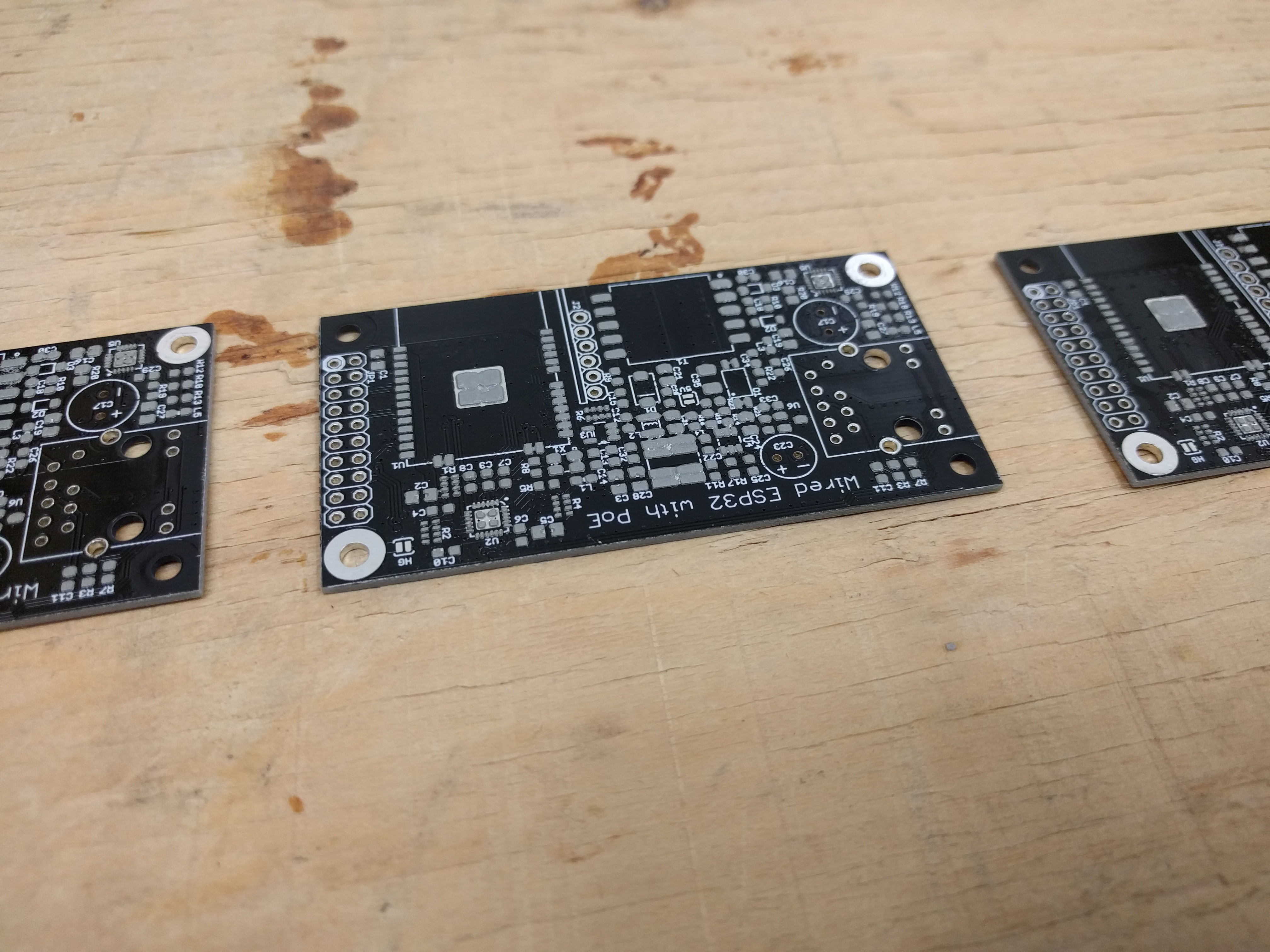
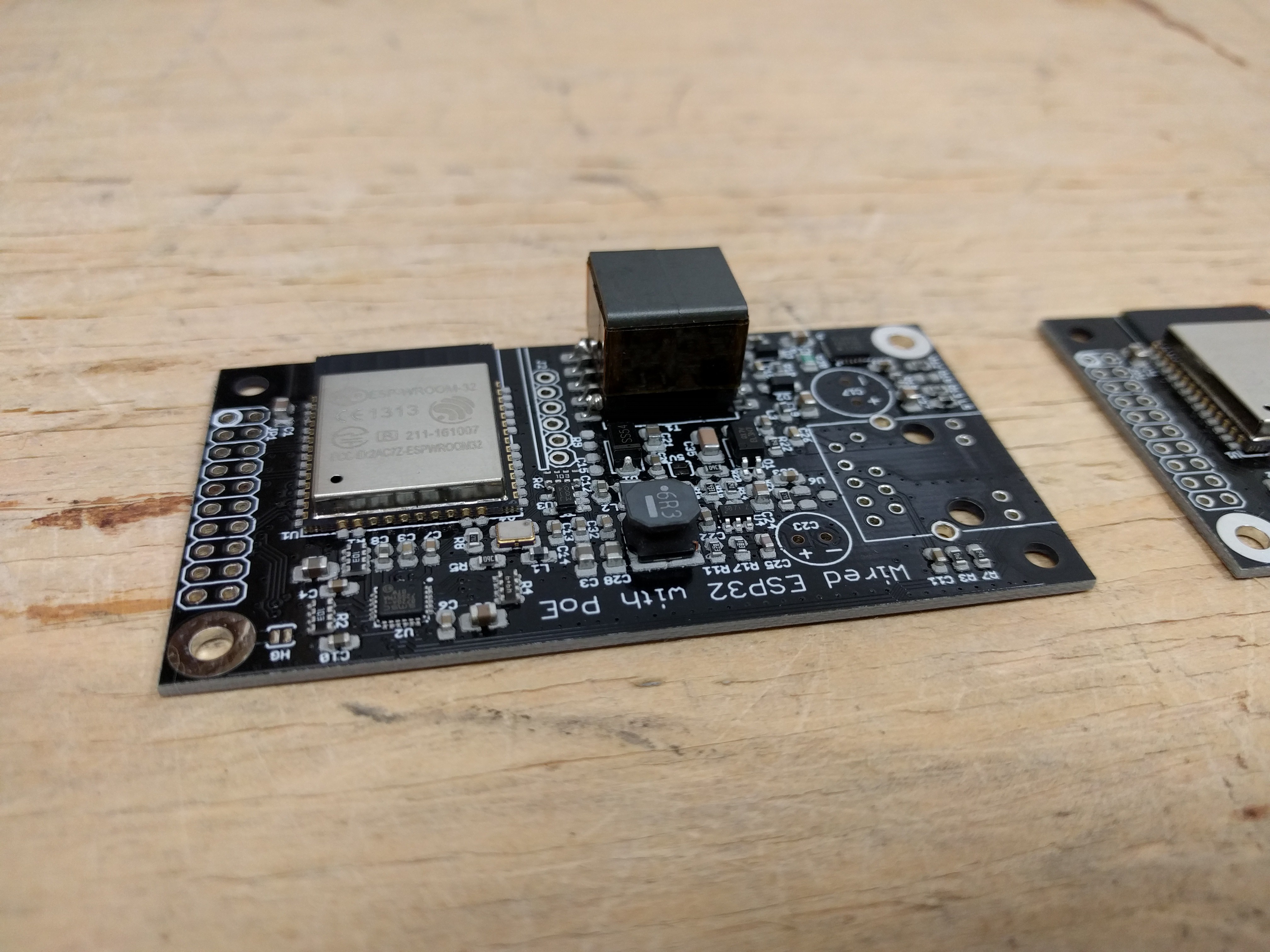
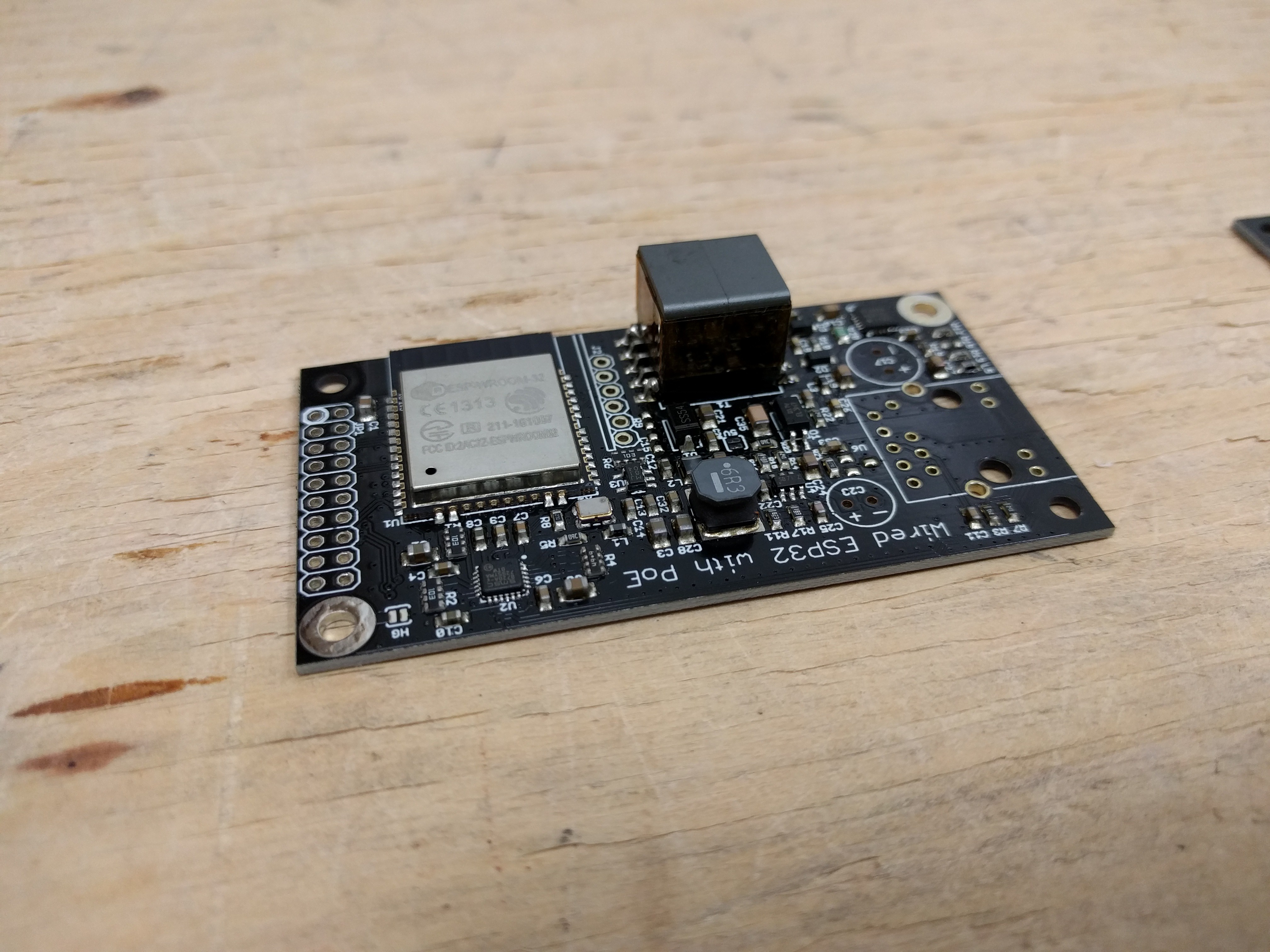
I found time to build four wESP32 prototypes yesterday! Here are some shots taken during the (manual) assembly process.
Stencil with board ready to be pasted:

Boards with solder paste, ready for assembly:

Most components placed:

After reflow:

All boards needed some touch up, my solder pasting was kinda messy with the frameless stencil and the old paste, so there was some bridging on the QFNs that needed to be fixed up.
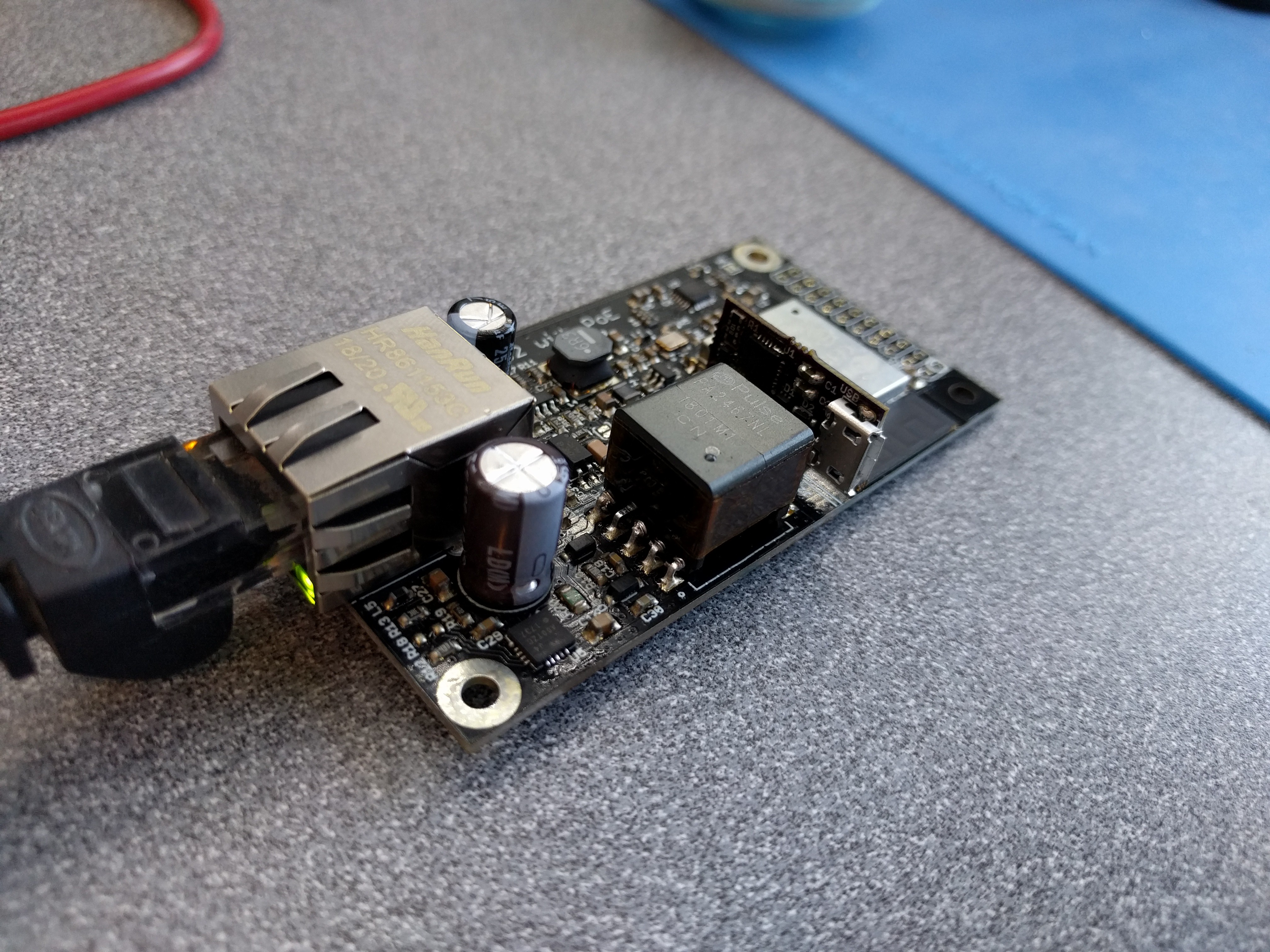
Then after I completed the assembly of the first prototype I plugged in the PoE Ethernet jack and immediately measured 11.4V on the V+ rail! Yay, what a relief! :) The PoE section seems to be immediately operational. I had some trouble programming the ESP32 using the ESP32-Prog submodule though. Switched to a different prototype I finished up, and on that one I could program the ESP32 right away! So I loaded the ESP-IDF Ethernet example and plugged it in:

Behold, blinking LEDs on the Ethernet jack and a sure sign of success! Checking the serial monitor, I could tell the device was successfully getting an IP address from DHCP as well. :)
This is what has been verified to work so far on some of these prototypes:
- PoE produces 11.4V on the V+ rail, and 5.1V when the 5V solder bridge is closed.
- Buck converter produces 3.3V to power the ESP32 and Phy.
- Ethernet Phy is operational and communicates with the ESP32, tested to the point of getting an IP address from DHCP.
- ESP32-Prog submodule and on-board logic manages the EN and IO0 signal correctly to allow programming, serial monitoring and 50MHz EMAC clock to work correctly.
I have two prototypes where all the above works, a third seems to work but for unknown reason it is not getting an IP address from DHCP, and on the fourth I can't seem to program the ESP32 yet. Still work to do to get those going but it seems likely these are just assembly issues and not a problem with the design. Let's hope.
More testing is still needed to make sure the design is sound:
- Check the power supplies and see how noisy they are, optimize snubbers and filters in the flyback stage to minimize noise and optimize the EMC.
- Check how much power can be pulled from the PoE with and without a heat sink attached. See if we get to 12.95W which is the target for 802.3af (802.3at Type 1). I hope to get there with a heat sink, but expect a lower maximum when no heat sink is used.
- Check how much power we can pull when the 5V option is selected. I'm not expecting to reach 12.95W here, since the flyback is optimized for 12V.
- Check if we have enough power and good enough signal with really long cables (does anyone know if there is a way to get a signal qualify figure from the phy?).
- Check how much power is available from the 3.3V rail for the specification.
 Patrick Van Oosterwijck
Discussions
Become a Hackaday.io Member
Create an account to leave a comment. Already have an account? Log In.
Quick info: wall mount boxes (switches, wall socket, ethernet wall socket, etc) are 65mm diameter and not 80mm what earlier was written.
Image:
https://orbanvillamossag.cdn.shoprenter.hu/custom/orbanvillamossag/image/cache/w900h500wt1/kotodoboz/IMT35101_sorolhato_doboz.jpg
There are two depths: normal is 45mm extended is 60mm. Almost anyone uses normal.
These are for brick wall or conrete wall (or any other masonry wall).
For drywall the diameter is either 65mm, or 68mm.
Pictures (65mm):
http://www.haluxvill.hu/image/cache/data/termek_kat_kep/IMT35150_tn-340x340.jpg
68mm:
http://www.haluxvill.hu/image/cache/data///906331-340x340.jpg
The 80mm is for junction box. (where wires meet, and goes for the main cabinet or another junction box, or wall plug/switches).
Image:
http://www.haluxvill.hu/image/cache/data/KAISER-1172-101919-0-340x340.jpeg
There are also 75mm diameter for junction box (not as common).
If bigger is needed those are rectangular, like 100x150mm, 150x150mm, 150x200mm, etc.
Picture:
https://www.mentavill.hu/_upload/images/catalog/403205/403205.jpg
Don't know if it is too late but the design should aim a more square design rather then a rectangular one.
Nice progress.
Are you sure? yes | no
Yeah I was actually thinking more along the lines of US junction boxes:
https://www.homedepot.com/p/Carlon-1-Gang-22-cu-in-Heavy-New-Work-Electrical-Box-BH122A-UPC/202065291
https://www.homedepot.com/p/Carlon-1-Gang-20-cu-in-New-Work-Ceiling-Box-with-Captive-Nails-B520A-UPC/205322767
I think getting the design more square would result in an overall bigger size I'm afraid. Unless I make it two sided and put the ESP32 on the back. There PoE isolation makes it hard to make it significantly smaller though.
Are you sure? yes | no
What about a round (circle) design?
Or a stackable version where the baseplate would be the PoE?
In that case, if one needs a beefier PoE (32W), he can have that baseplate?
75mmx40mm is 3000m2 (or 30cm2). 65mm circle design would have a 33.2cm2, it may work....
Are you sure? yes | no
It may... maybe a future version. :)
Are you sure? yes | no
Excellent work mate.
Are you sure? yes | no