Patrick Van Oosterwijck
-
Production update, and testers!
12/30/2018 at 06:39 • 0 commentsLast week it dawned on me that time keeps passing and I hadn't given much thought yet to how I was going to test the wESP32 and wESP32-Prog boards before we ship them! A very important issue to start cranking on, especially with holidays and vacation eating up a good amount of time.
wESP32-Prog tester
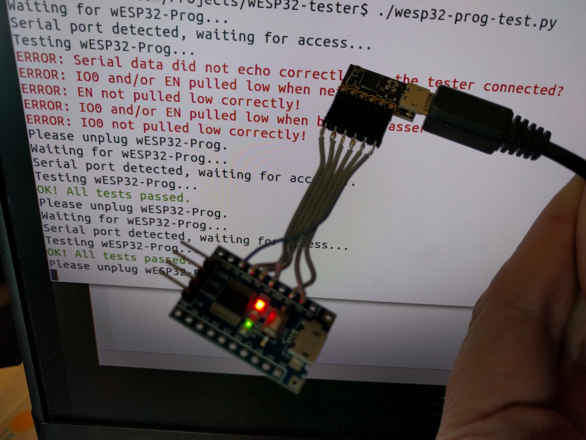
The wESP32-Prog board is quite simple and because of this, the tester can be simple as well. Building the tester only took half a day and this is what I ended up with:
![]()
The hardware consists of a little STM8S103F3 board that can be had for less than a dollar on AliExpress. I had it laying around and all I needed for this was a simple UART capable chip, so this was perfect. I used the Sduino project project to speed up firmware development. It looks slightly different from normal Arduino code because the SDCC compiler doesn't support C++, only C. It was simple enough to get it to work though, resulting in this code:
// wESP32-Prog tester using STM8S103 board and sDuino

#define IO0   PA1
#define EN    PA2

void setup() {
  // Initialize digital pin LED_BUILTIN as an output.
  pinMode(LED_BUILTIN, OUTPUT);
  digitalWrite(LED_BUILTIN, 1);
  // Initialize EN and IO0 test pins as input with pullup
  pinMode(IO0, INPUT_PULLUP);
  pinMode(EN, INPUT_PULLUP);
    // Init serial port to 115200 bps
  Serial_begin(115200);
}

void loop() {
  // Read a byte from serial port
  int c = Serial_read();
  // Did we get a byte?
  if (c >= 0) {
    // Set lowest bit to value of IO0
    c = (c & 0xFE) | (digitalRead(IO0) ? 0x01 : 0);
    // Set second lowest bit to value of EN
    c = (c & 0xFD) | (digitalRead(EN) ? 0x02 : 0);
    // Echo byte back with altered IO0 and EN bits
    Serial_write(c);
    // Set the green LED state according to the second highest bit
    digitalWrite(LED_BUILTIN, (c & 0x40) ? 0 : 1);
  }
}
All this does is when a byte comes in, echo it back with the bottom two bits replaced by the current state of the IO0 and EN signals. The second to highest bit also sets the tester board's on-board LED state.
This firmware works in conjunction with a little Python script on my Linux box:
#!/usr/bin/env python3

import os
import glob
import serial
import time
from termcolor import colored

while True:

  print("Waiting for wESP32-Prog...")
    ports = []
  while not ports:
    ports = glob.glob('/dev/ttyUSB*')
    time.sleep(0.1)

  print("Serial port detected, waiting for access...")
    while (not os.access(ports[0], os.R_OK|os.W_OK)):
    time.sleep(0.1)
    print("Testing wESP32-Prog...")
    test_ok = True
  s = serial.Serial(port=ports[0], baudrate=115200, timeout=0.1)

  s.setRTS(False)
  s.setDTR(False)
  s.write(b'0')
  res = s.read(1)
  if (res not in [b'0', b'1', b'2', b'3']):
    print(colored("ERROR: Serial data did not echo correctly, is the tester connected?", 'red'))
    test_ok = False
  if (res != b'3'):
    print(colored("ERROR: IO0 and/or EN pulled low when neither is asserted!", 'red'))
    test_ok = False

  s.setRTS(True)
  s.write(b'0')
  if (s.read(1) != b'1'):
    print(colored("ERROR: EN not pulled low correctly!", 'red'))
    test_ok = False

  s.setDTR(True)
  s.write(b'0')
  if (s.read(1) != b'3'):
    print(colored("ERROR: IO0 and/or EN pulled low when both are asserted!", 'red'))
    test_ok = False

  s.setRTS(False)
  s.write(b'0')
  if (s.read(1) != b'2'):
    print(colored("ERROR: IO0 not pulled low correctly!", 'red'))
    test_ok = False

  if (test_ok):
    print(colored("OK! All tests passed.", 'green'))
    s.write(b'@')

  s.close()
  print("Please unplug wESP32-Prog.")
    while ports:
    ports = glob.glob('/dev/ttyUSB*')
    time.sleep(0.1)
What this does is wait for the wESP32-Prog board to be plugged in, which will create a /dev/ttyUSB0 device. For some reason, trying to immediately open the serial device after this threw an access error, so we wait until it becomes accessible and then open it.
Testing ensures that when we send a byte, the STM8 micro echoes a (modified) byte back to us. We do this with various states of the RTS and DTR signals which control EN and IO0 respectively through the auto programming circuit. If everything comes back as expected, we print a success message, turn on the green LED on the STM8 board and wait for the board to be unplugged.
wESP32 tester
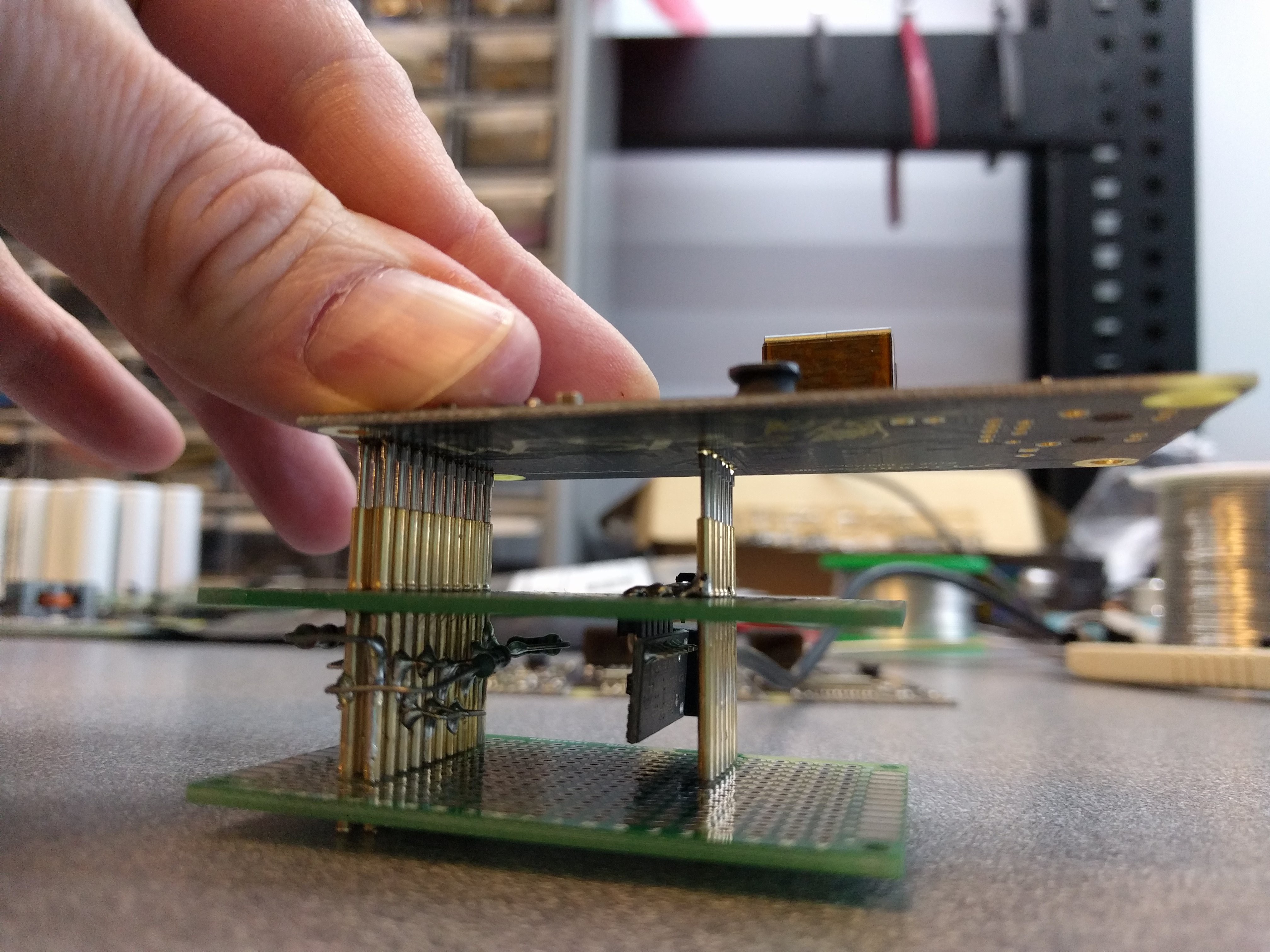
The wESP32 is more complex, so the tester has to be as well. We have a bed of nails that connects to the GPIO header and the programming port. The fixture has a wESP32-Prog module on board that connects to the wESP32 for programming and to run the testing sequence over the serial connection.
![]()
Software still needs to be written, but here's the gist. The test starts by plugging a PoE powered Ethernet cable in to the RJ45 and pushing the wESP32 onto the pogo pins. First a MicroPython image will be flashed to the ESP32 and a factory boot.py and test script will be loaded. The boot.py enables and configures the Ethernet port correctly for the wESP32 to establish a network connection. This script will remain on the units when they are shipped, so you will have a MicroPython install with working network connection straight out of the box! The test script will exercise the GPIO pins and measure the V+ voltage while a load of about 12 W is applied. Most of the GPIO pins will be connected together in physically spread out pairs of which one pin will be an output and the other an input. These will be driven alternately high and low to ensure connectivity from the module pads to the header footprint with no shorts.
When all these tests running on the ESP32 turn out successful, the test script will notify the PC over the serial port that the unit is OK, after which the test script will be erased and the unit is ready to go.
Production progress
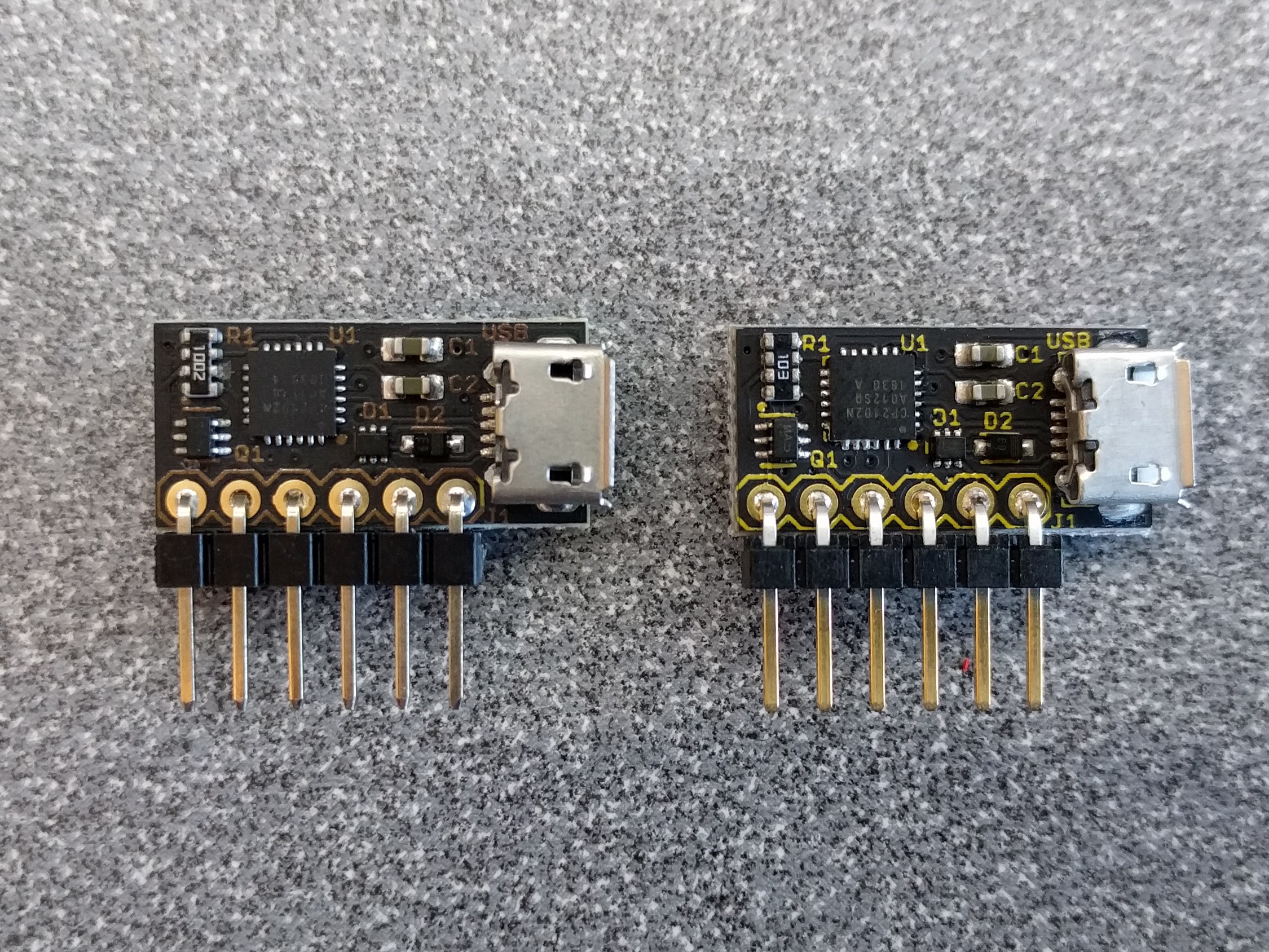
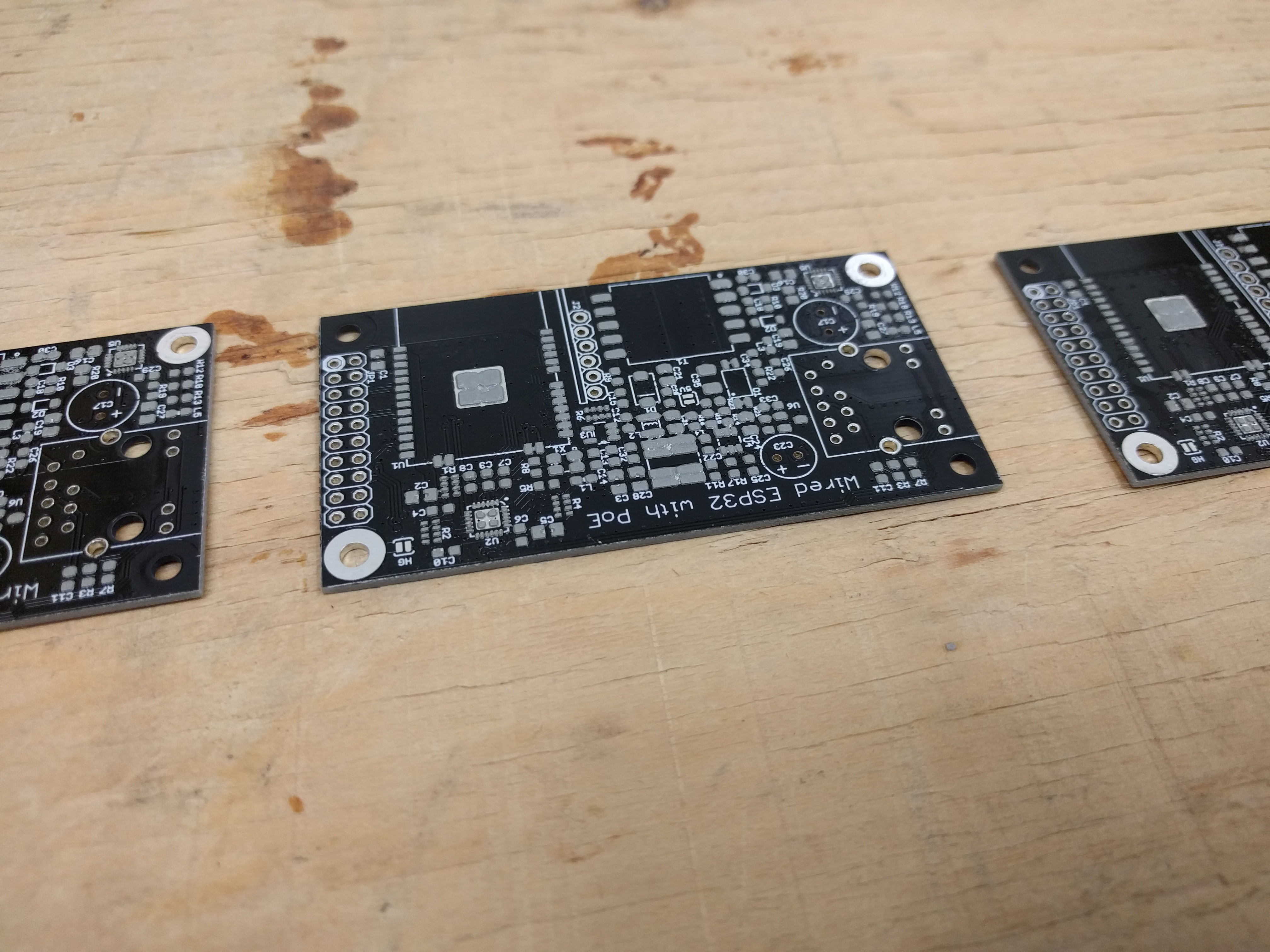
We received wESP32-Prog production units from both Colorado Tech Shop and Boktech! I am pleased with how fast Boktech turned around this order. What I am not pleased with is the way the product looks:
![]()
The unit on the left is one produced by Boktech. The one on the right is a production unit from Colorado Tech Shop. The Colorado Tech Shop unit looks beautiful, the unit from Boktech not so much. All units from Boktech have ugly brown silk screen like that, while it should be yellow. Before they started production, they sent me a picture of a unit for first article inspection, and that unit looked very good with nice yellow silk screen, so I approved it. Unfortunately, production didn't turn out the same. When I asked about it, they said the first article unit was handmade, not done in the normal production process! I think they are kind of missing the point of what a first article inspection is for... :-/ Unfortunately, in my discussion with them it has become clear they don't think anything is wrong with either the color change or producing an invalid first article, so I think I'll be looking to try a different Chinese CM.
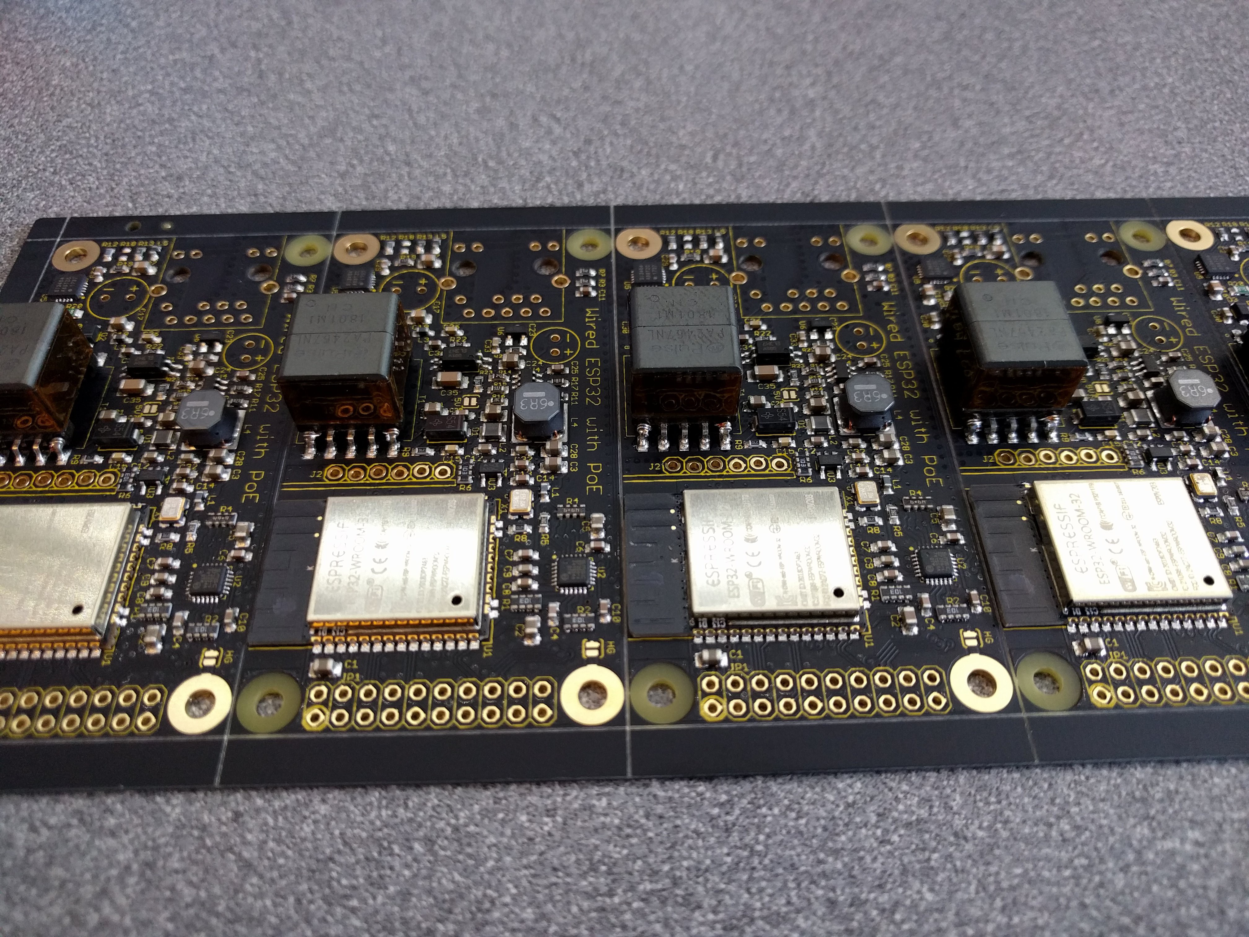
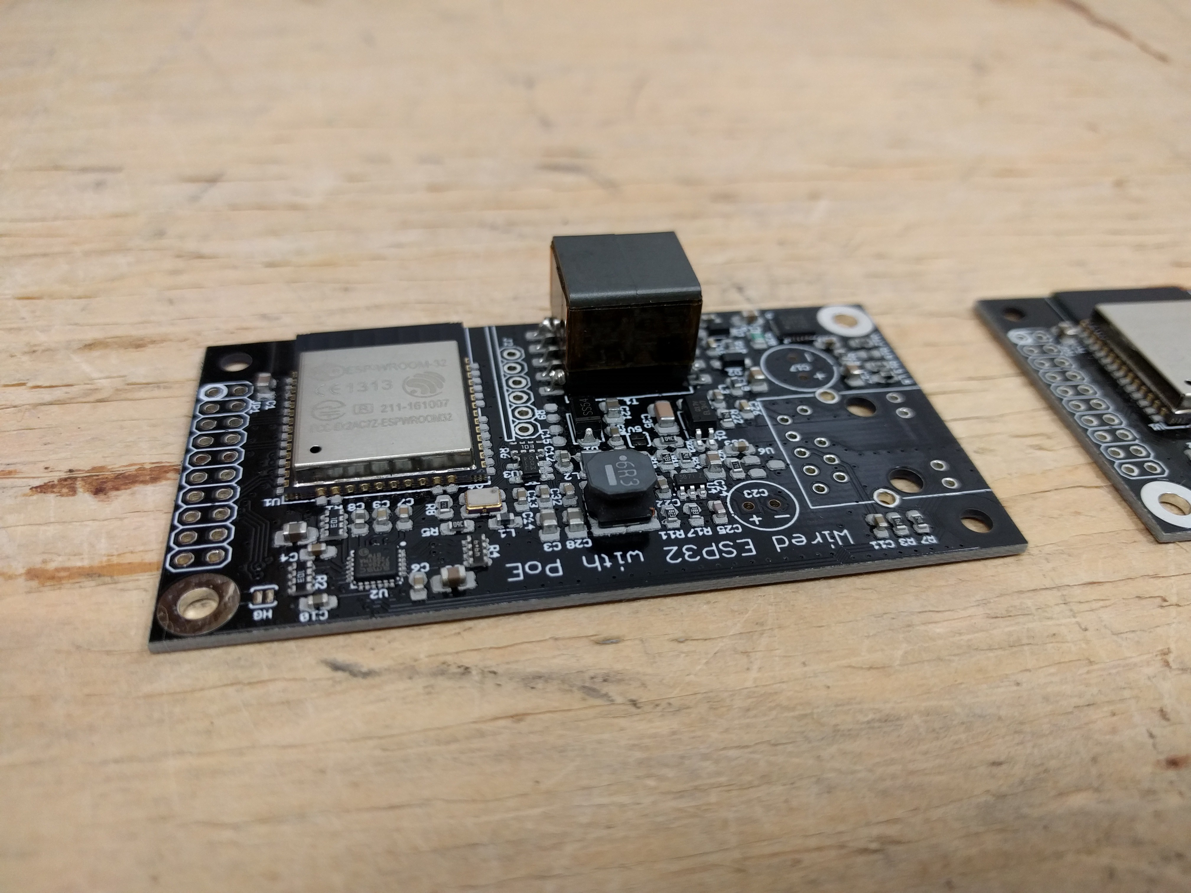
We also receive a first article wESP32 from Colorado Tech Shop:
![]()
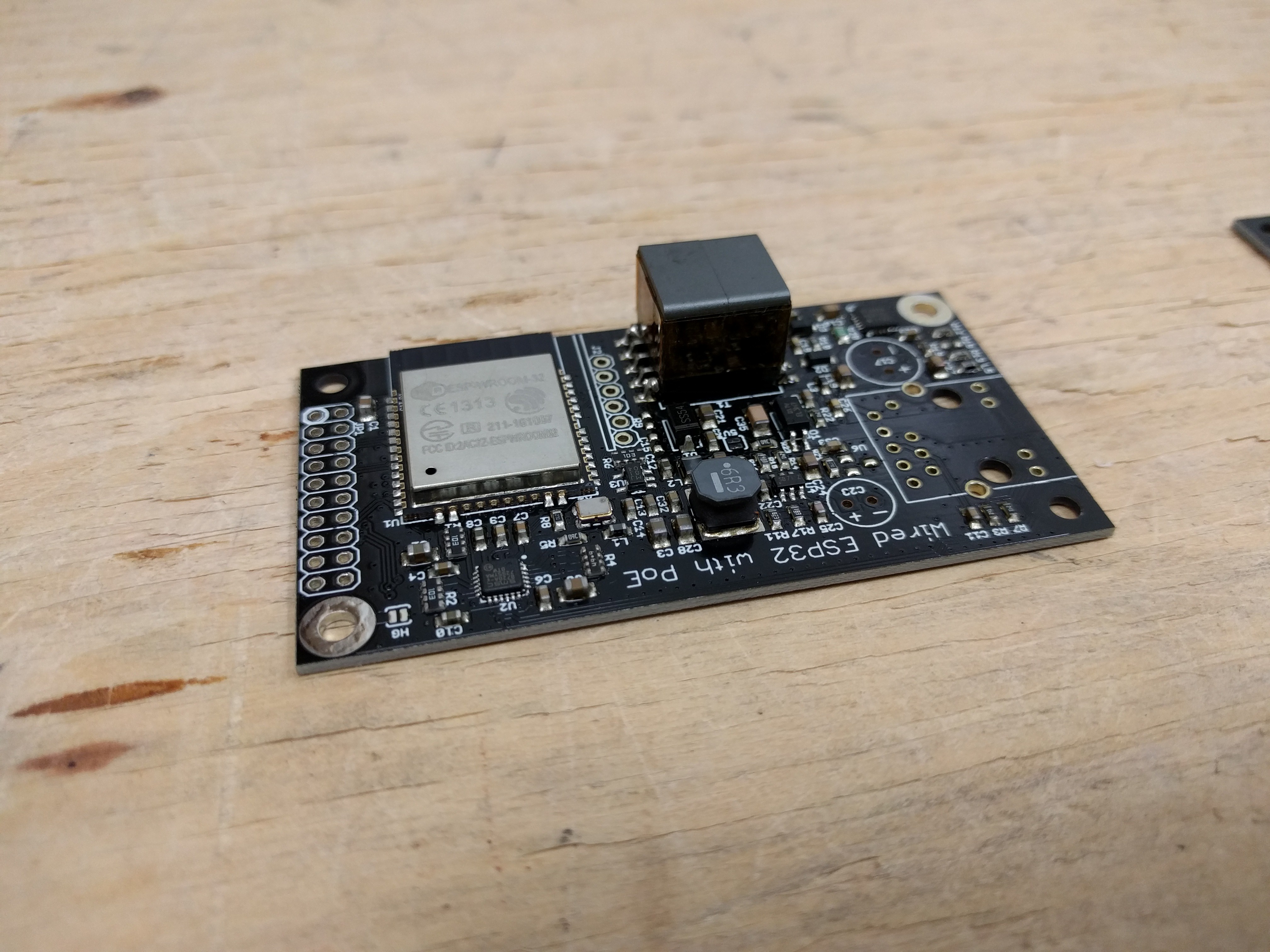
They turned out looking really good! I inspected the boards and quickly added the remaining components to one of the units for testing:
![]()
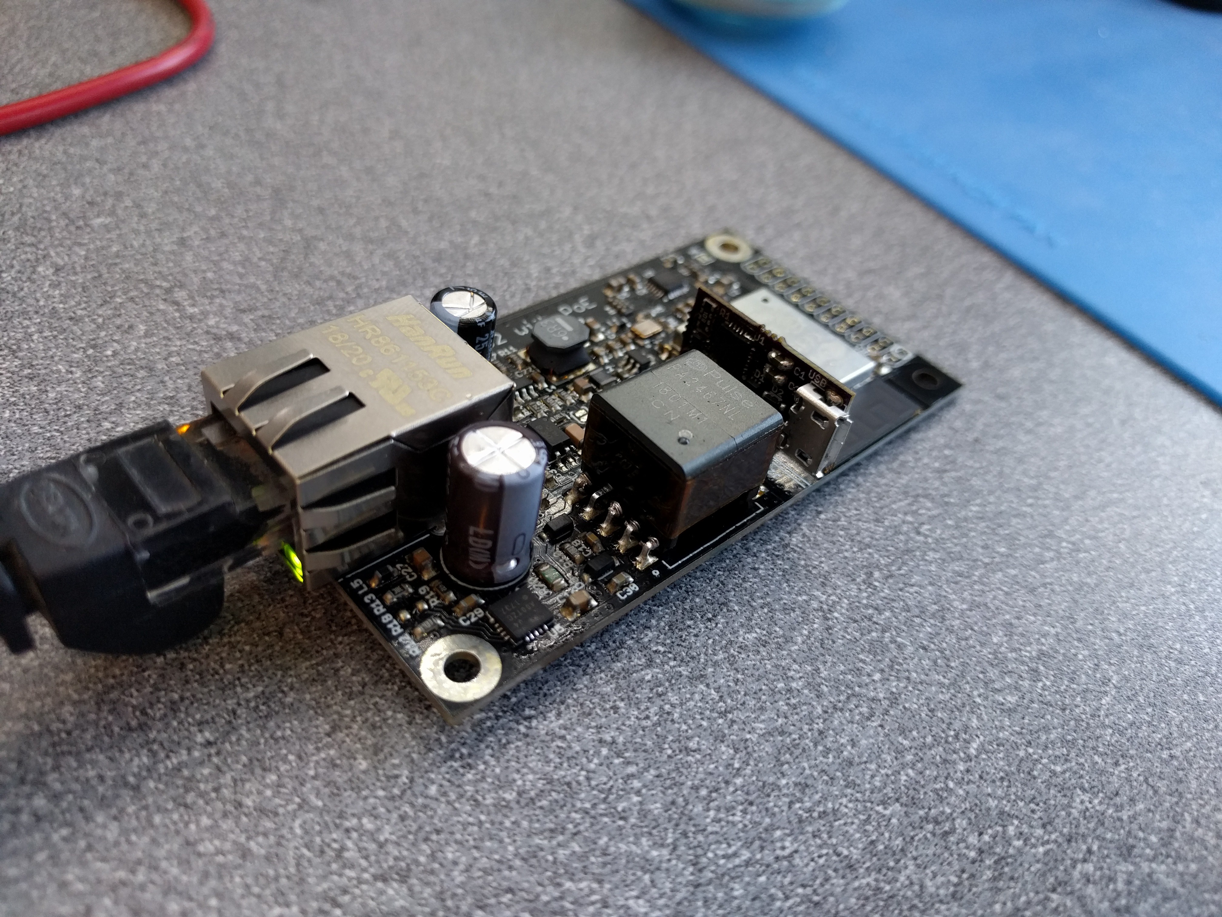
Initial tests are all positive: I can program the ESP32, the 12 V, 5 V and 3.3 V outputs are accurate, and after programming, the ESP32 connects to the network over Ethernet. I am now running a long term test of the unit under high load (13 W), which has been going for about 5 hours now. Performance of the production units seems to be equal to the prototypes.
Very happy with the progress!
-
Crowd Supply campaign ending!
11/12/2018 at 17:51 • 0 commentsThe Crowd Supply campaign has been going very well and will be ending soon, so if you haven't put in an order yet and you want one, now is the time! :)
I've been putting quite a bit of work into the software side of things during the campaign, to make it as easy as possible for anyone wanting to design something with this to get started.
First of all, there's now a web site at wesp32.com. It contains information on the hardware and on software development in different environments. Most importantly, it contains a link to the Product Brief, which is pretty much the go-to for all detailed information.
While the web site contains guidance on how to use the wESP32 with different development environments, there is now also a wESP32 demo code repository on Github, which contains full projects to get you started! At the time of writing it has the iperf Ethernet IDF code I used to get the performance numbers mentioned in my project logs, an ESP32-Arduino example to control a display from a web server, two simple MicroPython examples to control an LED light, one from a web server and one using Dweet.io, and a Mongoose OS demo that allows you to control an LED light very simply from an automatically generated web app!
If you take a look at these examples, you can see that most of them are quite simple and don't require much code at all. For instance, here's the LED control from Dweet.io code:
import machine
import time
import urequests

# Initialize light PWM, flash for 1/4 sec on boot
led = machine.Pin(23, machine.Pin.OUT)
ledpwm = machine.PWM(led)
ledpwm.freq(500)
time.sleep(0.25)
ledpwm.duty(0)

# Get the ESP32 unique ID as a string
uid = ''.join(['{:02x}'.format(x) for x in machine.unique_id()])

# Check dweet.io every two seconds to get and update the light level
while True:
  try:
    light_level = int(urequests.get(
        'https://dweet.io/get/latest/dweet/for/wesp32-light-demo-{}'
        .format(uid))
        .json()['with'][0]['content']['light'])
    ledpwm.duty(light_level)
    print ("Light level {}".format(light_level))
  except:
    pass
  time.sleep(2)
So if you thought the wESP32 was interesting but would be too hard to get started with, think again! There are still a couple of days left to change your mind and get your own wESP32 by backing my campaign! :)
-
Crowd Supply campaign now live
10/05/2018 at 21:40 • 0 commentsThe wESP32 Crowd Supply campaign is now live! I have parts for about 230 units in-house, so if you want one before the end of the year, at the time of writing there are less than 100 of those left! If you order later, they will ship from a new batch which is scheduled for February 2019.
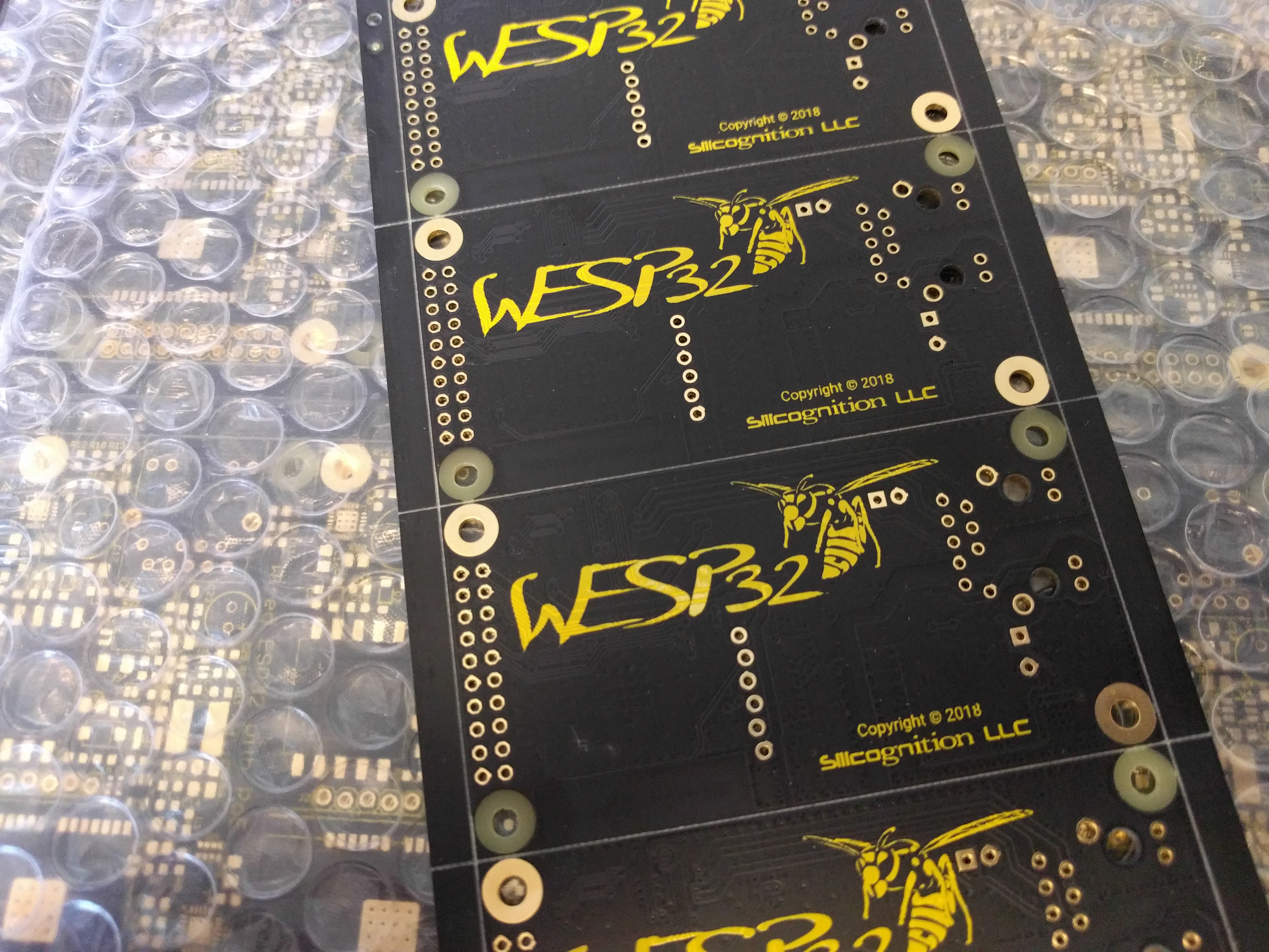
As I mentioned in the first campaign update on CS, I received the production PCB panels for the first batch:
![]()
I'm really pleased with how these turned out, my wasp is finally black and yellow as it should be. :)
-
Crowd Supply pre-campaign page live
09/05/2018 at 00:17 • 0 commentsThe wESP32 Crowd Supply pre-campaign page is now live!
Check it out and sign up if you want to be notified when the campaign goes live! There will be some early bird specials so signing up may land you a special deal. :)
-
Coming to Crowd Supply!
08/31/2018 at 18:43 • 0 commentsThe wESP32 is coming to Crowd Supply! After seeing how successful our #LiFePO4wered/Pi+ campaign was, it made sense to repeat the same thing for the wESP32. I hope to have the campaign up very soon now so you can start ordering!
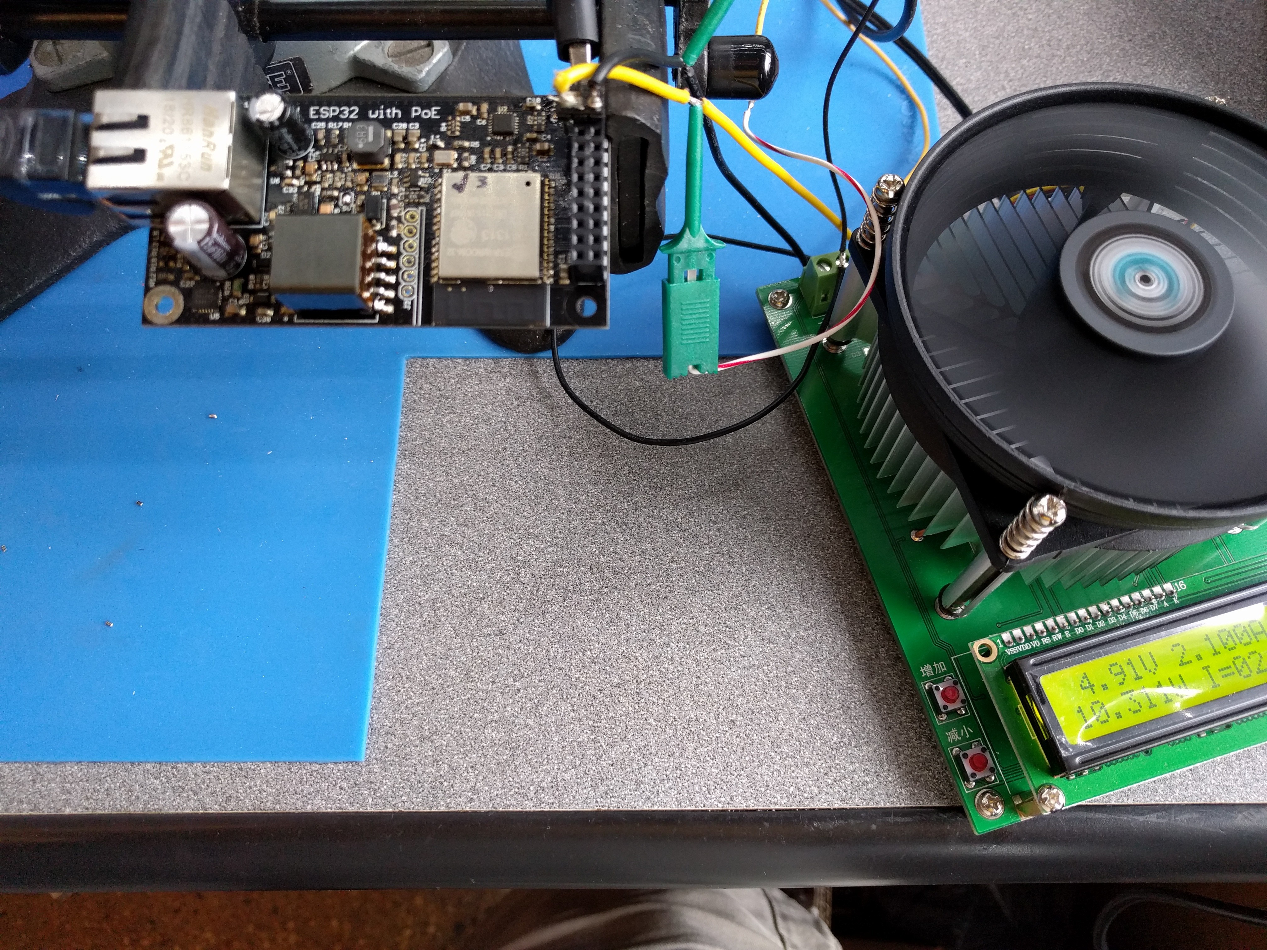
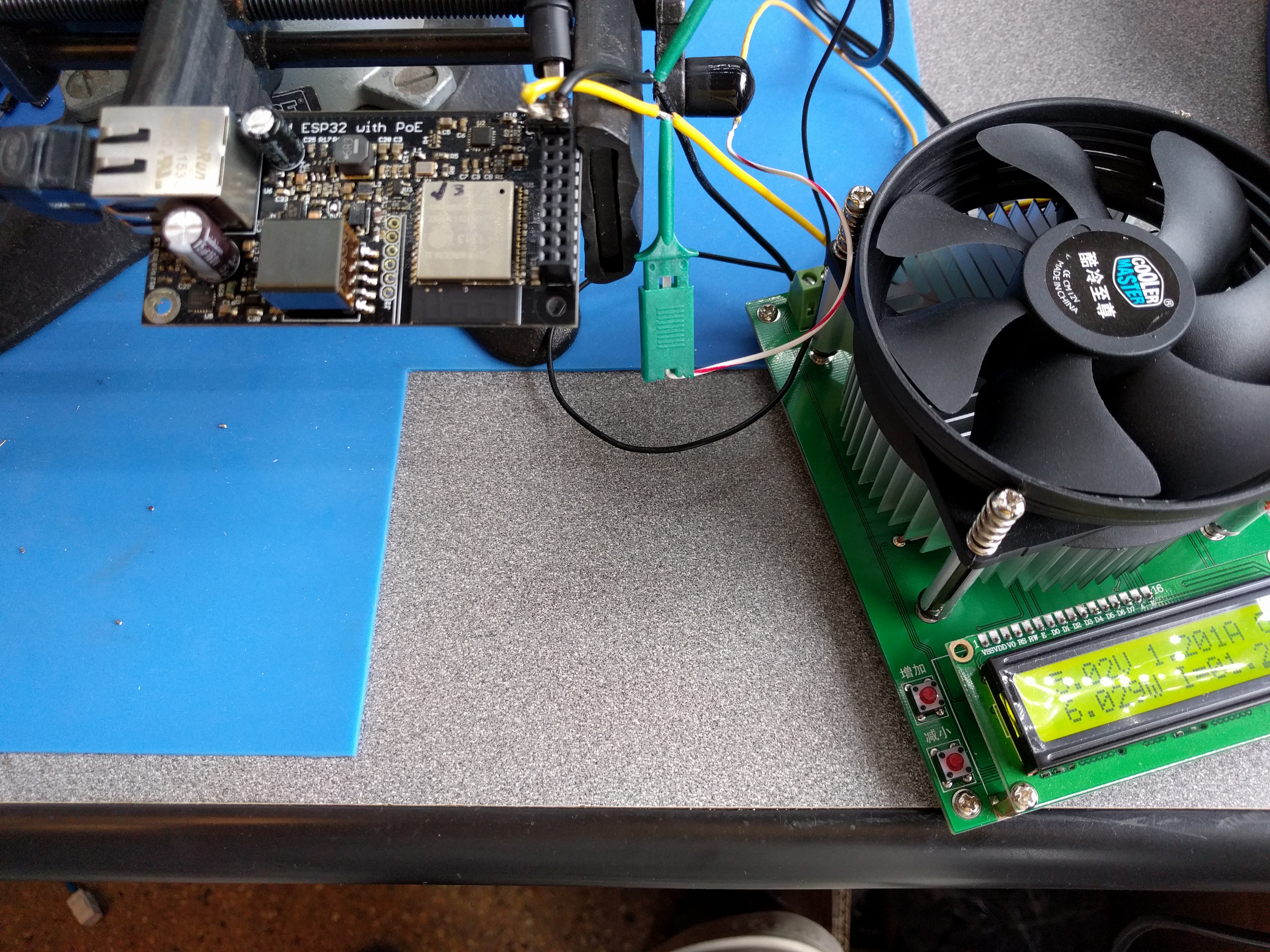
I've been very busy the past week with ordering boards, ordering components, and coming up with marketing materials. A campaign video is in the works, and we need demos to show off some cool stuff you can do with the wESP32. One simple idea was to make a "remote status display" you can send messages to:
You'd probably want a bigger screen for the real deal, but is conveys the idea. :)
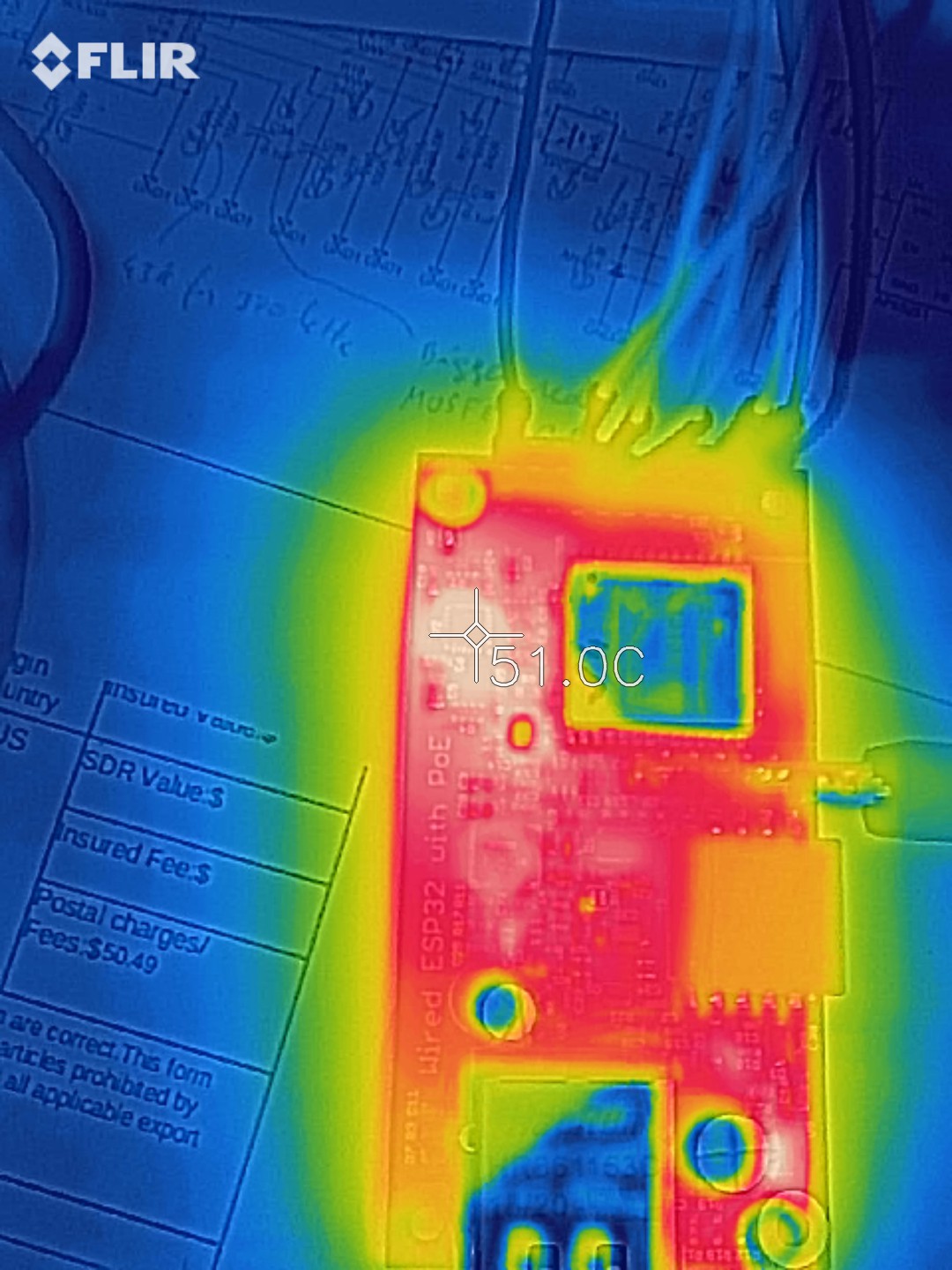
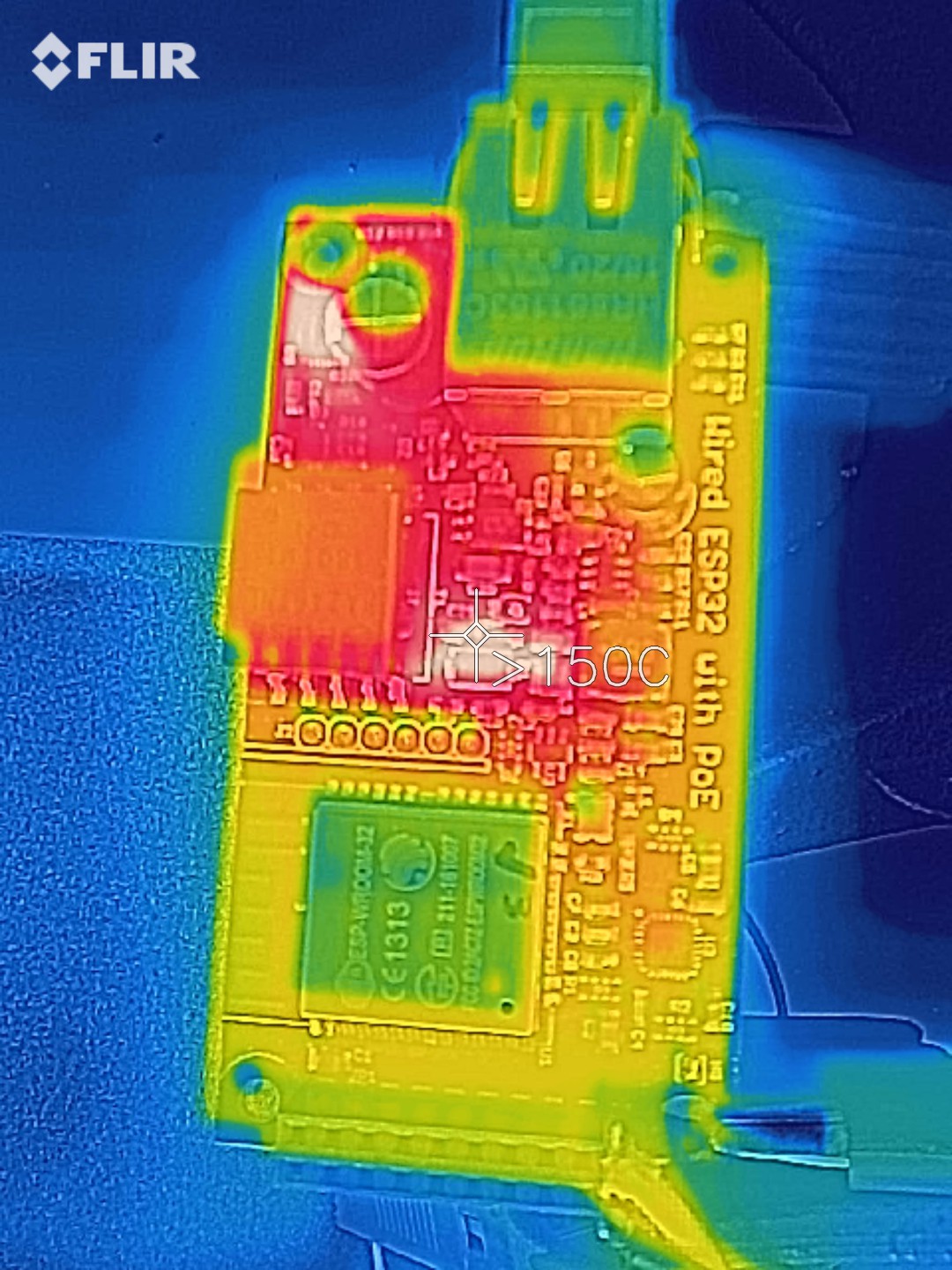
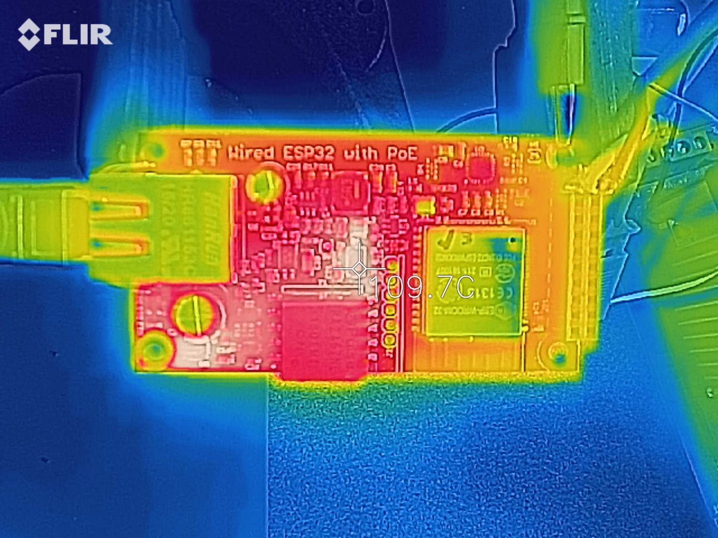
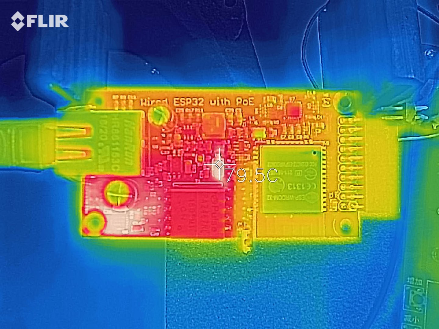
@martinschki had a good question in the comments: "How much heat do they emit under a low power application?" I've been doing tests and taking thermal pictures at high load, but I never thought of doing it for low loads! And in applications such as his where things get built into a wall this is important. So here's a thermal image under low load, running the demo shown above:
![]()
So it looks like the hottest thing on the board is the Ethernet phy chip. At 51°C I don't expect any problems for having it in a wall. But if you're going to use this to build an environmental sensor, you definitely need to keep this heat in mind when you design your device or your readings will be way off!
-
Final performance checks
08/21/2018 at 18:19 • 0 commentsI had left off my data performance testing last time wondering why the iperf UDP data rate was so low. Well, @aenertia on Twitter gave me a hint: you need to specify the amount of bandwidth you want to test on the client side, otherwise the UDP test defaults to 1 Mbit/s! So, just an average case of operator error. :) The iperf on ESP32 example code is too simple and doesn't provide / need this option, and I haven't played enough with this kind of stuff before to know things like that.
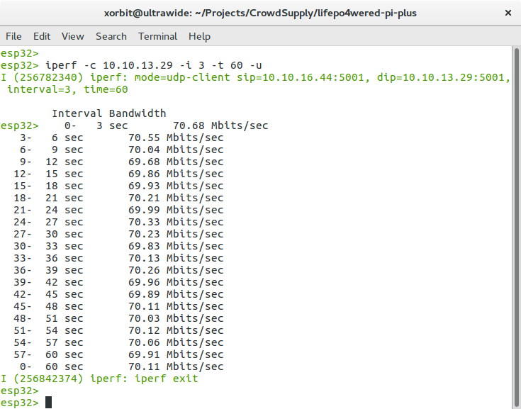
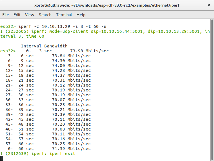
Here are the results for UDP when the wESP32 is the client (outgoing traffic):
![]()
Around 70 Mbit /s, nice!
So to test server, I used the following command on the client:
iperf -c 10.10.16.44 -i 3 -t 60 -u -b 100m
This sets the target bendwidth to 100 MBit/s.
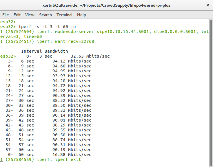
Here are the results for UDP when the wESP32 is the server (incoming traffic):
![]()
Wow, >90 Mbit/s! That's close to the theoretical maximum!
Now I'm pretty sure that from the moment the ESP32 would start to do anything with this data other than throw it away, the data rate would go down, but it's still nice to see that the Ethernet data system as implemented on the wESP32 performs very well.
One last thing left on my list to validate the design was to test power performance when the 5V power option is selected by bridging the solder jumper. As mentioned before, the whole power system is optimized for 12V power, and the 5V option was a little bit of an afterthought but it could be useful to many people. So how does it do?
In my first test I was really pushing it:
![]()
![]()
Trying to push >2A through a power path that was designed for 1A: not a good idea. That poor diode was frying, but it lived. So, intermittent 10W may be possible at 5V, but don't run it like this continuously.
Here's a more moderate test:
![]()
![]()
That's better. At 6W output (1.2A), the diode temperature isn't so bad. Still, when running at 5V, your continuous average load should probably be kept below 5W.
These results are fine though. If you need high power, use 12V. It keeps the currents much more reasonable. If you really need high power at 5V, add your own buck converter. The on-board option for 5V will likely still be very useful for the majority of people who need 5V in their system though. 5V sensors, keypads, displays, etc. usually don't need that much power.
-
More data performance
08/19/2018 at 05:14 • 3 commentsAfter I posted the previous log, I kept working on trying to figure out the data rate figures, the worrying one being iperf performance when the wESP32 was the server, which was really poor.
Taking a step back, the reason I was doing these tests in the first place was to validate the hardware. Before I go to production, I need to have confidence that the design is sound, and in the case of this test, that there aren't any circuit or layout issues that are making the signal path performance poor, such as interference from the PoE power system or impedance mismatches causing reflections and affecting the signal to noise ratio. Such issues would result in high packet loss, making retransmission necessary, which in turn is observed by poor data rates.
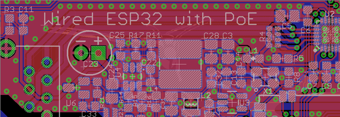
So from the previous tests, it looked like the outgoing signal path had been validated as working well (iperf client), but the incoming signal path was suspect (iperf server). So I started looking at the layout to see if there was anything obviously different between the incoming and outgoing signal paths. Not really, both the TXP/TXN and RXP/RXN were laid out as impedance matched differential pairs. In the picture below, you can see them as the 4 fatter traces under the "Wired ESP32 with PoE" writing:
![]()
While I was perusing the LAN8720A phy datasheet to see which pair was suspect, I looked at the "Architectural Overview" block diagram on page 5, and I noticed something I had forgotten: that this chip implements "Auto-MDIX", a feature that automatically switches the TXP/TXN and RXP/RXN pairs as required to work correctly with either straight or crossover Ethernet cables.
This gave me an idea: if I used a crossover cable, the incoming and outgoing data would switch on which differential pairs they were travelling, and the phy would internally switch them back so things would still work. If the problem moved from incoming to outgoing when I did this, then I'd know one of the data pairs was performing poorly. If nothing changed, and the performance on the outgoing data test was still good, I'd know both data pairs were performing well.
After locating a crossover cable, I ran the test, and the results were identical to the ones from the test with the straight cable. This means both data pairs are performing equally well and the data path is sound! Yay! :)
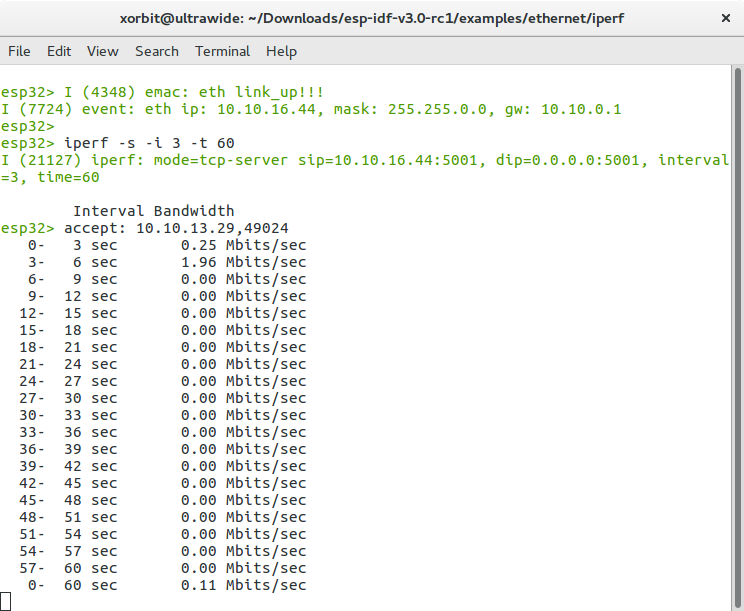
So, the question remained: why was the iperf server test working so poorly? Even though I had pretty much validated the hardware, this still bugged me so I kept trying to see if I could figure out the issue. I decided to play with some of the settings offered in 'make menuconfig'. In the process of doing this, at some point I got the client performance to >80 Mbit/s, but the server performance remained poor. Eventually I did find something that made the TCP test work: the option "CONFIG_EMAC_L2_TO_L3_RX_BUF_MODE".
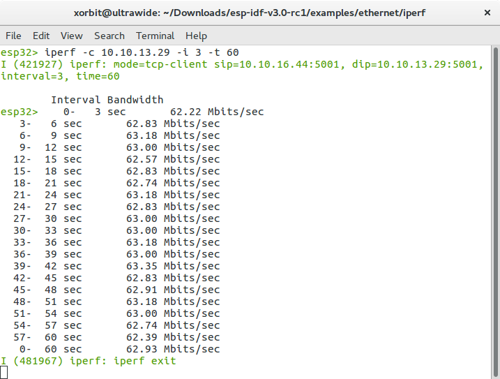
The docs explain that "when Ethernet MAC doesn’t have any unused buffers left, it will drop incoming packets (flow control may help with this problem, to some extent)". Still, the docs recommend to keep this turned off if unsure, because it involves copying data instead of passing pointers, which decreases performance. Still, the iperf test was apparently running into the problem that the MAC didn't have buffers left, because turning it on made a big difference. Here are the results of the iperf client test with this config:
![]()
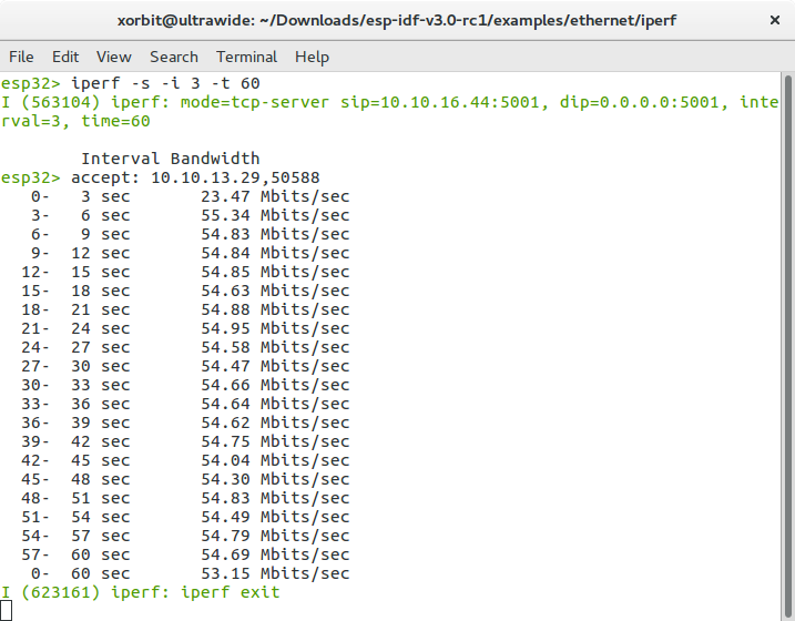
And here are the results of the server test, which now performs well:
![]()
That's when testing with TCP. Oddly, the UDP server test still performs very poorly: I only get around 1 Mbps.
Obviously, this is some other configuration issue. Since TCP was working well, I called it a day.
Overall, I'm very happy with the performance of these first prototypes: the power output beats my expectations and the spec, the attainable data rate is very good and beats my expectations as well. With these prototypes working as well as they do, this design is ready to go to production! Most components are on order already. Stay tuned!
-
Data performance
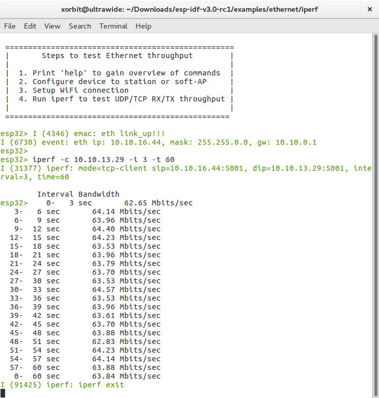
08/17/2018 at 18:41 • 0 commentsAfter confirming the PoE power subsystem performance, I wanted to make sure that the data path was sound as well. To do this, I needed some performance test. The ESP-IDF contains an iperf example for WiFi, but there isn't any for Ethernet. So I decided to try and hack the Ethernet example and the WiFi iperf together. It's messy and ugly, but eventually I got it to work. Here are the test results:
![]()
Around 63-64 Mbit/s, not too shabby for a little chip! Of course I don't really have much to compare to. Anyone have any numbers on how much speed can be expected from an Ethernet connected ESP32?
The first test was in TCP mode. Then I tried the same thing in UDP mode:
![]()
Wow, more than 70 Mbit/s, even better!
Then I decided to try the ESP32 as a server instead of client:
![]()
Whaaa? That's just weird, something seems wrong. Anyone have any idea why this would happen?
-
Initial test results
08/02/2018 at 03:16 • 1 commentInitial test results are in!
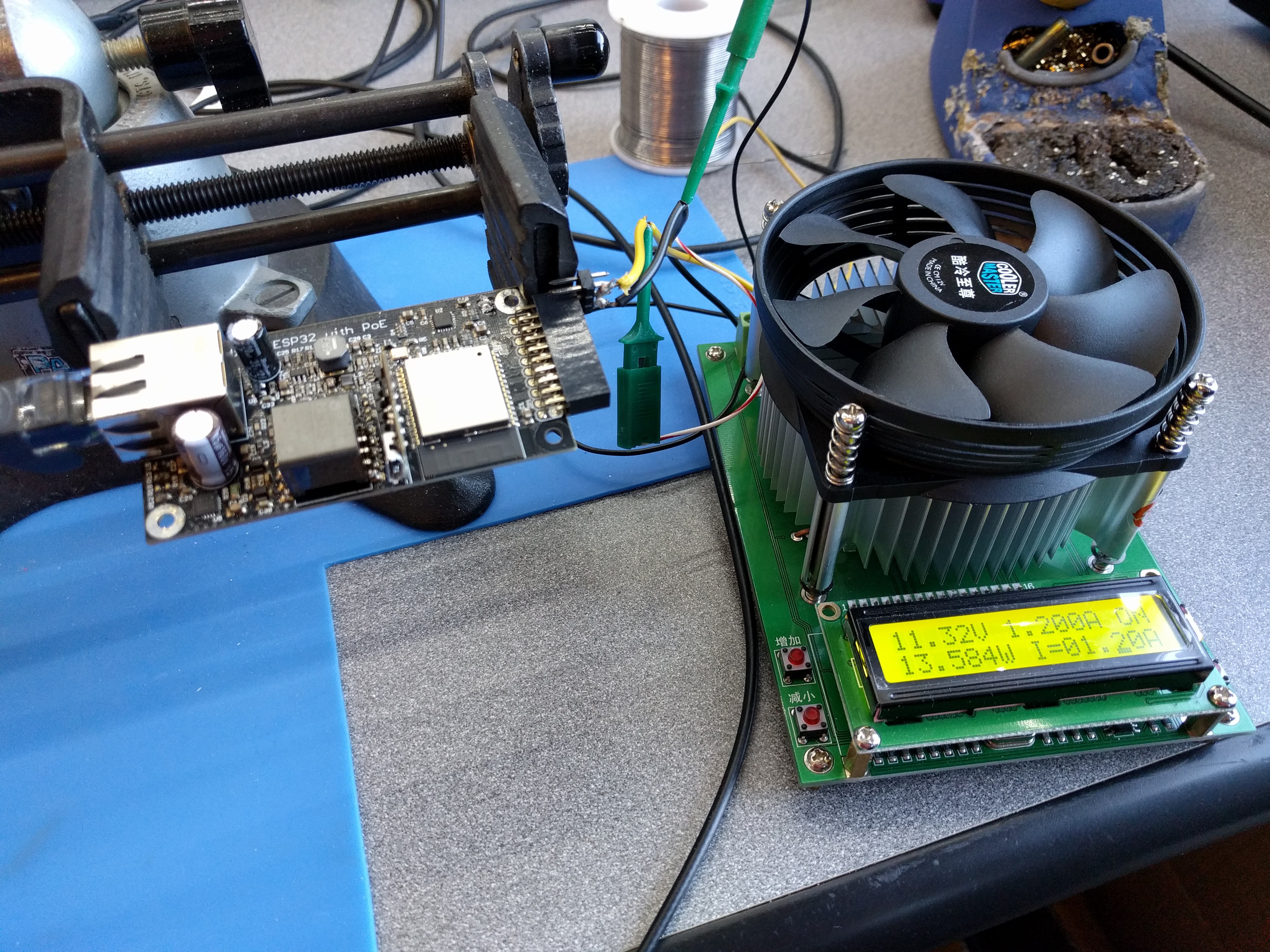
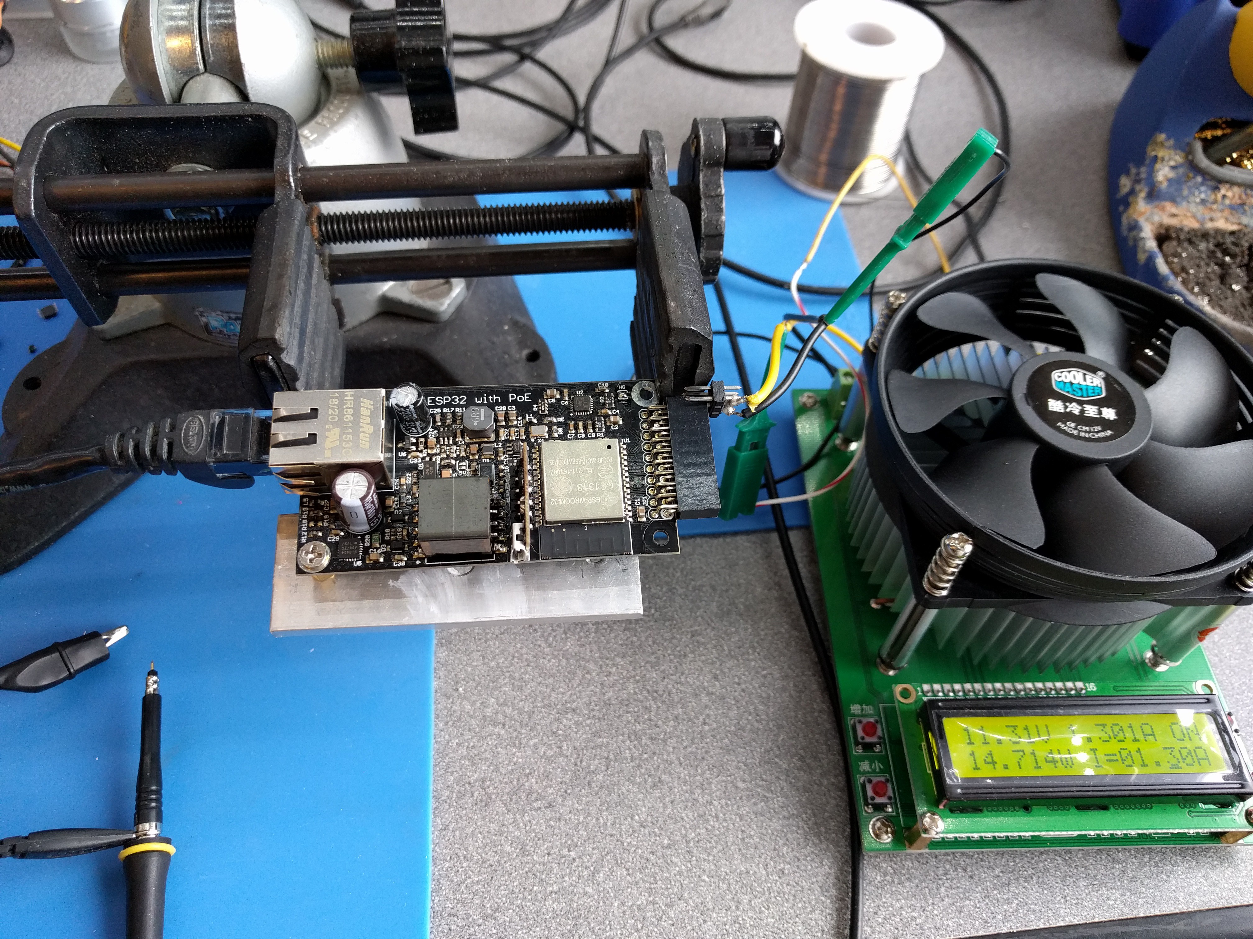
I used my electronic load to see if the wESP32 prototypes would achieve my target of 12.95W output power to meet the 802.3at Type 1 PoE specification. Here's my setup:
![]()
Yes, you are seeing that correctly on the display of the electronic load: 13.5W! What's more, I kept it running like this for a couple of hours and it was stable! No over current or thermal shutdown. And this is without any heat sink attached to the mounting hole! I never expected I would get full target power without extra heat sinking.
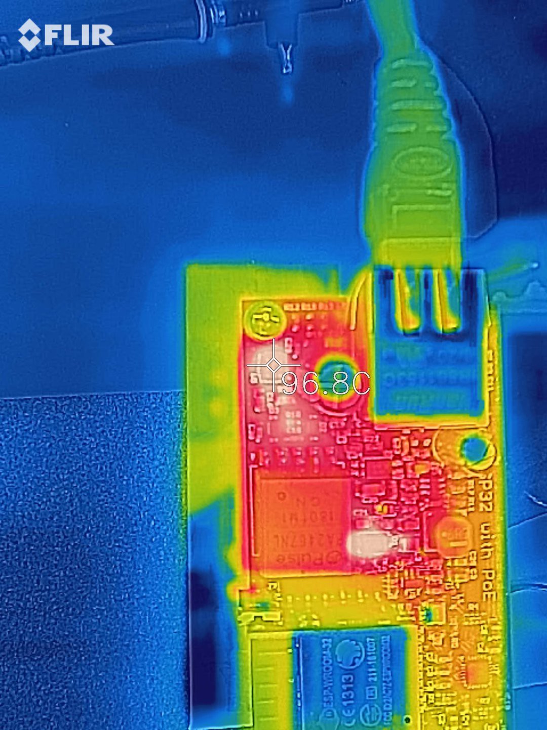
The hot spots are as expected the Si3404A PoE power converter chip and the secondary side Schottky rectifying diode. The diode is hot, but it's within acceptable limits:
![]()
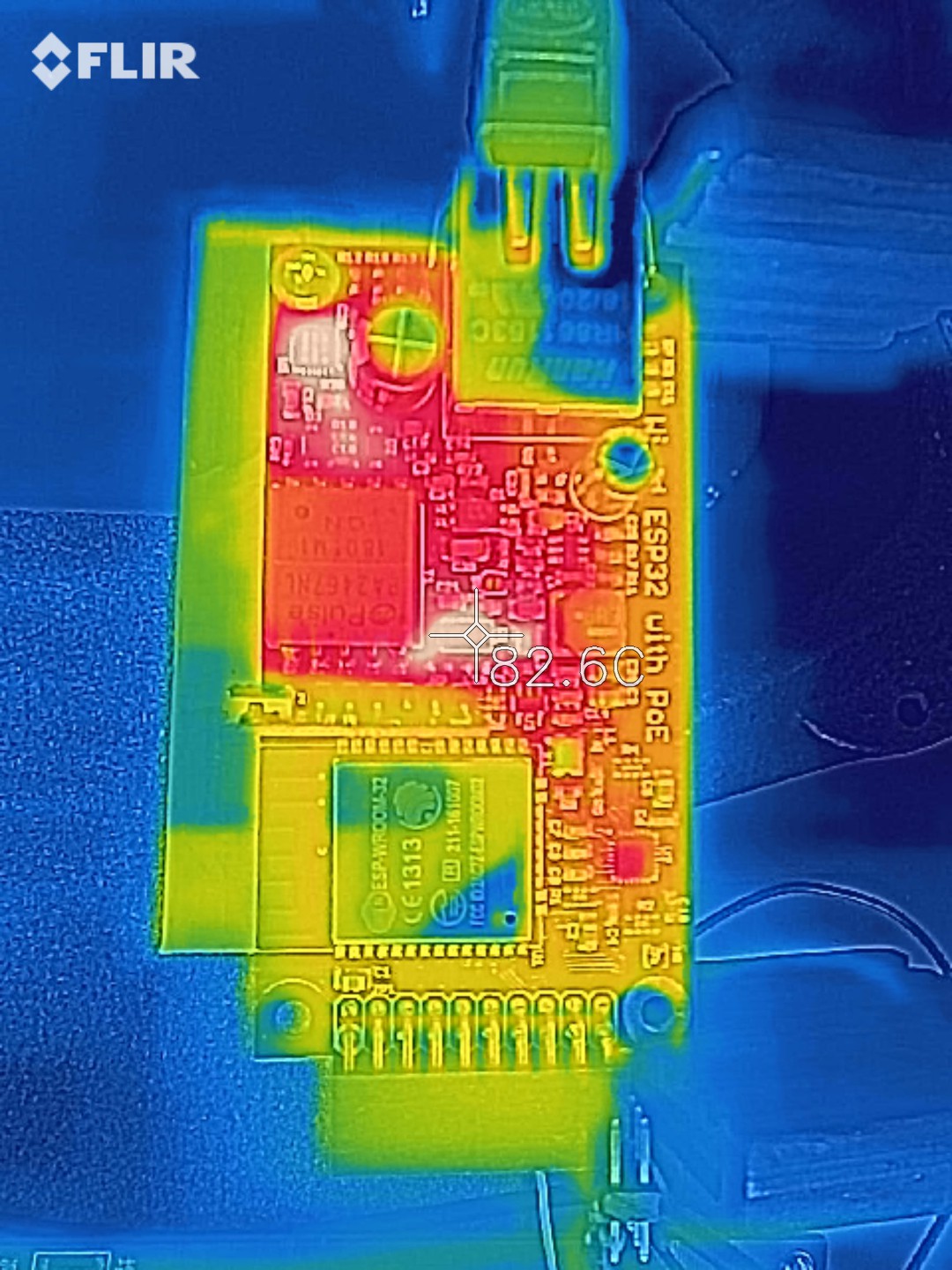
The power chip is getting much hotter, not enough to trigger over temperature protection apparently, but too hot to run like this for a long time:
![]()
Although it works, I would not recommend running at full power without any heat sinking. So how much difference does connecting a heat sink to the mounting hole actually make? Let's find out:
![]()
It may be noted that I'm not trying very hard here to provide an optimal heat sink. I'm just using a flat piece of aluminum with a stand-off screwed into it, screwed to the mounting hole. No thermal grease is used.
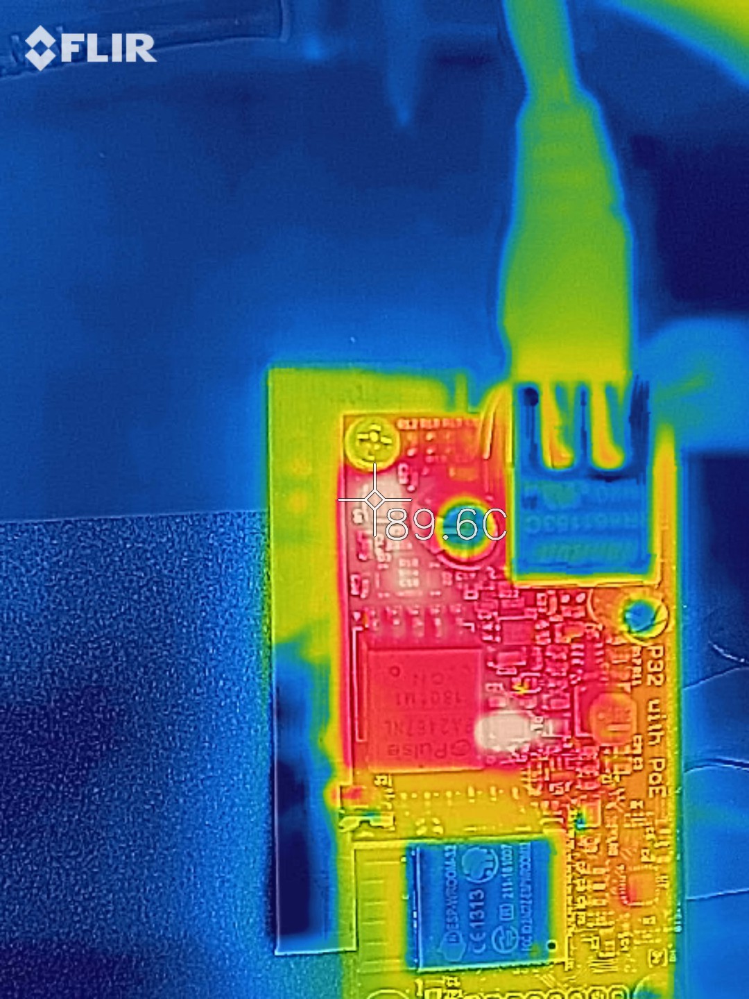
As you can see, I decided to really push it and bumped power up to 14.7W. This was stable with the extra heat sinking. Of course, the diode got a little hotter now:
![]()
Still perfectly acceptable. The power chip on the other hand is cooler now, because the heat sink is doing its job pulling heat away from the chip:
![]()
I decided that to compare apples to apples, I better reduce the output load to the same 13.5W as before so I could see how much difference in temperature the heat sink actually makes:
![]()
That's 25°C cooler, at an acceptable temperature while running at a load that's higher than demanded by the spec. I call that good enough. :)
An interesting detail in the latter thermal images: the resolution is good enough to see a couple more small hot spots: one by current sense resistor R20 and one by resistor R10 of the RCD clamp. Both are normal and expected: the current sense resistor senses the current through the primary winding and will dissipate around 0.1W under high load, while the RCD clamp is there to dissipate energy from self-inductance of the primary flyback winding, to prevent this energy from resonating and producing large (noisy and potentially damaging) voltage spikes.
It should be noted that in all these tests the actual load is a little higher than what I see on the electronic load display because the 3.3V buck converter, ESP32 and Ethernet Phy consume some power as well. But I decided to ignore it for these tests since it's less than 0.5W or so.
So how does the flyback converter's output power look? How much noise is on it under various loads? I had planned to show some scope traces, but I decided against it because they were very boring: just a flat line. :) That's excellent! Even under the highest load, the V+ power bus looks very clean. I haven't had this design tested for EMI but if/when I do, it looks like it may be fine.
Very happy with these results. Next, I need to check what happens when 5V output is selected, and try to figure out what's wrong with the two prototypes that aren't fully functional, plus build some more prototypes for the people who are waiting to buy them for their own testing.
-
Prototypes... built and tested!
07/28/2018 at 04:30 • 5 commentsI found time to build four wESP32 prototypes yesterday! Here are some shots taken during the (manual) assembly process.
Stencil with board ready to be pasted:
![]()
Boards with solder paste, ready for assembly:
![]()
Most components placed:
![]()
After reflow:
![]()
All boards needed some touch up, my solder pasting was kinda messy with the frameless stencil and the old paste, so there was some bridging on the QFNs that needed to be fixed up.
Then after I completed the assembly of the first prototype I plugged in the PoE Ethernet jack and immediately measured 11.4V on the V+ rail! Yay, what a relief! :) The PoE section seems to be immediately operational. I had some trouble programming the ESP32 using the ESP32-Prog submodule though. Switched to a different prototype I finished up, and on that one I could program the ESP32 right away! So I loaded the ESP-IDF Ethernet example and plugged it in:
![]()
Behold, blinking LEDs on the Ethernet jack and a sure sign of success! Checking the serial monitor, I could tell the device was successfully getting an IP address from DHCP as well. :)
This is what has been verified to work so far on some of these prototypes:
- PoE produces 11.4V on the V+ rail, and 5.1V when the 5V solder bridge is closed.
- Buck converter produces 3.3V to power the ESP32 and Phy.
- Ethernet Phy is operational and communicates with the ESP32, tested to the point of getting an IP address from DHCP.
- ESP32-Prog submodule and on-board logic manages the EN and IO0 signal correctly to allow programming, serial monitoring and 50MHz EMAC clock to work correctly.
I have two prototypes where all the above works, a third seems to work but for unknown reason it is not getting an IP address from DHCP, and on the fourth I can't seem to program the ESP32 yet. Still work to do to get those going but it seems likely these are just assembly issues and not a problem with the design. Let's hope.
More testing is still needed to make sure the design is sound:
- Check the power supplies and see how noisy they are, optimize snubbers and filters in the flyback stage to minimize noise and optimize the EMC.
- Check how much power can be pulled from the PoE with and without a heat sink attached. See if we get to 12.95W which is the target for 802.3af (802.3at Type 1). I hope to get there with a heat sink, but expect a lower maximum when no heat sink is used.
- Check how much power we can pull when the 5V option is selected. I'm not expecting to reach 12.95W here, since the flyback is optimized for 12V.
- Check if we have enough power and good enough signal with really long cables (does anyone know if there is a way to get a signal qualify figure from the phy?).
- Check how much power is available from the 3.3V rail for the specification.
wESP32: Wired ESP32 with Ethernet and PoE
A low cost ESP32 core board with Ethernet and PoE for convenient "single cable" deployments