Patrick Van Oosterwijck
-
ESP32-Prog prototype
07/25/2018 at 23:27 • 0 commentsThe last three months have been absolutely crazy. Between vacation, selling a house, buying a house, remodelling 4 bedrooms, moving, visits by family and friends, an audit, and getting the #LiFePO4wered/Pi+ Crowd Supply campaign going, I've had very little time to work on the wESP32 unfortunately.
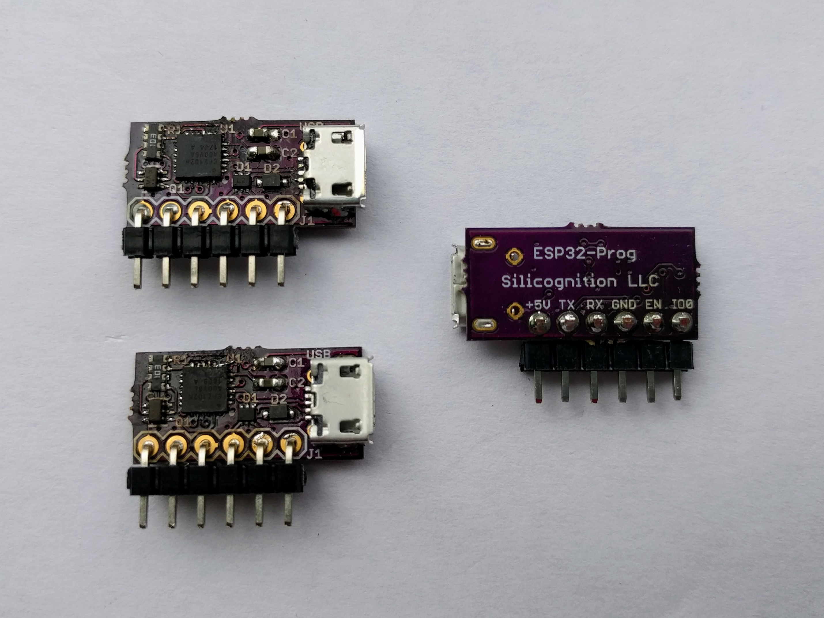
So I'm relieved that I finally found some time to relax and work on some electronics! Here's the result: I built 3 ESP32-Prog prototype modules for the wESP32:
![]()
They are built manually with the hot air rework station so they're a little messy, but they seem to work! After adding a little patch wire that is. It's nearly impossible to see, but on the top right corner of the CP2102N, I forgot the connection between pins 7 and 8. So dumb: Eagle told me clearly there was an air wire left and I completely missed it.
I tested them by connecting them to my PC and /dev/ttyUSB0 showed up. Then I ran:
screen /dev/ttyUSB0 115200and when I connected TX to RX, the characters I typed were echoed back. What I haven't tested yet is whether the EN and IO0 management circuitry works.
I have all the parts to build wESP32 protos as well, but I'm doing that one the "proper" way with solder paste, a stencil and reflow oven. Hopefully later this week!
-
Ethernet jacks
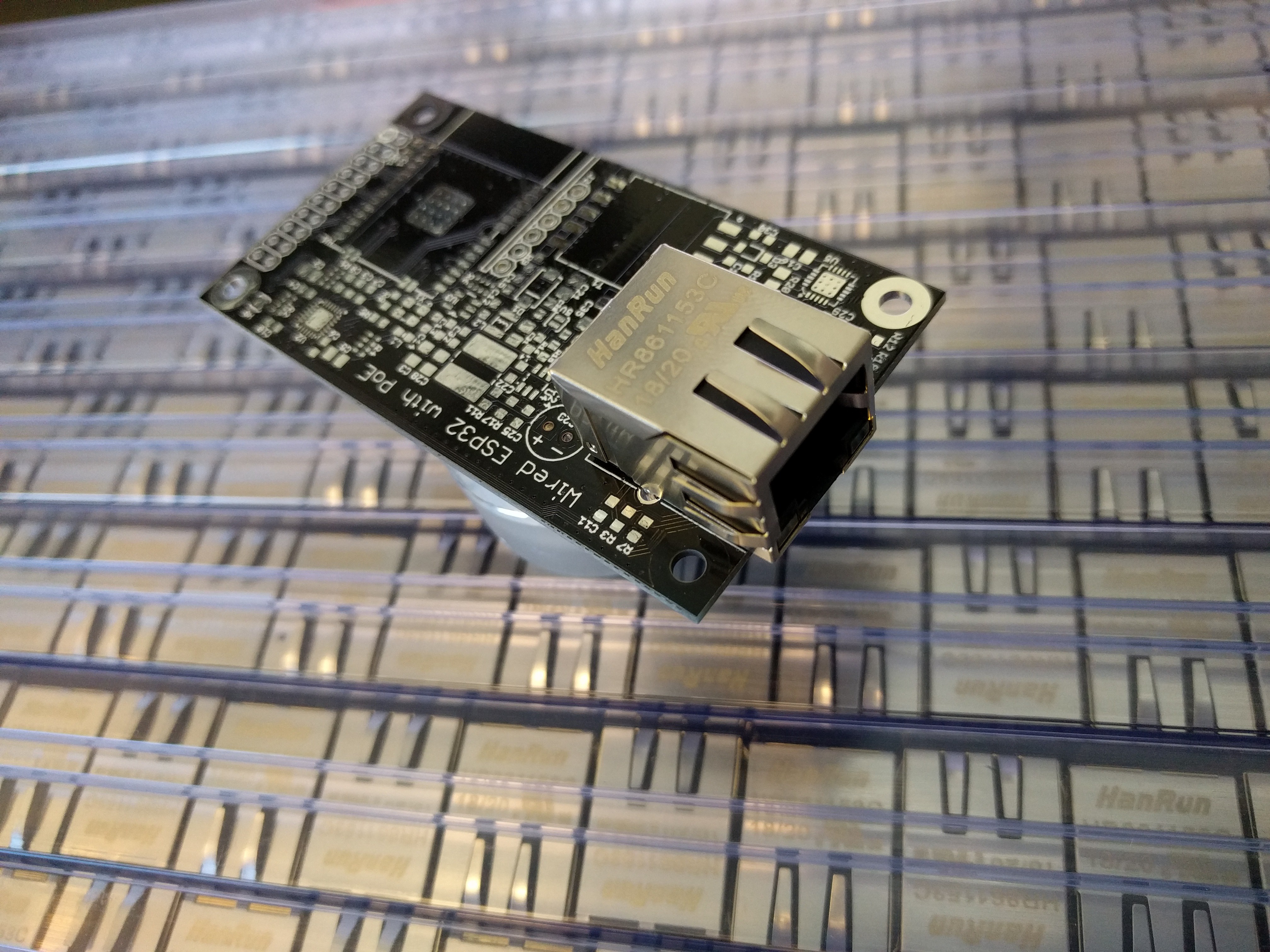
06/21/2018 at 20:05 • 11 commentsBack from vacation and finally more or less caught up. My Ethernet jacks arrived from Hanrun while I was away, 250 of them. A quick check shows that luckily, they seem to fit my footprint:
![]()
That's a relief! :)
I've also been creating the BOM and crunching some numbers on pricing to get a better idea of what the BOM cost and COGS might be, and unfortunately it's higher than what I had been guessing. Bottom line is that with the numbers I see, in low quantities this is likely going to be a ~$45 board to make it worth my while. I know that's a lot more than most ESP32 boards, but usually the only "expensive" part on those is the ESP32 module. Compared to other "normal" ESP32 boards, the Ethernet jack and phy add a good amount of cost, and the PoE power components like the PD chip and flyback add even more.
So now the question is: would you still be interested in buying this board at that price? Please comment!
-
Proto PCBs arrived!
05/18/2018 at 15:33 • 4 commentsFirst of all: terribly disappointed that my project didn't make it to the next round of the Hackaday Prize. I tried really hard this time, checked all the check boxes they demanded... except I didn't make a hokey video in which I explain how great my stuff is I guess. Congrats to the projects that went through, most very deservedly, others, less so... I don't think rotary encoders are a particularly hard problem to solve for instance, but let's leave it at that.
This project will continue with or without the funding from Hackaday of course. Maybe a little slower since my focus needs to be on things that let me eat instead, but it will happen.
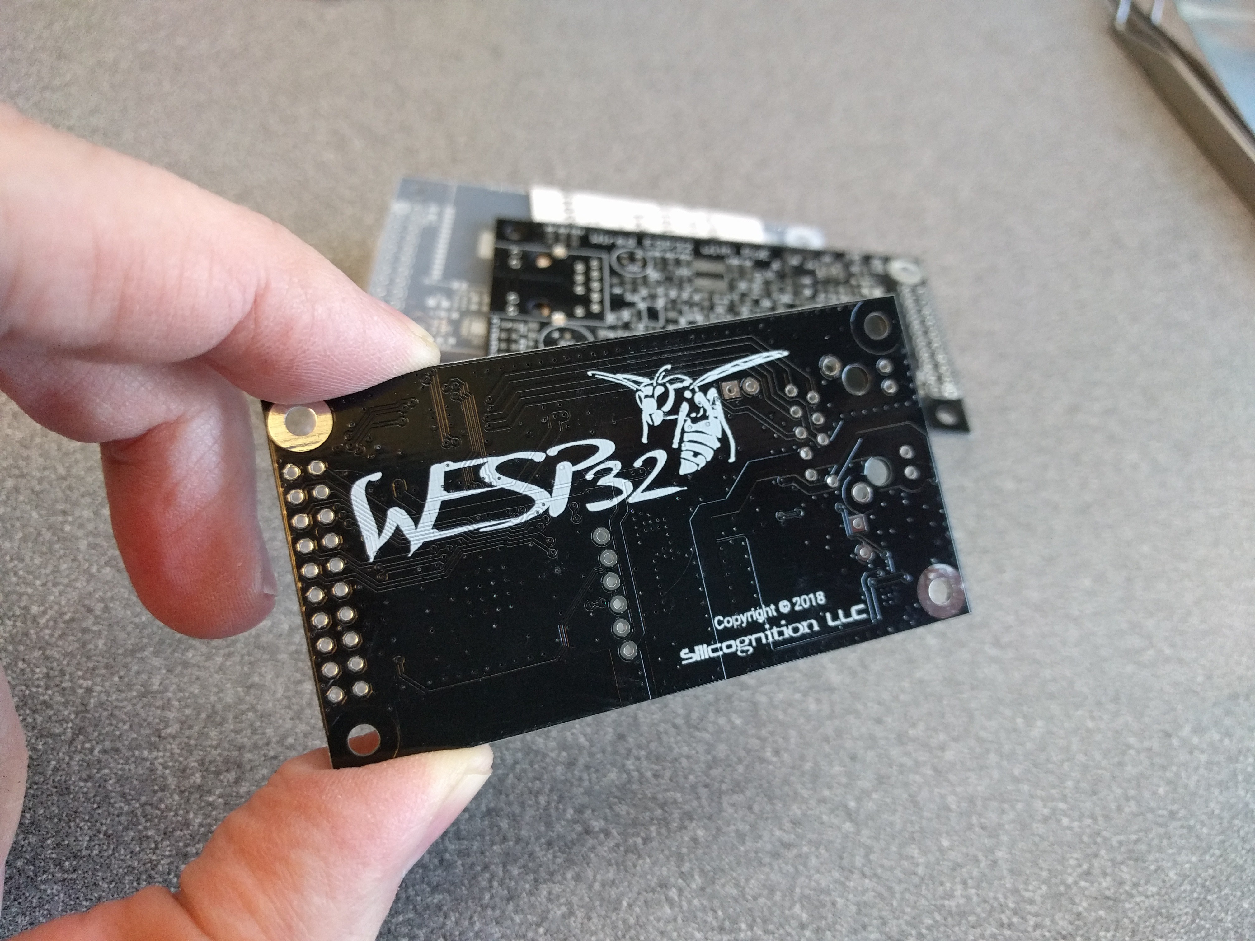
As for progress to report, I received PCBs and a stencil from Elecrow:
![]()
They came out nice, the logo printed well in silkscreen and really "pops". The white on black is looking good. As I said before, I would likely target yellow on black for production boards, any opinions on that?
Still waiting on the PoE Ethernet jacks from China, they will likely only arrive during my vacation, which is going to push any built-up prototypes well into the second part of June. Let's hope they'll work right away! :)
-
Schematics!
04/20/2018 at 19:07 • 1 commentSchematic PDFs are now available on the main project page if you want to see what makes this thing tick!
The ESP32-Prog-1.pdf file documents the ESP32 programming submodule. It's a straightforward CP2102N based design with automatic EN and IO0 control circuitry, optimized for size by using TVS, transistor and resistor arrays instead of discrete components. Note that pullups for EN and IO0 and the EN capacitor are not on this board but on the main board instead, since they need to be present on the main board whether the programmer is connected or not.
The wESP32-1.pdf file has the main board schematic, and there's much more to that one. The top left has the Ethernet jack and phy, below that is the PoE power supply, top right is the ESP-WROOM-32 module, below that the EN and IO0 control circuitry and on the bottom right the 3.3V buck converter and 20-pin IO header.
The Hanrun HR861153C Ethernet jack has LEDs, magnetics, Bob Smith cable terminations and PoE diode bridges built-in, and this high level of integration is very helpful in keeping the board compact. The phy is a LAN8720A connected to the ESP32 via RMII, with resistor straps configured for full 10/100 capability.
The PoE power supply is optimized for 12V output (with 5V optional), and is based on the highly integrated Si3404-A PoE PD and PWM. It is configured in a fully isolated flyback topology. You may note that some component values are missing here, specifically those related to loop compensation and snubbers. The reason for this is that these values have to be optimized based on measurements that can only be obtained once I have working prototypes, as they are very dependent on flyback transformer and layout parasitics. It is likely that not all these components are needed, but experience with my other PoE project has taught me that it's better to allocate space for all components that might be needed than to regret not having them. I added a lot of filtering on the secondary side to improve my chances of having nice and clean power, since I witnessed quite a lot of noise on my other PoE project. A simple buck converter rounds out the power system to generate the 3.3V for the ESP32, phy and other connected circuitry.
The EN/IO0 circuitry is modelled after that on the Olimex ESP32-GATEWAY and is needed because of the many possible states of the IO0 line. It needs to work correctly to trigger programming mode or UART terminal on boot, and it is also used as the clock input for the Ethernet MAC so this clock has to be activated after the ESP32 has determined boot mode.
-
Layout DONE!
04/18/2018 at 17:30 • 8 commentsThe rev 1 layout is done! It will be highly disappointing to many people. Not only was it not designed to wear around your neck (although I'm sure enterprising hackers could make that work), but it does not contain ten million LEDs either! In fact, there aren't any LEDs on it at all!
I don't know what I was thinking when I created this abomination. How am I expecting to get any attention at all for this project without covering it with LEDs? Insane. Here I am thinking about mundane and boring concerns like power conversion efficiency, EMI, snubbers, transmission line differential impedance, ground plane preservation and manufacturability, while I completely forgot about the first and foremost raison d'être for any electronic project: flashing LEDs.
I pretty much submitted it to the Hackaday Prize for nothing since no judge will ever bother to look at it. Especially not since I will likely not bother to make a flashy video either to explain why this thing is cool even without any flashing LEDs. I must be insane if I expect people to read instead.
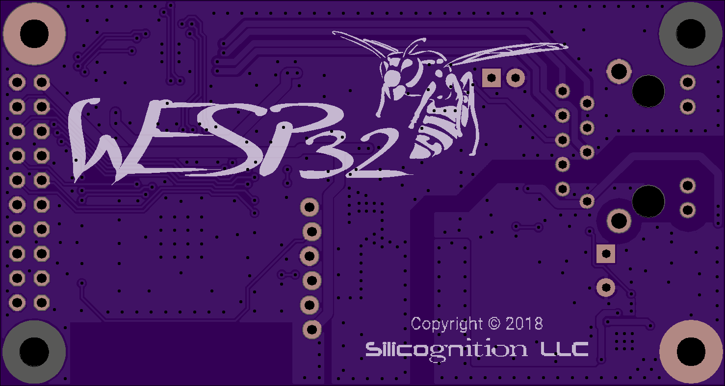
Well, at least I came up with a pretty slick logo that may help grab some eyeballs, so all may not be lost:
![]()
Yes, I do know how to spell "wasp", but I am a native Dutch speaker so I couldn't help myself. And you have to admit that it looks kinda badass. :)
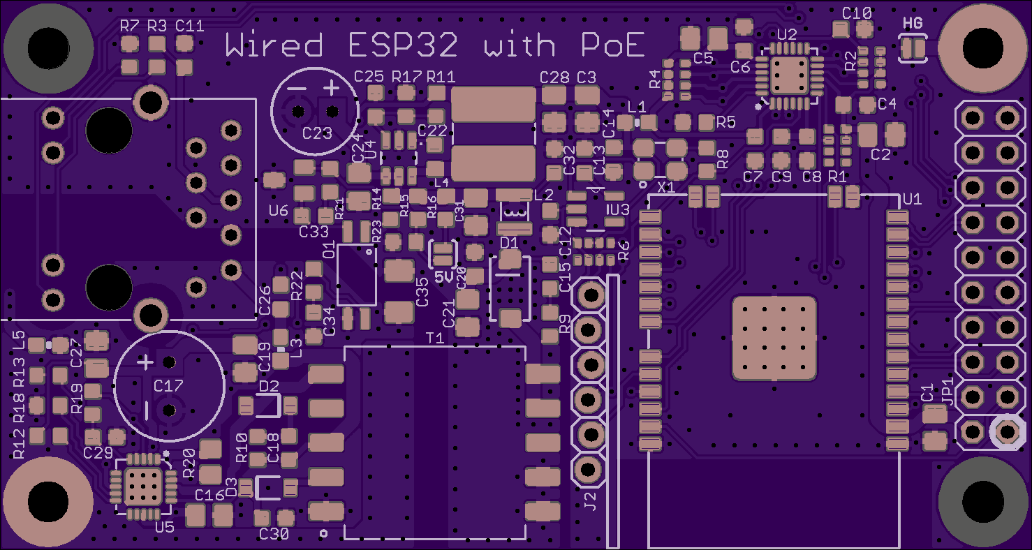
Final version should probably have a black background with yellow silkscreen, but OSHPark PCB renderings look really nice for showing the finished look of a board, so we'll go with a white/purple wasp for now. Here's the component side:
![]()
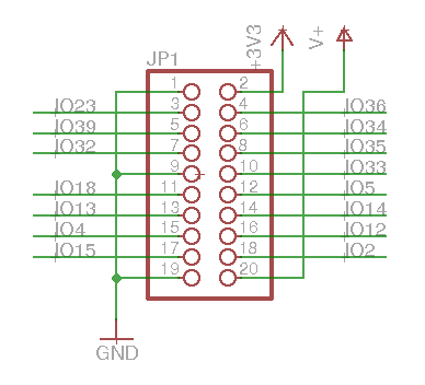
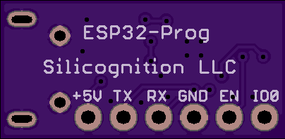
I managed to cram it all into 75 x 40 mm. The header in the middle is where the ESP32-Prog sub module can be installed for programming and/or USB serial terminal. I also added a solder jumper to allow you to select 5V power output instead of 12V. I'll have to wait until I can do testing to see how well this will work. The flyback transformer turns ratio is optimized for 12V output, but even if I can't get to the full 13W output power when the 5V option is selected, it likely still is a very useful feature to have. The header on the right side is where you connect your application board. It gives access to V+ (12V or 5V), 3.3V, 3 GNDs and 15 ESP32 GPIOs. Here is the pinout (pin 1 is marked with a fat circle on the PCB):
![]()
On the left side of the PCB is the Ethernet jack where you plug in the single power/network Cat5 cable. Oh wait, I guess I lied: this board does have LEDs, there are two built in to the Ethernet jack!
If everything works as expected, you should be able to get >12W out of the 12V power output. 12 watts! Imagine how many flashing LEDs you'll be able to power with that! :)
Hackaday Prize round 1 is almost over so please, if you haven't done so already, give my project a like here so I can collect some more seed funding from Supply Frame! Thanks!
-
Progress: floorplan, some layout
04/10/2018 at 21:00 • 0 commentsI find laying out boards too much fun. It's like a giant puzzle that slowly comes together, with difficult conflicting constraints but also freedom to find creative solutions. You start with a concept and a giant mess of parts and slowly it crystallizes into a beautiful reality. I think I'm addicted to laying out boards. ;)
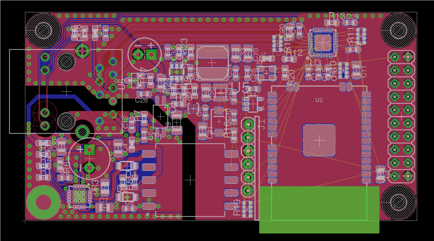
Anyway, while I should be spending most of my time writing documentation and finishing the test fixture for the #LiFePO4wered/Pi+, instead I've been working on figuring out the floor plan puzzle for the wESP32 instead. And of course, you need to actually lay some parts out to determine if it will work. Here is the result so far (work in progress):
![]()
The hardest part was the isolated power section in the lower left corner. The layout of this part is critical to minimize EMI. It was also going to determine the width of the board. My goal was to make it 40 mm wide, but with the mounting holes and Ethernet jack taking up a good amount of space, this circuitry threatened to push the flyback transformer too far out, making the board longer and ending up with unused space in the middle.
Another difficulty was that I wanted the chip close to the mounting hole, which has metal throughout, so it can be thermally connected to a heat sink if necessary. With the "other PoE project" I have prototypes for, I had found that the design just barely supported 13W--with more load, the chip would go into thermal shutdown because the copper of the isolated area was barely enough to sink the heat away. Although I intend to use 2oz copper for this board, I still expect that I'll have more heat trouble at high loads because it's even smaller, and the isolated copper area is smaller as well.
To make things more difficult, PoE PD chips have an internal switch that keeps most of the power system disconnected while the PoE SE figures out the power requirements, and the bulk of the isolated "ground" area you see is not what's connected to the chip's thermal pad. No physical metal connection between the thermal pad and most of the copper plane in the isolated area will make it even more likely that heat sinking may be necessary.
I eventually found a solution by squeezing as much power circuitry as made sense through the gap between the Ethernet jack and flyback transformer and pulling the flyback as much to the left as possible. Then everything started falling into place.
The other big question was where to locate the Ethernet phy. Since the Ethernet jack is on the left and the ESP32 on the right, some connections were going to have to span the distance: either the TX/RX pairs or the MAC signals. Since the TX/RX pairs are 4 lines and the MAC signals 7, the choice was simple. In the screenshot you can see the phy right by the ESP32 and the TX/RC pairs routed as differential pairs with (hopefully) close to 100 ohm differential impedance.
This left the 3.3V buck converter located centrally close to both the phy and ESP32, which is great. I also succeeded in my goal to keep the tall components off to the left, while the right side only has low components so that plugging a board in that folds back over the ESP32 section (and partially even further) should be possible for nice compact systems.
I'm very happy with how this is coming together. I didn't even have to worry about removing any possibly "optional" footprints related to filtering and snubbers, which should give me all the knobs needed to optimize the power system's EMI performance.
For those who are curious, the current PCB size in the screenshot is 75mm x 40mm, and it looks like I should have no trouble finishing up the rest of the layout without having to expand it.
-
Optional USB programmer module!
04/03/2018 at 04:29 • 7 commentsSo people kept telling me I should keep the programmer external and not burden every board with the cost and size penalty for having the programming circuitry on every board.
While I very much agreed in theory (for most boards, once installed, the USB would never be used again), there was the issue that there doesn't seem to be a good "standard" external programming solution I could find in the market! The only two I could find use the CH340 chip, which I'm avoiding since installing the driver bricked my friend's Mac.
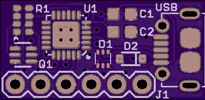
The more I thought about it, the more the solution became obvious: if something doesn't exist, I guess I have to make my own. :) So I did:
![]()
![]()
This is about the simplest CP2102N based programmer circuit I could come up with, reduced to the bare minimum. It has a footprint for a single line header, the idea is that this will be populated with a right angle header so the optional USB programming / UART module can be installed at a 90 degree angle to the main board and require a minimum amount of space on the main board.
The main board will have a footprint like this:
![]()
This is from the Sparkfun Eagle library. The holes are staggered just the right amount that a pin header will lock in place when you just push it in. For a dev board, or in a use case where you actually want the USB port, you just push it in and solder it to make it permanent. In case you just want to program a board and not have the USB in the application, you can push it in, program the board and pull it out again. You can of course also install a female header if you want, but this is supposed to make that unnecessary.
So what do you all think? Good solution? It should make everyone asking to not have the programmer on the board happy as well as those who do want the USB to UART for their application.
I have prototype PCBs on order, once I have built them and tested to make sure it all works, I will make the design files available. I will produce these myself if necessary but this is such a basic thing that I hope others will produce clones and this can become some form of ESP32 programmer standard. It's kind of silly that every ESP32 board out there needs to reproduce this stuff...
I wonder: should I make this its own project on Hackaday.io as well? Maybe I should.
-
Prototype of "something similar" :)
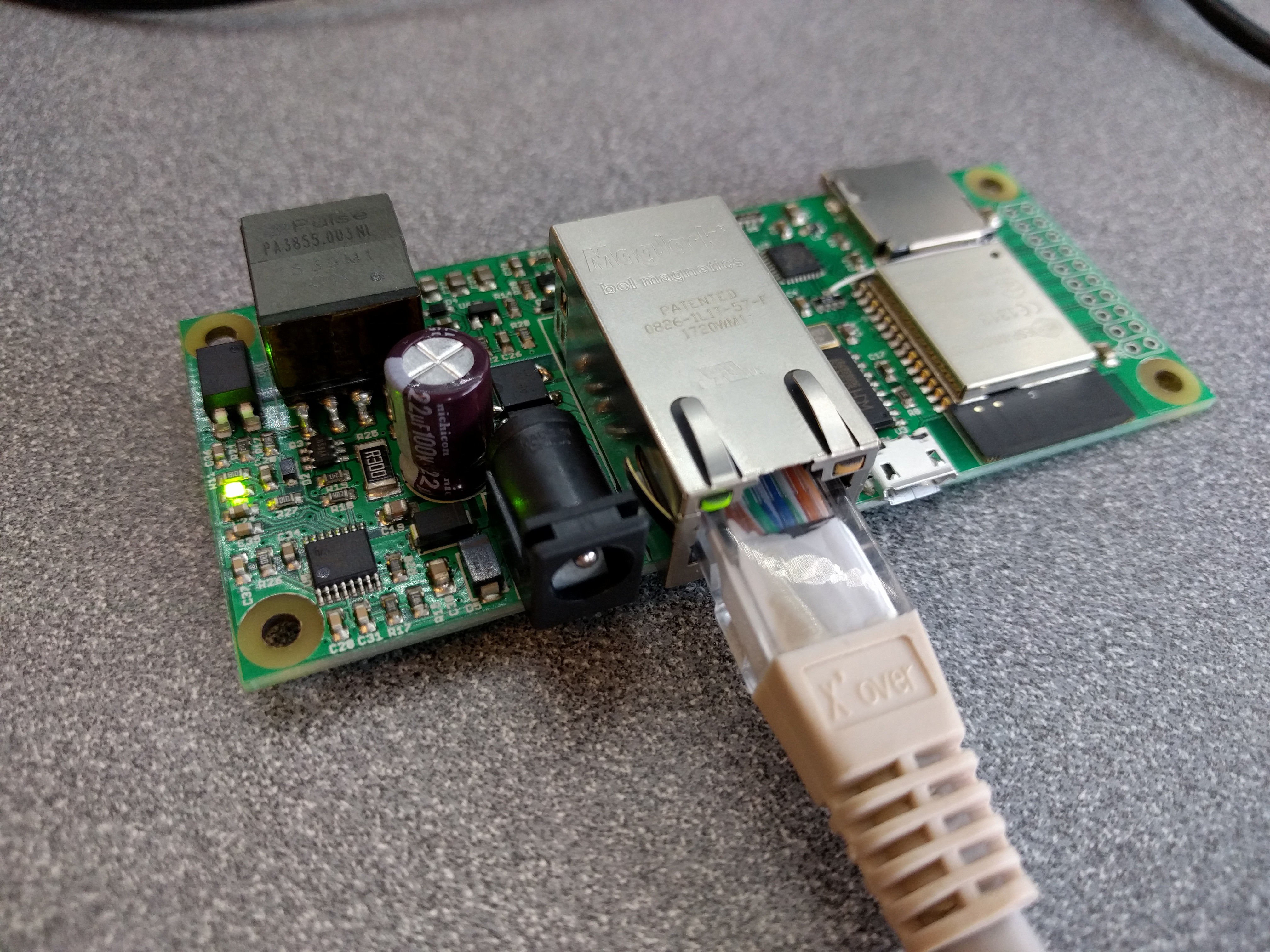
03/31/2018 at 00:01 • 6 commentsI've been referencing this "other similar project" (ESP32 with PoE Ethernet) that I've been working on for a customer. I consider it somewhat of a prototype for what I'm trying to do with the wESP32. Well, I've been working on that and in the interest of showing that it's all very possible, I now have a working prototype of that project:
![]()
At the moment this board has MicroPython on it and can successfully "GET" a web page over Ethernet.
Here's what I want to do different for wESP32:
- Make the isolated power section more compact by using the Si3404, dropping the barrel jack power input and using smaller components where practical. If someone needs to have it in a place where they can't run PoE, a local 802.3af power injector and WiFi can still be used.
- Use a smaller, lower cost Ethernet jack that's still compatible with PoE.
- Replace the CH340G USB programming interface either with a CP2102N or an external "ESP32 programmer".
Several people have told me to make the programming circuitry external. Unfortunately, external "ESP32 programmers" seem to be very rare. There's this one from AnalogLamb but it uses the same CH340G that I'm trying to avoid because it has issues with Macs (it bricked my friend's Macbook). I can't find any other one. Does anyone know of such a thing?
Or does anyone have a strong opinion the other way: they really want built-in USB programming and serial port? One advantage is that it's another way to provide local power if there's no PoE, although the "12V" rail will only be 5V in that case...
Of course, there's also the option to make my own. Just what I need: yet another project. :) - Remove the SD card slot. It shares GPIOs with the GPIO header, so if someone needs it, I figure they can add it to their own custom circuitry.
Thoughts and comments welcome! Project "likes" are very welcome too, since they translate to seed funding at this point. :)
-
Things learned up till now
03/19/2018 at 17:53 • 2 commentsI've mostly been doing component research and gathering user input for now, instead of jumping in and starting detailed design. I've definitely learned a lot doing that and a direction is starting to take shape. Here are some of the things I've learned and conclusions I've drawn:
- There is "proper" standard 802.3af / 802.3at PoE and there is so called "passive" 24V non-standard PoE. Proper standard PoE uses a nominal 48V voltage, accepting 37V-57V. While it would be nice to support everything, including passive 24V PoE, supporting such a wide input voltage range would definitely complicate things.
Consider just the input power. To support the 802.3af PoE Class 3 (12.95W), at the minimum input voltage of 37V, the components need to deal with a current of 0.35A. When trying to support passive 24V PoE as well, components need to deal with 0.54A to allow the same output power. More actually to account for higher cable losses. At the same time everything needs to be rated for 100V as well to ensure reliability, driving up component cost.
Also, the flyback transformers used have a certain winding ratios that works to produce close to the desired output voltages based on expected PoE input voltages, in the duty cycle ranges PoE PWM controllers are designed for. Having to support a wide input range from 24V to 57V again complicates things in having to ensure the PWM controller works reliably and is stable across a wide range of PWM duty cycles.
Moreover, many PoE PD controllers have undervoltage protection that needs to be bypassed to even work at 24V (if possible at all). There are also very good reasons the 802.3af standards people chose such a high 48V voltage: to keep currents low and reduce losses over long, thin gauge Cat 5 cable runs.
All in all, "passive" 24V PoE seems to be just an ugly hack. Yes, you can cheapen things just a bit more when only doing passive, but when trying to support both it definitely complicates things. Yes, you can get passive injectors cheaply on Amazon for $8, but you can also get proper 802.3af injectors for $12. For that small a difference, I really don't see it as a burden to the user to only support standard 802.3af PoE, which is what I intend to do. - If a PoE design has no touchable metal parts or is not connected to anything locally powered, it is acceptable to make the power supply non-isolated. This would make the power supply a little simpler, more compact and lower cost. However, since I can't guess how anyone might use a base board like this, and I intend to have a local programming port that can be connected to a computer, it seems unwise to do this. So I have decided to avoid any issues and make the power supply fully isolated.
- I had expected to be able to save cost by doing a low power (3W or 7W, Class 1 or 2) instead of a "medium power" (Class 3) design, but it turns out to not make much of a difference in cost. It looks like one flyback transformer capable of supporting Class 3 just fine (PA2467NL) is actually the lowest cost option at various distributors. In the volumes I'm looking for (hundreds), it's cheaper than even the 3W flybacks. Must be a matter of volume.
Various people have suggested I do 2 versions: a low cost low power one, and a higher power full featured one. But it looks like power may not turn out to make much difference in cost. It would make a difference in size though, so I may in the future entertain a low power version for that reason. For now, I'll focus on a more generically useful "medium power" version.
I say "medium power" because with the 802.3at and 802.3bt standards it is possible to get much higher power out of PoE. But if working on the #LiFePO4wered/Pi+ has taught me anything, it is that supporting high output power is not trivial and you run into all kinds of unexpected issues. For now "medium power" Class 3 12.95W power seems like a nice target. For most users this will be much more than they ever need, but since it's not going to add cost it seems to be the way to go. And in addition to sensor applications, it will allow "actuator" applications as well (LED lights, motors, solenoids, speakers, ...)--the applications typically causing issues with wireless and requiring wired power. - At first I was bummed to find that the low cost PA2467NL flyback mentioned above is a model designed for 12V output. Since the ESP32 requires 3.3V, I had been looking at making a single voltage design to reduce cost, by removing the need for another regulator. However, as I thought more about the use cases, I became convinced that having both 12V and 3.3V available was actually an excellent option.
If you consider what you can do with 12.95W of power, it is very unlikely you want to use it at 3.3V. Consuming 12.95W at 3.3V would take 3.92A current, requiring fat PCB traces, 2oz copper, and leading to high losses and heat production. Consuming the same power at 12V requires only 1.08A. That's why it's so common to find 12V LED strips, motors, solenoids, sound subsystems etc. Having both 12V and 3.3V available is perfect as far as I'm concerned. - While working on the custom PoE design I just finished, I had found that most common Ethernet jacks don't support PoE because they don't provide access to the data pair's center taps or the extra UTP pairs. You need special jacks that are made to support PoE, so I ended up using a fairly expensive jack in that design.
Now in my search for a low cost alternative, I came across some interesting Chinese options that not only integrate magnetics and high voltage termination / protection caps and resistors, but also the diode bridges required for PoE, all integrated in nice compact jacks. This will save a good amount of space on the PCB. The jack I'm likely going to use is the HanRun HR861153C. - In my search for a PoE PD/PWM chip, the Silicon Labs Si340x family jumped out due to their low cost and high integration (bridge rectifiers, TVS diode, power MOSFET). At first I was focusing on the Si3402-B because of the integrated diode bridges, but when I found a source for the Ethernet jack with diode bridges built-in I shifted my attention to the Si3404-A because it is lower cost, still has the required TVS and supports higher efficiency in the power system by using the auxiliary winding on the flyback transformer.
- I was intending to use the low-cost CH340G USB UART bridge for the ESP32 programming interface, since it's cheap and has worked well for me. But it was brought to my attention that this chip has suffered from continuous driver issues on Apple Macs. So I might change over to a Silicon Labs CP2102N instead. It is significantly more expensive than the CH340G, but it also results in a more compact solution saving PCB space, and it seems wise from a customer support standpoint to not design in a part that causes support headaches. I trust no one has seen driver issues with the CP2102N chip?
- There is "proper" standard 802.3af / 802.3at PoE and there is so called "passive" 24V non-standard PoE. Proper standard PoE uses a nominal 48V voltage, accepting 37V-57V. While it would be nice to support everything, including passive 24V PoE, supporting such a wide input voltage range would definitely complicate things.
-
Initial questions on design trade-offs
03/12/2018 at 19:01 • 10 commentsBased on my current experience with PoE, the following are some concerns I need to tackle in order to create a good but low cost PoE system. I would love to get input from experts in the field and potential users as to what they would like to see!
Cost factors
In my recent customer-specific design, the most costly components from high to low were:
- ESP-WROOM-32 module. I'm sure I could get the cost down if I went from module to bare chip on board, but at this point, I really don't want to deal with the intentional radiator concerns involved in case I end up selling this, so I'm sticking with a module.
- The MagJack Ethernet connector. I was surprised how expensive this was. To be compatible with PoE, you can't just use any random connector, it needs to have specific signals routed out which are usually omitted in low cost Ethernet jacks. Another possibility is to have separate connector and magnetics, but this tends to take more space and I'm not sure at this point if it would save any money. More research is needed.
- Flyback transformer. Ethernet provides magnetic coupling of signals to ensure galvanic isolation, which is needed when connecting devices across long distances. To preserve galvanic isolation of the complete system, the power system requires galvanic isolation as well. This increases cost compared to a non-isolated system. I have read that if a system has no user-touchable metal parts and doesn't connect to anything locally, isolation can be omitted. This would be fine for simple sensor nodes for instance. But I'm reluctant to do this for a generic development board that will be used in who knows which way. I would love to get feedback on this though.
- PoE-PD controller. A specific chip to correctly interface with the 802.3af source equipment. Since PoE uses a nominal voltage of 48V (up to 57V), these chips and the surrounding components should be rated to handle up to 100V, so they tend to be spendy. Unavoidable, but choosing a good part that integrates a lot of the surrounding devices like diode bridges and TVS plus integrates the PWM power controller can reduce the overall system cost and size.
- Ethernet Phy. The ESP32 integrates the Ethernet MAC but an external Phy is required. Unfortunately there is some fun interference going on between pin uses because GPIO0 is used both for boot selection and during programming, and as clock input for the MAC. I'm using the Olimex ESP32 Gateway as a reference for how to deal with this.
Questions to be answered
I need to figure out the following and would love to get input from the community (yes that's YOU :)):
- Which is more important: low cost or isolation? I'll try to reduce cost either way, but an isolated supply is going to cost more and be larger than non-isolated.
- Anyone know a good source for low cost flyback transformers? Low cost means < $1.50 in quantities of 100+ in this case.
- Anyone know a good source for low cost Ethernet Magjacks with PoE connections? Low cost means < $2.50 in quantities of 100+ in this case.
- Availability of higher power output will increase cost. How much power is reasonable? I don't think it makes sense to burden most users with extra cost because someone wants a lot of power, but having some idea of what others find reasonable would be nice.
- The board will likely have 5V and 3.3V power available. 12V and 3.3V is another option. Any preference either way?
- I like using the CH340G as USB UART bridge because it works well for me and has an easy leaded package, but it has been brought to my attention that there are driver issues with it on Macs. Can anyone comment on this? How problematic is it? Is there a solution that works on the most recent OS?
- In general, I'd like to hear: If a thing like this existed, what would you use it for? Answering this question will go a long way in helping me answer the rest. :)
- Related to the above: does something like this exist already and have I somehow missed it? Can you point me to it? Thanks. :)
wESP32: Wired ESP32 with Ethernet and PoE
A low cost ESP32 core board with Ethernet and PoE for convenient "single cable" deployments