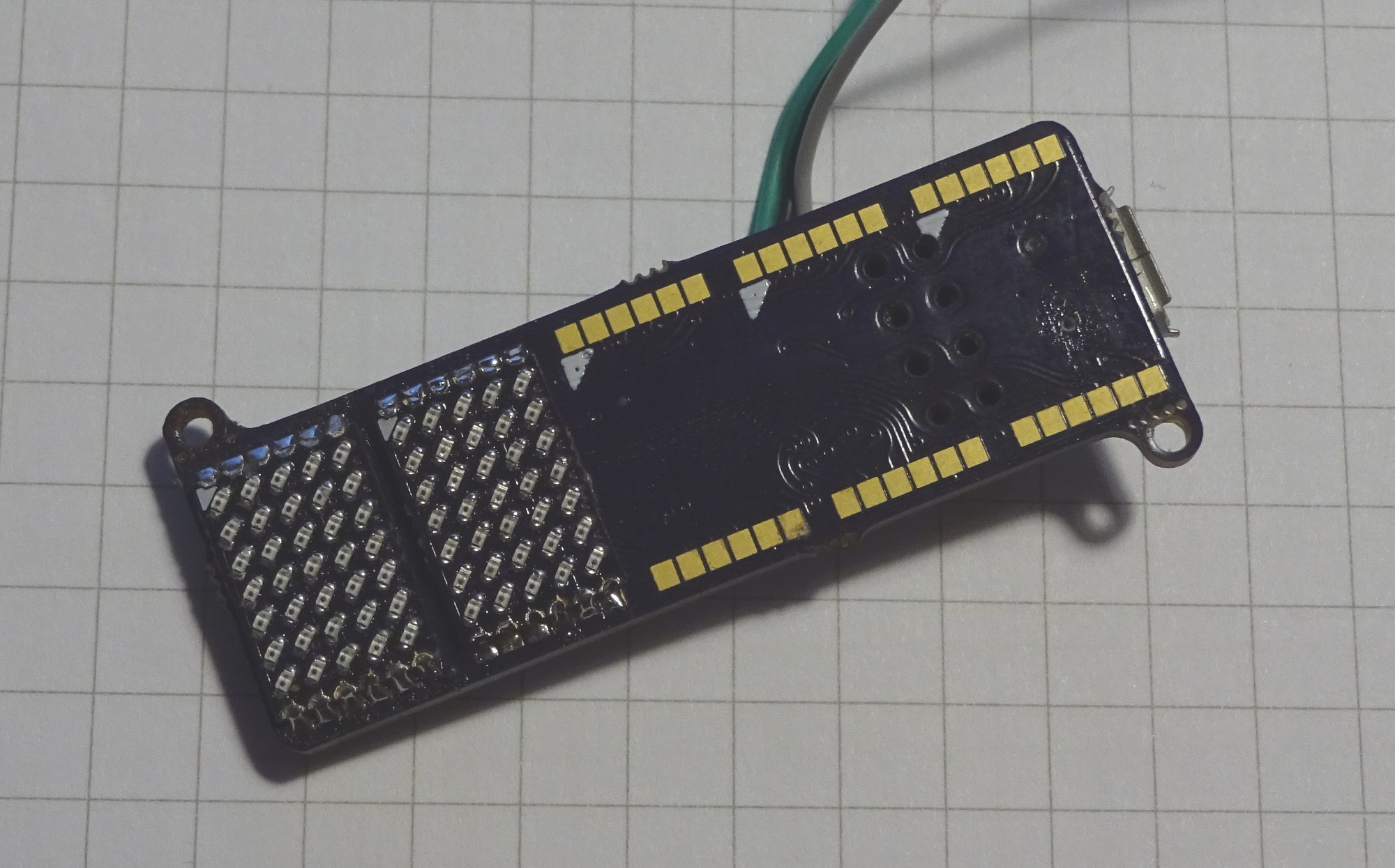
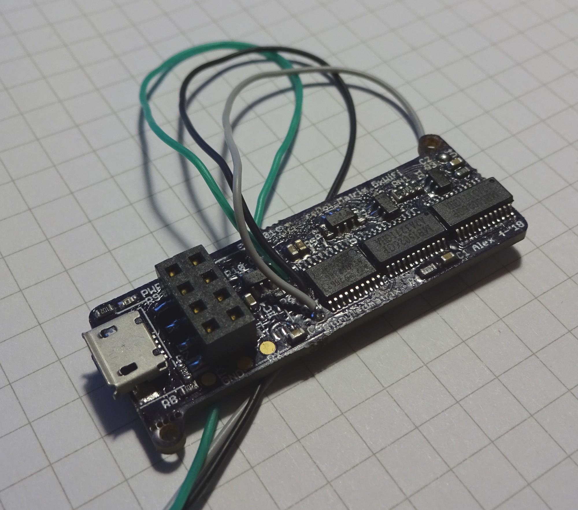
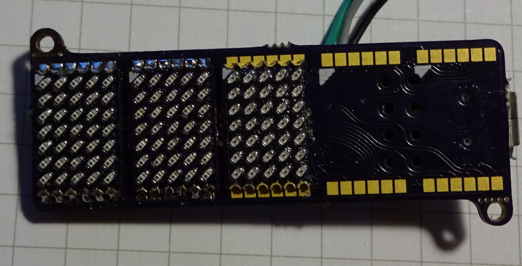
Here are some quick images of the current Hardware state: The Grind in the background is 5mm (~0.2'')

Two matrix-PCBs are soldered. They are also working, but I have no good images so far.

The back with the two LED driver ICs, a STM8s microcontroller, pinheader for ESP-01 and USB-connector for power
Can you spot the mistake on the next image?

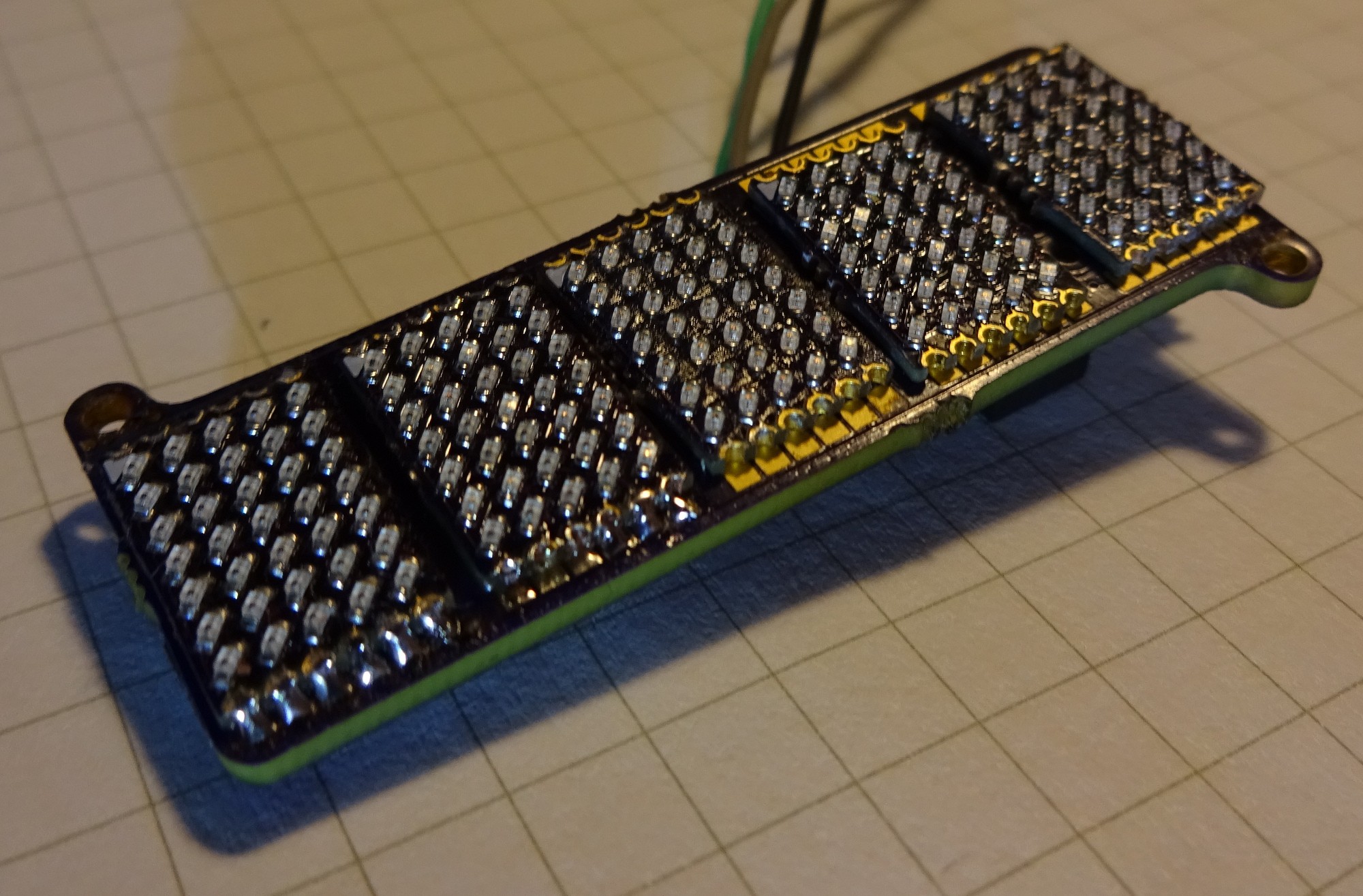
Saw it? The LEDs on the third not soldered Matrix PCB are soldered 180° rotated. This does not work with the main PCB. But sadly the cathode marking on the matrix PCBs is wrong. And I soldered the first five matrix PCBs wrong for the main PCB. With five not usable matrix PCBs I run out of LEDs sadly :(

Like this it should look at the end.
Now I will work on the STM8 firmware. So far only switching all LEDs on is working.
 Alex
Alex
Discussions
Become a Hackaday.io Member
Create an account to leave a comment. Already have an account? Log In.