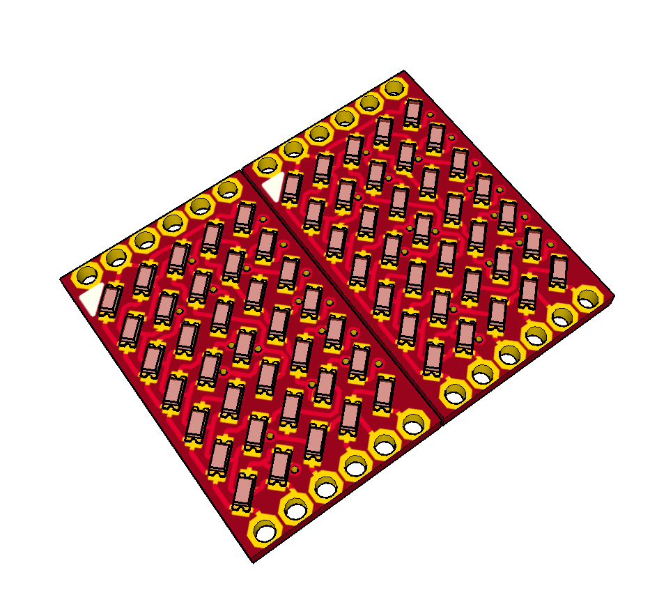
For this project I will use Matrix-PCBs. These Matrix PCBs will get soldered on the main PCB. Main features are:
- 5x7 0402 LED Matrix
- no components on the back
- castellated holes (50mil /1.27mm pitch) on the sides to connect to main PCB
I also orderd some PCBs at OSH-Park to test this. The LED Matrix itself is the same as the latest Version of #reDOT_smart but this project will see no update.
The rendering (made with eagleUp and SketchUp) show two of the Matrix PCBs side be side, as they will get mounted on the Main PCB (castellated holes not shown right) .

Further on I will design the Main PCB but I did not decided many things there. For example one main/important decision would be the microcontroller. My favorites so far would be
- ESP8285 - to get wifi
- Atmega328P - the classic one
- SAMD09/11/21 - modern Arm core, but maybe little bit overkill
- PIC16/18 with USB - it looks like implementing USB on PIC is easier then on SAMD11/21
Do you have any thoughts about this selection or do you have an Idea for an additional microcontroller to consider? Than please leave a comment!
Based on microcontroller Selection I will chose additional components like Shift registers to expand IOs, led driver, clock stuff, power connector, interface connector an so on.
 Alex
Alex
Discussions
Become a Hackaday.io Member
Create an account to leave a comment. Already have an account? Log In.