jaromir.sukuba
-
New devices support
08/16/2016 at 06:42 • 0 commentsAmount of supported devices increased from 68 to 131. Some new PIC16F1xxx were added (16F151x, 16F178x, 16F19xx) and completely new PIC18 family was added - PIC18FxxJxx (like 18F26J50); which also required updated programmer firmware. Not all members of this family are here yet, that is subject of next release.
Everything is on github and updated support table is at the project details section too.
-
New devices support update
08/05/2016 at 06:00 • 0 commentsI increased number of supported devices from 48 to 68 (PIC16F1619 family and PIC16F1579 family added) and tested a few new ones.
Sources at github, as usual.
-
PIC16F USB devices added
07/30/2016 at 20:34 • 1 commentI added support for PIC16F1454, 1455, 1459 and LF variants. I had PIC16F1455 at hand, so I tried to upload some small program and it worked as expected.
Some minor mistakes fixed for PIC12F18xx.
PIC12F1840, PIC16F1503, PIC16F1509 tested and working too.
PIC programmer sketch verified to run on 2USD chinese arduino nano clone with CH340 USB-serial converter.
![]()
-
A lot of new devices supported
07/29/2016 at 12:54 • 1 commentMajor device support update
DEVICE	        TESTED
PIC12F1501
PIC12F1571
PIC12F1572	YES
PIC12F1822
PIC12F1840
PIC12LF1501
PIC12LF1571
PIC12LF1572	YES
PIC12LF1822
PIC12LF1840
PIC16F1503
PIC16F1507	YES
PIC16F1508
PIC16F1509
PIC16F1824
PIC16F1825
PIC16F1826
PIC16F1827
PIC16F1828
PIC16F1829	YES
PIC16F1847
PIC16LF1503
PIC16LF1507
PIC16LF1508
PIC16LF1509
PIC16LF1824
PIC16LF1825
PIC16LF1826
PIC16LF1827
PIC16LF1828
PIC16LF1829	YES
PIC16LF1847
PIC18F25K22
PIC18F25K50	YES
PIC18F26K22
PIC18F45K22
PIC18F46K22
PIC18LF25K22
PIC18LF25K50	YES
PIC18LF26K22
PIC18LF45K22
PIC18LF46K22
From something like dozen of devices we've got 42 devices supported, not all of them are verified though. Many of the devices are very very similar, or are derivative of some verified type, so I'm rather sure it should work. -
PIC12F1xxx support
07/26/2016 at 11:24 • 0 commentsLast time I made quick hack to support PIC18, I introduced a few bugs along the way. I ironed it out and added support for a few new devices, namely PIC12F1571 and 1572, as well as LF version of the same. Similar PIC devices should be easy to add. I have to add changes that @webwicht made in previous log.
Sources are on github, as usual. Old sources were removed, now ouy have pp3.c (compile as per instructions in this howto) and pp.ino (arduino sketch) as the only two sources you need.
-
Modifications for Windows Version (MINGW)
06/13/2016 at 19:31 • 2 commentsFor using the programmer (pp3.c) under Windows some minor changes:
1. Uncomment (or better replace) delay functions in sleet_ms()
2. Retrying ReadFile() if 0 bytes are read:
int getByte()
{
	int ntotal=0;
	unsigned char buf[2];
	int n;
	do
	{
		ReadFile(port_handle, buf, 1, (LPDWORD)((void *)&n), NULL);
		ntotal++;
	} while(n==0 && ntotal<50);
	if (verbose>3)
		flsprintf(stdout,n<1?"RX: fail\n":"RX:  0x%02X\n", buf[0] & 0xFF);
	if (n == 1)
		return buf[0] & 0xFF;
	comErr("Serial port failed to receive a byte, read returned %d\n", n);
	return -1; // never reached
}
3. Changes in InitSerialPort():#if defined(__linux__) strcpy(portname,"\\\\.\\"); #else strcpy(portname,""); #endifCompiling with: gcc pp3.c -o pp3.exe
And here changes for PIC18f4622 CPU:
else if (strcmp("18f46k22",cpu)==0) { flash_size = 32768; page_size = 64; devid_expected = 0x5400; devid_mask = 0xFFE0; chip_family = CF_P18F_A; } -
Goals slightly revisited, PIC18F25K50 support
04/01/2016 at 22:40 • 2 commentsI stated in my first log that this one will be only PIC16F1xxx programmer and nothing else. Well and now it isn't true. I added support for PIC18F25K50 and friends, see on github. Believe or not, this MCU is used in #Badge for Hackaday | Belgrade Conference, what a coincidence.
For now the sources are just quick hack of my PIC16F1xxx programmer (which was quick hack on itself) with added functions for PIC18F devices. Oh yes and now the programmer crunches hex files directly, no need to convert it into bin files anymore!
Blink a LED HOWTO, Linux
First, we need to prepare something to be flashed into PIC, then connect hardware and finally flash the binary..
Step one, SDCC
Download and build gputils
$ svn co https://gputils.svn.sourceforge.net/svnroot/gputils/trunk/gputils gputils_svn
$ cd gputils_svn/
$ ./configure
$ sudo make install
Download latest snapshot SDCC and install it: Extract the binary kit to a temporary directory, let's name it sdcc-temporary. Jump here and copy all files to /usr/local, perhaps with root access
# cd sdcc-temporary
# cp -r * /usr/local
Then test both of the components:
# gpasm -v
gpasm-1.4.0 #1107 (Nov 11 2015)
#sdcc -v
SDCC : mcs51/z80/z180/r2k/r3ka/gbz80/tlcs90/ds390/pic16/pic14/TININative/ds400/hc08/s08/stm8 3.5.5 #9380 (Linux)
published under GNU General Public License (GPL)
So far so good.Step two, build target binary
Take this source
#include "pic18f25k50.h"		//inculde MCU specific headers

#pragma config XINST=OFF		//good old instruction set, don't change this
#pragma config WDTEN = OFF		//we don't need WDT here
#pragma config FOSC = INTOSCIO		//internal oscillator, IO on RA6,7

volatile int i,j;			//declare them volatile, we don't want the compiler to optimize out the delay

void main(void)
{
    OSCCON = 0x70;			//switch the internal oscillator to 16MHz
    ANSELC = 0;				//make all C IO digital
    TRISC = 0x00;			//and make them IO outputs
    while (1)
    {
        LATC = ~ LATC;			//flip all C pins to opposite state
        for (i=0;i<20000;i++) j++;	//and burn some time
    }

}
name it sdcc_blink.c and enter# sdcc --use-non-free -mpic16 -p18f25k50 sdcc_blink.c
this should result into a few generated files, but we are interested in hex file, in my case looking like:020000040000FA :1000000002EF00F017EEFFF027EEFFF0F86AA68E81 :10001000A69CE9680E0EEA6E0068ED6A0050FDE1EC :10002000EE0EF66E000EF76E000EF86E0900F5CFBC :1000300005F00900F5CF06F034D00900F5CF00F047 :100040000900F5CF01F00900F5CF02F00900090021 :10005000F5CFE9FF0900F5CFEAFF09000900090023 :10006000F5CF03F00900F5CF04F009000900F6CF41 :1000700007F0F7CF08F0F8CF09F000C0F6FF01C095 :10008000F7FF02C0F8FF03D00900F5CFEEFF03062B :10009000FBE20406F9E207C0F6FF08C0F7FF09C05B :1000A000F8FF0506CAE20606C8E258EC00F0FFD7E2 :1000B000700ED36E946A0F015D6B8B1E0001606B36 :1000C0000001616B00016151800F320F03E1200ECE :1000D0000001605DF2E20001623F02D00001632B8B :1000E0000001603F02D00001612BECD7120001003B :0E00F000FC00000064000000010000000000A1 :020000040030CA :0100010028D6 :010003003CC0 :010006008574 :00000001FF
Now we need to setup the programmer itselfProgrammer
Take source of pp3.c and build it
# gcc pp3.c -o pp3
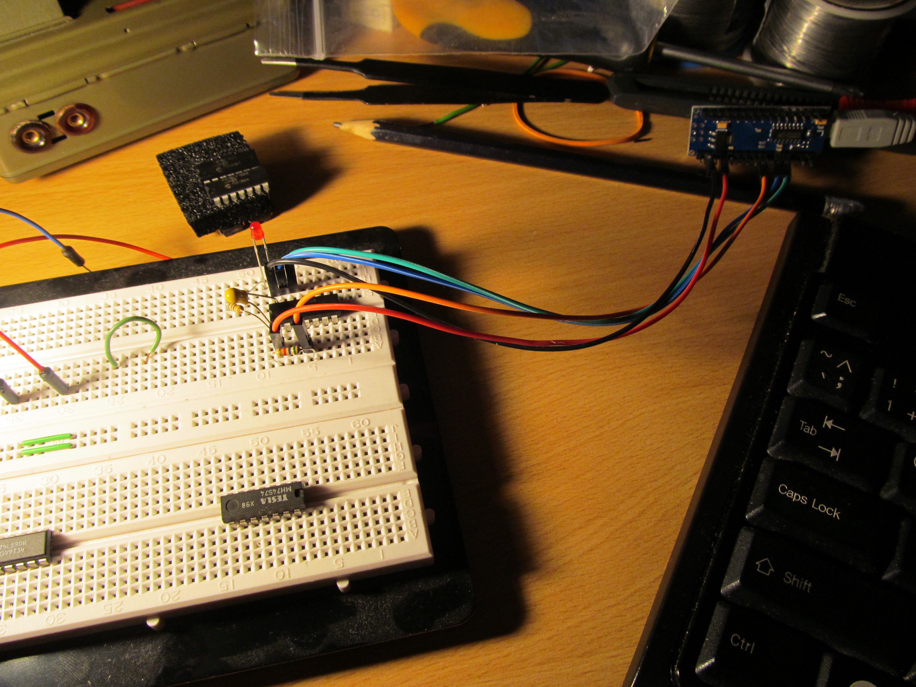
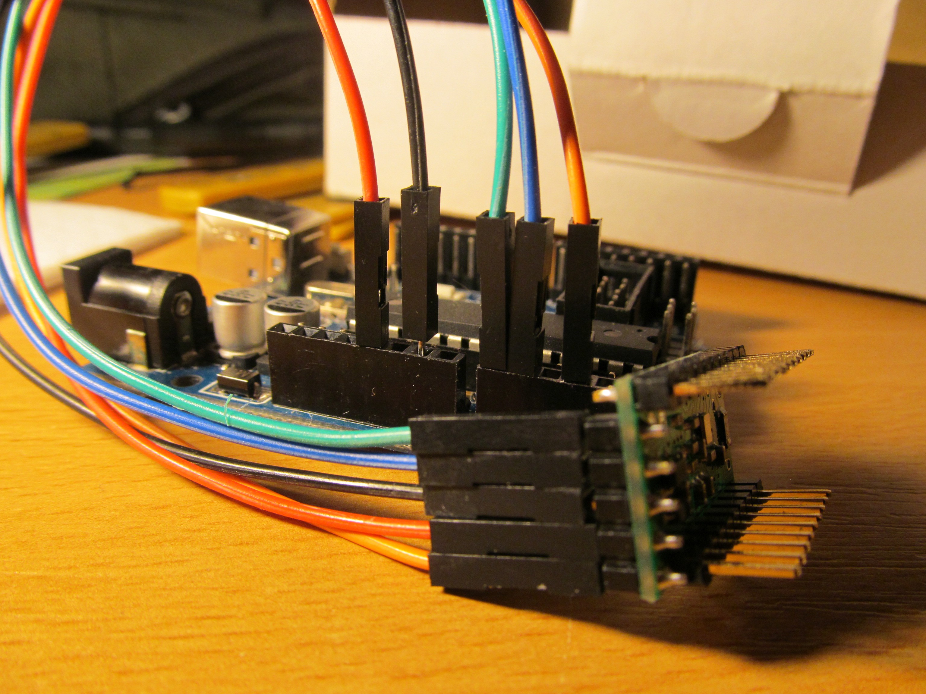
This should run quietly and produce executable pp3. With no parameters it should print banner and finish.Take arduino and connect A3 to MCLR, A1 as PGD (RB7), A0 as PGC (RB6) of target PIC, plus ground and power from Arduino, for example. I used pololu p-star board with PIC18F25K50
![]()
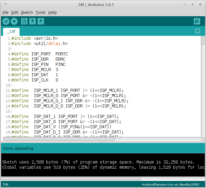
Flash programmer sketch into your arduino.
![]()
Now you should be ready to flash the PIC
FLASH, Gordon!
Run command
# ./pp3 -c /dev/ttyUSB0 -s 2000 -t 18f25k50 sdcc_blink.hex
and you should get something like
Opening serial port
Sleeping for 2000 ms while arduino bootloader expires
pp
Device ID: 5c20
Programming FLASH (32768 B in 512 pages per 64 bytes):
4 pages programmed
Programming config
Verifying FLASH (32768 B in 512 pages per 64 bytes):
4 pages verified
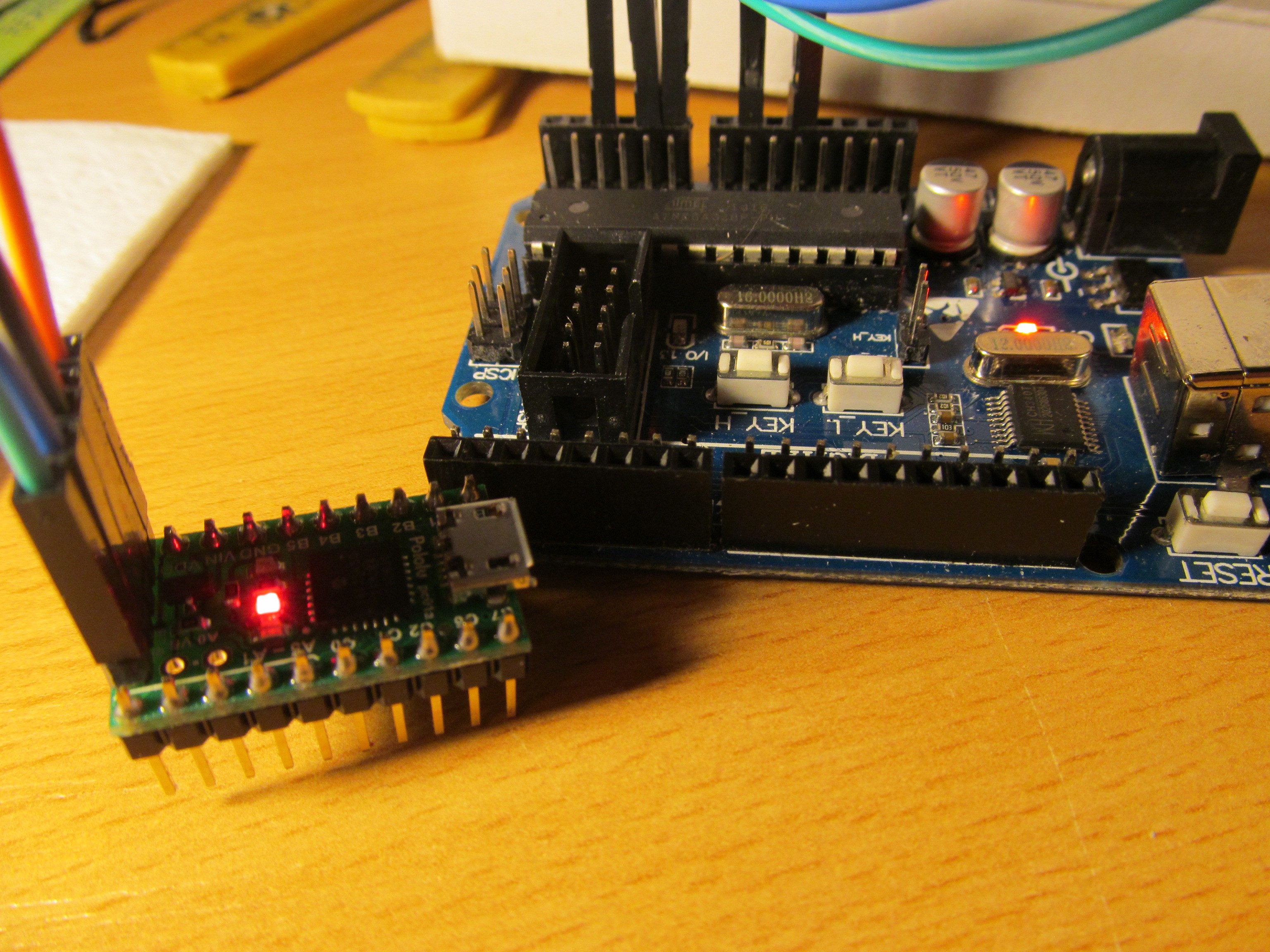
...and LED should blink.
Rinse and repeat![]()
Now you can make changes in the sdcc_blink.c source and run those two commands to build and reflash the firmware
# sdcc --use-non-free -mpic16 -p18f25k50 sdcc_blink.c
# ./pp3 -c /dev/ttyUSB0 -s 2000 -t 18f25k50 sdcc_blink.hex
Enjoy. -
Modifying the sources for new devices
01/18/2016 at 09:37 • 5 commentsCurrently, the supported devices are 16F1507, 16F1508, 16F1509, 16F1825 and 16F1829 with LF variants for the latter two.
Though I'm planning to add more devices, you may want to try it by yourself. For basic PIC16F1xxx devices, you have to add new lines into setCPUtype function in pp2.c file. Each MCU has its descriptor, looking like
if (strcmp("16f1507",cpu)==0)
{
flash_size = 4096; //bytes, where 1word = 2bytes, though actually being 14 bits
page_size = 32; //bytes
devid_expected = 0x2D00;
devid_mask = 0xFFE0;
}
It is determined by four parameters:
flash size - its size is in words, where one word is calculated as two bytes, though the single program word occupies only 14 bits.
page size - this is the biggest chunk of FLASH that can be written at once.
devid_expected - clean device ID, where revision is chopped off
devid_mask - mask to be AND-ed with word from address 8006h to get clean device ID.
Say you want to add PIC16F1503. Download the datasheet and if you are lazy, search for "Device ID" string. One of the first search results should get you to the chapter 4.6, named Device ID and Revision ID
You can see what revision looks like, so lets create mask to chop off, where revison bits are![]()
0010 1101 111x xxxx - ID register, where x are revision bits
1111 1111 1110 0000 - MASK to leave ID untouched
F    F    E    0    - MASK in hex format
0010 1101 1110 0000 - ID register without revision bits
2    D    E    0    - ID in hex format
The device ID translates to 2DE0 hexadecimal and mask to FFE0 hexadecimal. Now we have to determine FLASH size and page size.
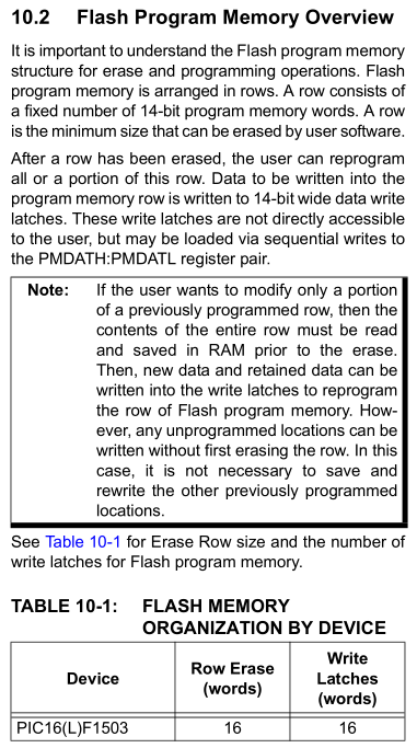
In the same datasheet, go to chapter "Flash program memory control", or search for "latches". You should find chapter 10.2, where is described size of erase and write block.
![]()
The write latches buffer the data to be written into FLASH, so our page size is as big as amount of latches. Because flash is erased in bulk, write latches are interesting - there are 16 words of write latches, making 32 bytes of FLASH write "buffer".
Flash size is easy to determine, on second page of datasheet is comprehensive table
where PIC16F1503 has 2048 words of FLASH, translating into 4096 bytes. So, complete entry for PIC16F1503 should look like this![]()
if (strcmp("16f1503",cpu)==0)
{
flash_size = 4096;
page_size = 32;
devid_expected = 0x2DE0;
devid_mask = 0xFFE0;
}
Recompile, run and enjoy.
-
Arduino programmer forked
01/07/2016 at 14:23 • 0 commentsI ported sources of this Arduino programmer to PIC16F series, allowing to run on cheap K150 programmer. Though it is related to this project, it is probably going to divert from this one, so I started new project here.
-
Programming micro progmeter
12/24/2015 at 22:17 • 0 commentsWell, this is the reason why I started with this project - to give open-sourced programmer to my micro progmeter project.
Here you can see video of both devices in action. At first, wiping out old firmware with display test, then reverting back to original firmware.
Microchip PIC Arduino based programmer
I love to program programmers. Yo dawg...