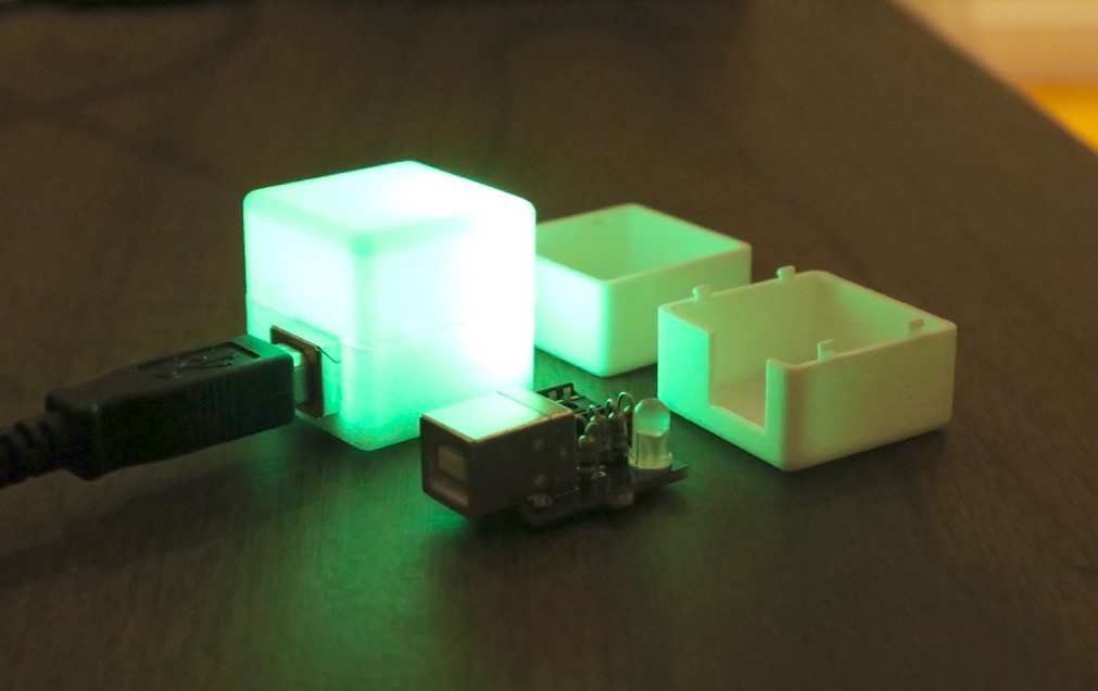
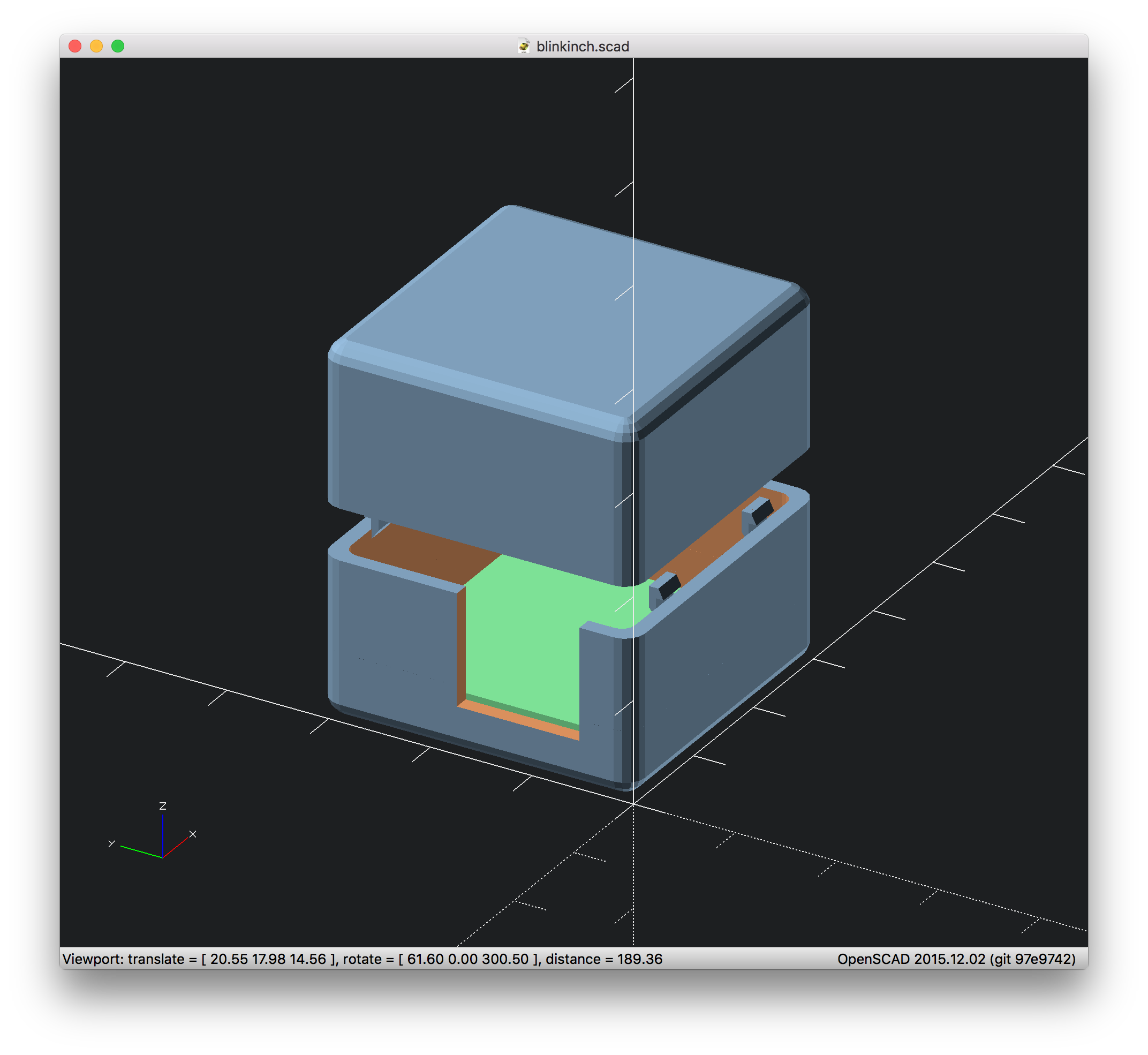
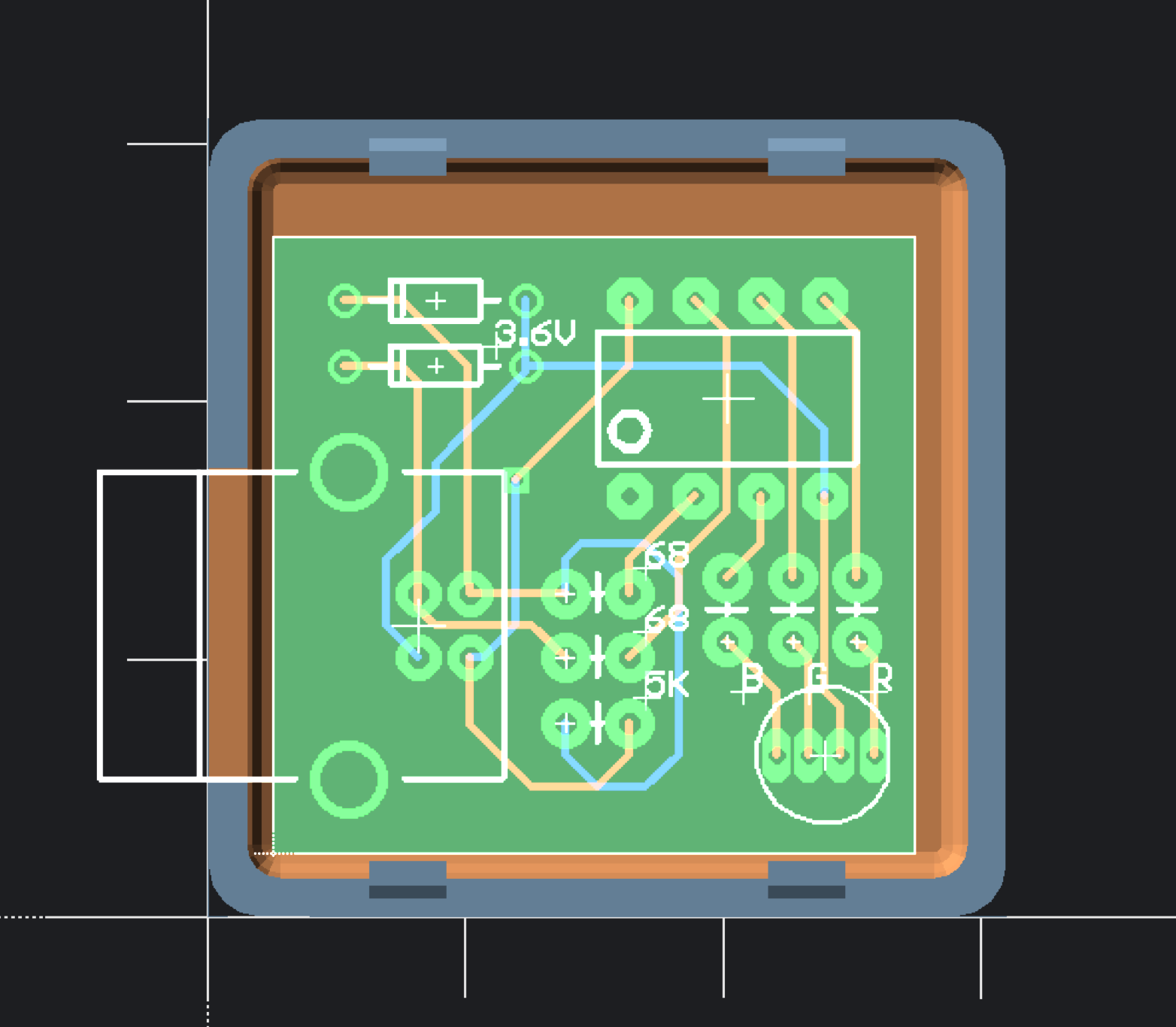
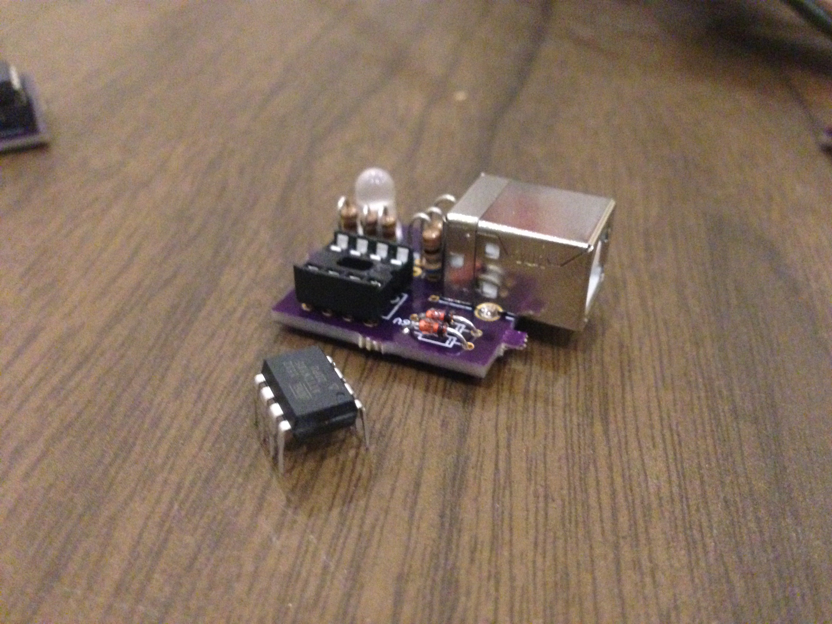
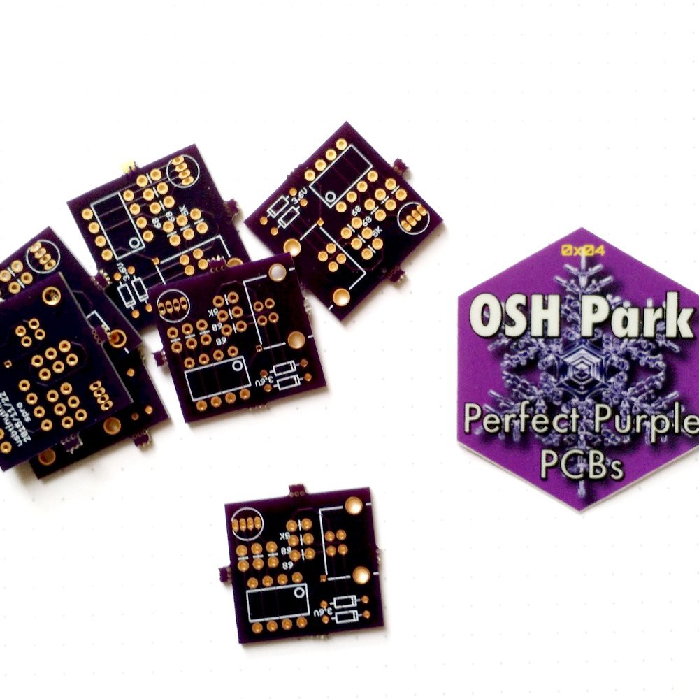
Clone of the blink(1) indicator light with ATTiny85 and V-USB
To make the experience fit your profile, pick a username and tell us what interests you.
We found and based on your interests.
I came back from holiday vacation to discover a Shapeways box waiting on the doorstep. Inside I found two copies of the 3d printed cube enclosure, which came out looking nice, fit together well, and let enough light through to show up in sunlight.
The light is a little unbalanced in the corner but that's more an issue with the LED placement than the cube itself.
Starting with a fork of the ATTinyTemp enclosure i created a rounded cube enclosure for the blink(inch) in OpenSCAD. It is just a bit larger than an inch^3, and thanks to the original parametric design the only real effort went into making sure the hole for the USB plug was the right size.
To test the circuit I used the HID mouse wiggling example from http://codeandlife.com/2012/02/11/v-usb-tutorial-continued-hid-mouse/ . I've had troubles with enumeration before with V-USB and ATTiny85 but having the 3.6V zener diodes seems to mitigate that -- it enumerated on the first try.
I also ran a non-USB color fading test with pleasant results
The design files are now in this repo: https://github.com/spro/blinkinch. It includes the Eagle schematic and board files plus a .zip of gerber and drill files
While I wait for the PCBs to arrive from OSHPark I'll use an equivalent breadboard to start developing the firmware and driver.
My current conception of the driver exposes a service with a single method:
setRGB(r, g, b, message=null)
Scripts can go about their business (e.g. poll the bitcoin price) and call the service when they want to display some information (e.g. setRGB(255, 0, 0) when the price is declining). The optional message parameter can be used to explain the change, potentially showing up as an unobtrusive notification (like Growl).
Create an account to leave a comment. Already have an account? Log In.
This is your one-week reminder to upload design documents: https://hackaday.io/project/7813-the-square-inch-project/log/28566-design-deadline
Hey, just for your information—your PCB can be smaller and have a different size than a 1x1 inch square. However, it must fit within that square—a 0.5x2 inch rectangle wouldn't be allowed.
1"x1" is probably more than enough space for this but my soldering fingers aren't very nimble :)
Become a member to follow this project and never miss any updates
[verified: no design files missing]