 Lentin Joseph
-
1Step 1
As the title says, we are going to see how to build an autonomous mobile robot called Chefbot which is for serving food and beverages in hotels and restaurants.
This was a hobby project and i built this robot after seeing a robot calledTurtlebot2. The main aim of the project was to build an open source autonomous mobile robot research platform and doing some application using it. Serving food was one of the application of the robot and i have named the robot as Chefbot.
Note : The robot is not using Roomba as the base platform which is used in Turtlebot2; instead of Roomba, i have built the entire mechanism from scratch.
I have documented the entire building procedure of this robot into a book calledLearning Robotics using Python published by PACKT publishers. The book already featured in R.O.S Blog, Robohub, OpenCV website, Python book listetc.
The header images shows the book cover page and the Chefbot prototype.
This tutorials is a quick start guide for developing this robot, for detailed designing and development, you should refer the book itself.
You should have basic knowledge in Python and ROS for starting with this tutorials.
In this tutorials series, you can see an abstract of each chapters of this book. Following are main steps that we are going to discuss
- Mechanical Design of Chefbot
- Working with Robot Simulation using ROS and Gazebo
- Designing Chefbot Hardware
- Interfacing Robotics Actuators and Wheel Encoders
- Working with Chefbot Sensors
- Programming Vision sensors using R.O.S and Python
- Working with Speech Recognition and Synthesis
- Applying Artificial Intelligence to Chefbot using Python
- Integrating of Chefbot Hardware and Interfacing to ROS using Python
- Designing a GUI for Chefbot using Qt and Python
- Calibrating and Testing of Chefbot
-
2Step 2
Step 1: Mechanical Design of Chefbot
![]()
![]()
![]()
![]()
![]()
![]()
![]()
In this step, we can see an abstract of the Chefbot design process mentioned in the book.
The robot design starts from a set of requirements.
Following conditions have to be met by the robot design.
Here are the requirements- The robot should have a provision to carry food and drinks.
- The robot should be able to carry a maximum payload of 5 kg.
- The robot should travel at a speed between 0.25 m/s and 1 m/s
- The ground clearance of the robot should be greater than 3 cm
- The robot must be able to work for 2 hours continuously
- The robot should be able to move and supply food to any table by avoiding obstacles
- The robot height should be between 40 cm and 1 meter
- The robot should be of low cost
After analyzing and designing from the requirement we are coming to the conclusion that, following parameters should be on the robot.
Motor Specification- Robot drive : Differential wheeled drive
- Required Motor Speed : 80 RPM
- Wheel diameter : 9 cm
- Motor Torque : 20 Kg-cm
So we should design a drive system of robot and buy motors that is matching with these specs.
Next step is to design the robot chassis.
Robot Chassis DesignWe are taking the 3-platform layered architecture in this robot which is similar to Turtlebot 2.
I have used following free software tools for sketching and viewing the 2D and 3D design of the robot
- LibreCAD: LibreCAD is a fully comprehensive 2D CAD application that you can download and install for free.
- Blender: Blender is the free and open source 3D modeling tool.
- Meshlab : MeshLab is an open source, portable, and extensible system for the processing and editing of unstructured 3D triangular meshes.
In Ubuntu you can install these tool using following command
Installing LibreCAD
$ sudo apt-get install librecad
Installing Blender
$ sudo apt-get install blender
Installing Meshlab
$ sudo apt-get install meshlab
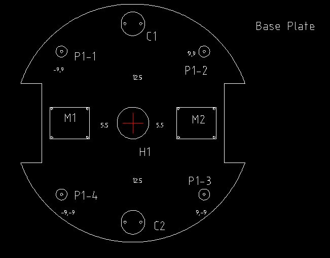
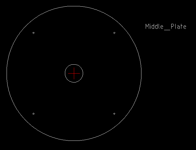
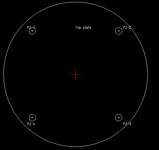
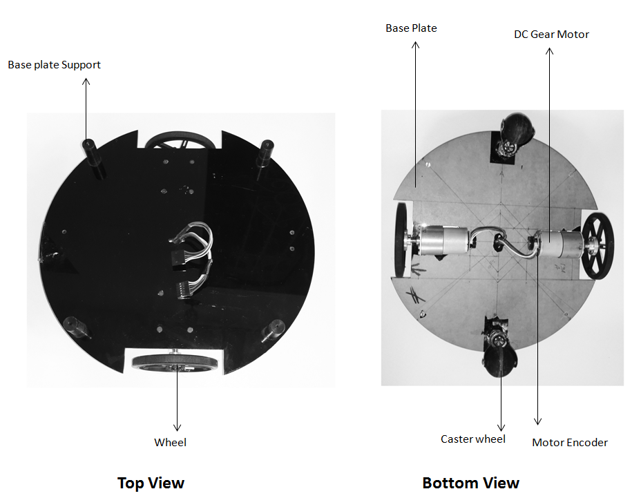
You can see the 2D design of robot, base plate, middle plate and top plate of the robot modeled using LibreCAD.
The dimensions of plates and dimensions of each holes are given below
DimensionsHere are the dimensions of each plate
Base plate:
- M1 and M2(motors): 5x4 cm
- C1 and C2(caster wheels) Radius : 1.5 cm
- S(Screw) radius : 0.15 cm
- P1-1,P1-2,P1-3,P1-4 : Outer radius = 0.7 cm, Height = 3.5 cm
- Left and Right Wheel sections : 2.5 x 10 cm
- Base plate Radius: 15 cm
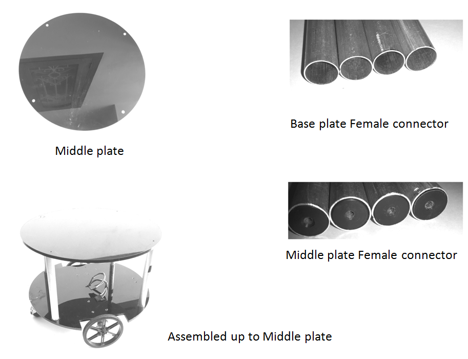
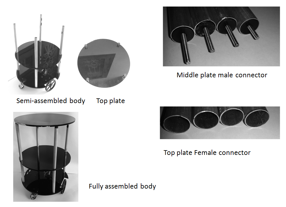
The middle and top plate have the same dimensions of base plate with same screw size and other dimensions. You can view these plates from the image gallery.
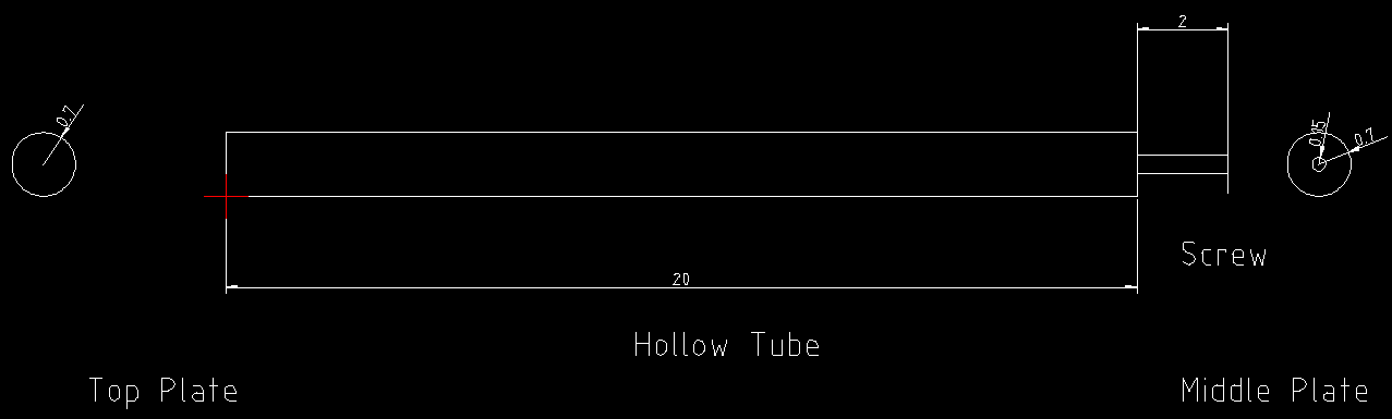
Each plates are connected using hollow tubes with screws. You can see its dimensions from the images.
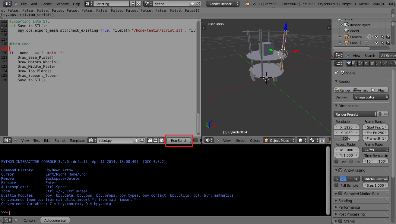
The 3D modeling is done using Python script inside Blender. You can see screenshot of Blender with robot model from the images.
The Python script and Blender 3D model file is attached along with this step.
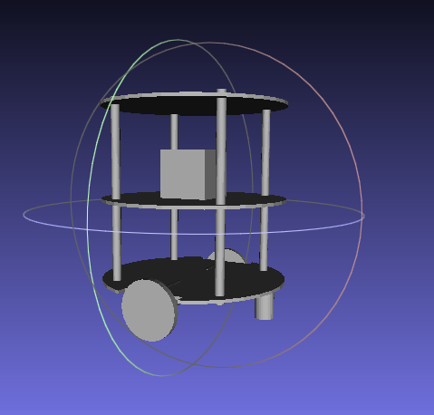
We can export the robot model to STL it can viewed in 3D mesh viewing tool called Meshlab which is included in the images.
The python script to generate robot model in Blender is given below
import bpy #This function will draw base plate def Draw_Base_Plate(): #Added two cubes for cutting sides of base plate bpy.ops.mesh.primitive_cube_add(radius=0.05, location=(0.175,0,0.09)) bpy.ops.mesh.primitive_cube_add(radius=0.05, location=(-0.175,0,0.09)) ################################################ #Adding base plate bpy.ops.mesh.primitive_cylinder_add(radius=0.15,depth=0.005, location=(0,0,0.09)) #Adding booleab difference modifier from first cube bpy.ops.object.modifier_add(type='BOOLEAN') bpy.context.object.modifiers["Boolean"].operation = 'DIFFERENCE' bpy.context.object.modifiers["Boolean"].object = bpy.data.objects["Cube"] bpy.ops.object.modifier_apply(modifier="Boolean") ################################################ #Adding booleab difference modifier from second cube bpy.ops.object.modifier_add(type='BOOLEAN') bpy.context.object.modifiers["Boolean"].operation = 'DIFFERENCE' bpy.context.object.modifiers["Boolean"].object = bpy.data.objects["Cube.001"] bpy.ops.object.modifier_apply(modifier="Boolean") ################################################ #Deselect cylinder and delete cubes bpy.ops.object.select_pattern(pattern="Cube") bpy.ops.object.select_pattern(pattern="Cube.001") bpy.data.objects['Cylinder'].select = False bpy.ops.object.delete(use_global=False) #This function will draw motors and wheels def Draw_Motors_Wheels(): #Create first Wheel bpy.ops.mesh.primitive_cylinder_add(radius=0.045,depth=0.01, location=(0,0,0.07)) #Rotate bpy.context.object.rotation_euler[1] = 1.5708 #Transalation bpy.context.object.location[0] = 0.135 #Create second wheel bpy.ops.mesh.primitive_cylinder_add(radius=0.045,depth=0.01, location=(0,0,0.07)) #Rotate bpy.context.object.rotation_euler[1] = 1.5708 #Transalation bpy.context.object.location[0] = -0.135 #Adding motors bpy.ops.mesh.primitive_cylinder_add(radius=0.018,depth=0.06, location=(0.075,0,0.075)) bpy.context.object.rotation_euler[1] = 1.5708 bpy.ops.mesh.primitive_cylinder_add(radius=0.018,depth=0.06, location=(-0.075,0,0.075)) bpy.context.object.rotation_euler[1] = 1.5708 #Adding motor shaft bpy.ops.mesh.primitive_cylinder_add(radius=0.006,depth=0.04, location=(0.12,0,0.075)) bpy.context.object.rotation_euler[1] = 1.5708 bpy.ops.mesh.primitive_cylinder_add(radius=0.006,depth=0.04, location=(-0.12,0,0.075)) bpy.context.object.rotation_euler[1] = 1.5708 ################################################ #Addubg Caster Wheel bpy.ops.mesh.primitive_cylinder_add(radius=0.015,depth=0.05, location=(0,0.125,0.065)) bpy.ops.mesh.primitive_cylinder_add(radius=0.015,depth=0.05, location=(0,-0.125,0.065)) #Adding Kinect bpy.ops.mesh.primitive_cube_add(radius=0.04, location=(0,0,0.26)) #Draw middle plate def Draw_Middle_Plate(): bpy.ops.mesh.primitive_cylinder_add(radius=0.15,depth=0.005, location=(0,0,0.22)) #Adding top plate def Draw_Top_Plate(): bpy.ops.mesh.primitive_cylinder_add(radius=0.15,depth=0.005, location=(0,0,0.37)) #Adding support tubes def Draw_Support_Tubes(): #################################################### #Cylinders bpy.ops.mesh.primitive_cylinder_add(radius=0.007,depth=0.30, location=(0.09,0.09,0.23)) bpy.ops.mesh.primitive_cylinder_add(radius=0.007,depth=0.30, location=(-0.09,0.09,0.23)) bpy.ops.mesh.primitive_cylinder_add(radius=0.007,depth=0.30, location=(-0.09,-0.09,0.23)) bpy.ops.mesh.primitive_cylinder_add(radius=0.007,depth=0.30, location=(0.09,-0.09,0.23)) #Exporting into STL def Save_to_STL(): bpy.ops.object.select_all(action='SELECT') # bpy.ops.mesh.select_all(action='TOGGLE') bpy.ops.export_mesh.stl(check_existing=True, filepath="/home/lentin/Desktop/exported.stl", filter_glob="*.stl", ascii=False, use_mesh_modifiers=True, axis_forward='Y', axis_up='Z', global_scale=1.0) #Main code if __name__ == "__main__": Draw_Base_Plate() Draw_Motors_Wheels() Draw_Middle_Plate() Draw_Top_Plate() Draw_Support_Tubes() Save_to_STL() -
3Step 3
Step 2: Working with Robot Simulation using R.O.S and Gazebo
![]()
![]()
![]()
![]()
After designing the robot 3D model, the next step is to simulate the robot. I have describe complete simulation of this robot from scratch in the book. The simulation is done using R.O.S and Gazebo.
Here is the quick start to do the robot simulation.
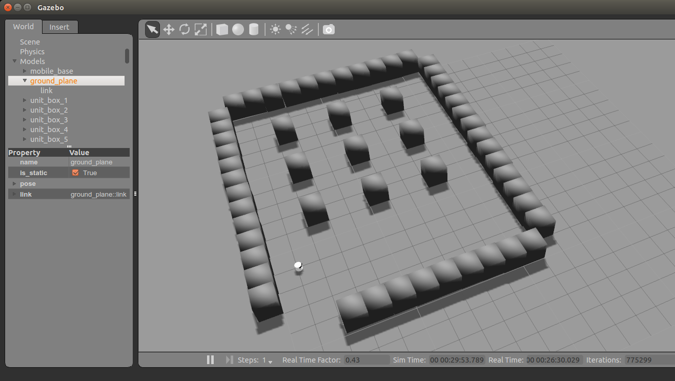
Prerequisites for simulation:The first figure shows the Chefbot simulation in Gazebo.
We need following R.O.S packages to run this simulation.
Following command will install necessary dependencies.
$ sudo apt-get install ros-indigo-turtlebot ros-indigo-turtlebot-apps ros-indigo-turtlebot-interactions ros-indigo-turtlebot-simulator ros-indigo-kobuki-ftdi ros-indigo-rocon-remocon
Setting R.O.S Catkin workspace- Setup a catkin workspace using following instructions.
- Clone the Chefbot repository using the following command
$ git clone https://github.com/qboticslabs/Chefbot_ROS_pkg.git
From the cloned files, copy the chefbot folder into catkin workspace src folder and build the workspace using catkin_make command.
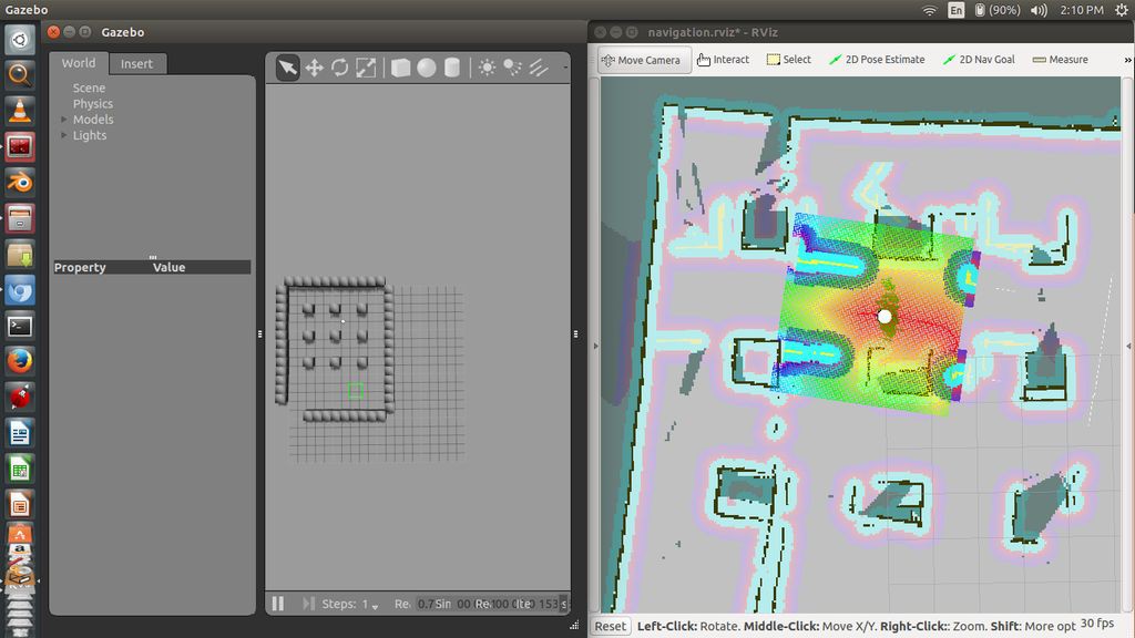
Running Chefbot SimulationLaunch the simulation using the following command
$ roslaunch chefbot_gazebo chefbot_hotel_world.launch
This will open Gazebo simulator with a hotel like environment which is shown in the second image.
Now we are trying to implement autonomous navigation in simulation. First we have to perform SLAM for building map of the environment and after building the map, we have to run AMCL nodes for localizing the robot on the map.
After localization, we can command robot to go into a particular table position for delivering the food and will return to the home position after delivering food.
Performing SLAM using ChefbotWe can see how to perform SLAM and AMCL using the simulated environment.
Start the SLAM algorithm using the following command
$ roslaunch chefbot_gazebo gmapping_demo.launch
Start visualizing the map in Rviz using the following command
$ roslaunch chefbot_bringup view_navigation.launch
We can start mapping the entire hotel by moving robot around the environment.
We can move robot manually using teleoperation, following command can be used for teleoperation for Chefbot
$ roslaunch chefbot_bringup keyboard_teleop.launch
We can generate the map of the environment as shown below. When the mapping is complete we can save the map to a file using following command
$ rosrun map_server map_saver -f ~/hotel_world
This saved map is used for the next step for doing AMCL
Performing AMCL on ChefbotAfter saving the map, close all terminal and start the Gazebo and its nodes using following command
$ roslaunch chefbot_gazebo chefbot_hotel_world.launch
Launch the AMCL node using the following command
$ roslaunch chefbot_gazebo amcl_demo.launch map_file:=/home/hotel_world.yaml
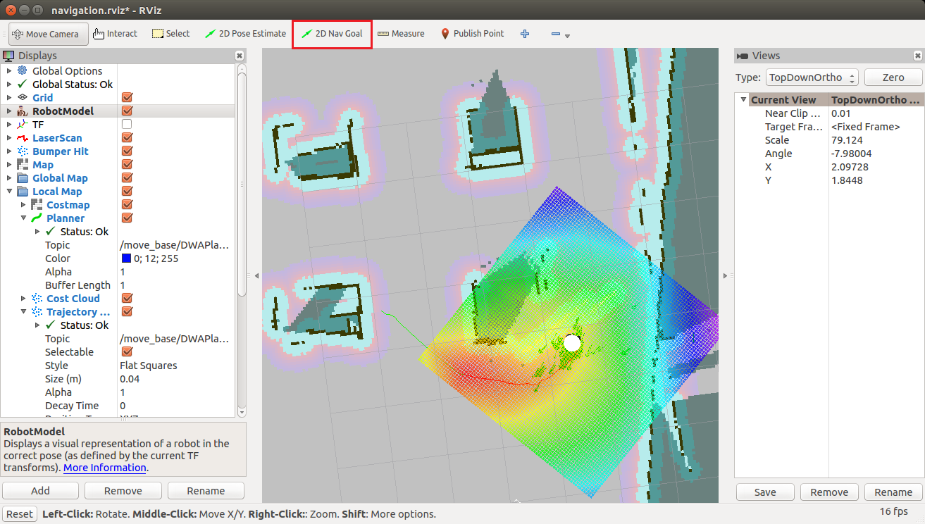
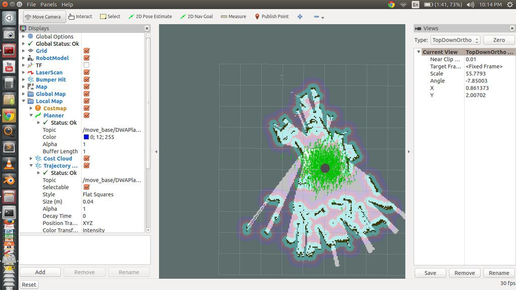
Start Rviz with necessary settings for visualization
$ roslaunch chefbot_bringup view_navigation.launch
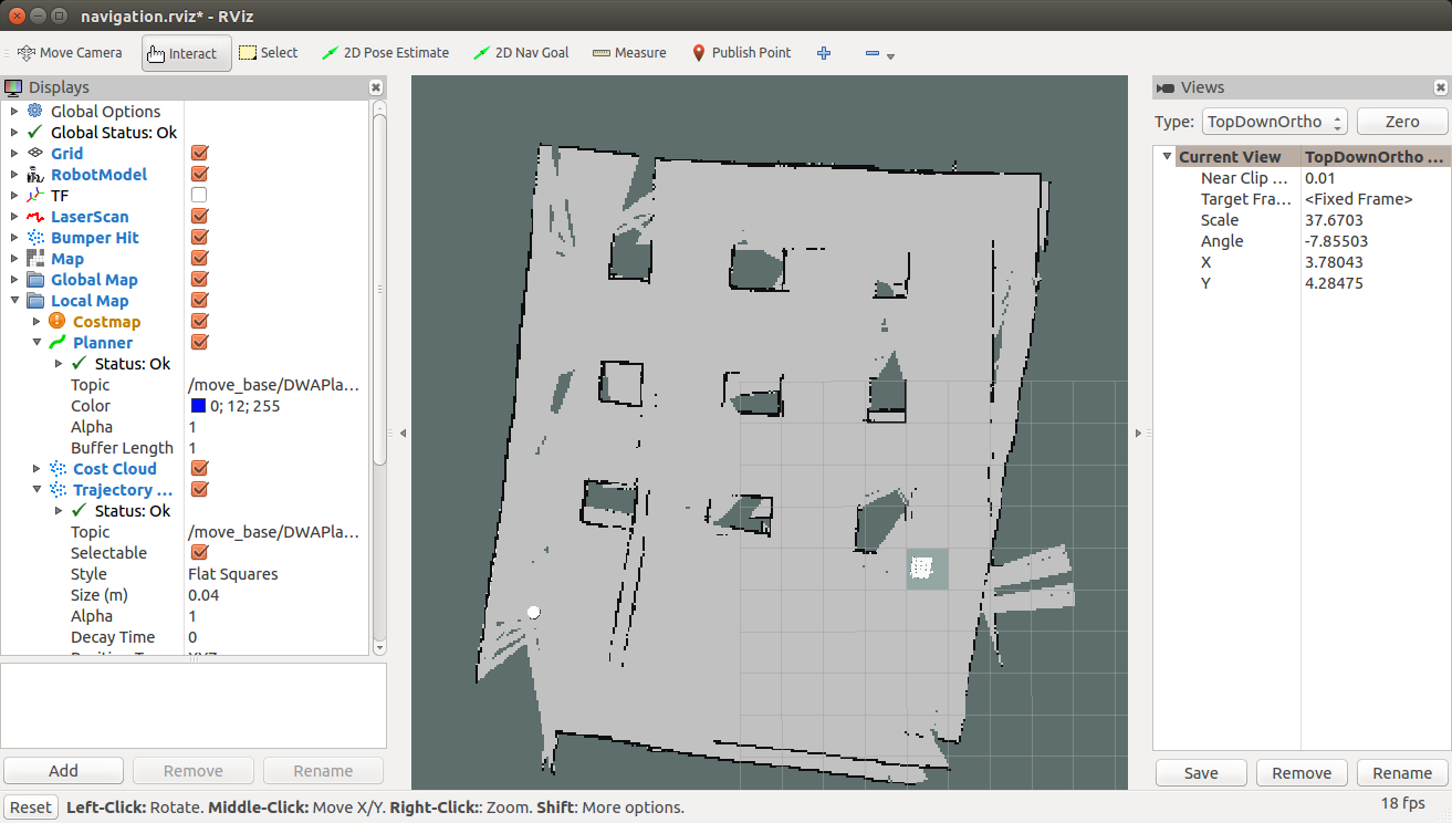
Now we can see the robot is localized on the map which is having the same position of Gazebo.
We can command the robot to go to a particular position inside map using Rviz2D Nav Goal Button.
Using 2D Nav goal button we can give a goal pose to the robot and then you can see the robot will plan a path to that position and move to that path by avoiding obstacles autonomously.
We have performed the simulation of complete robot, now it's the time for designing the hardware prototype of the simulated robot.
-
4Step 4
Step 3: Designing Chefbot Hardware
The robot prototype meets following requirements
- The design should be simple, cost effective
- It should have components which helps to perform autonomous navigation
- Good battery life
![]()
![]()
Component ListComponent List![]()
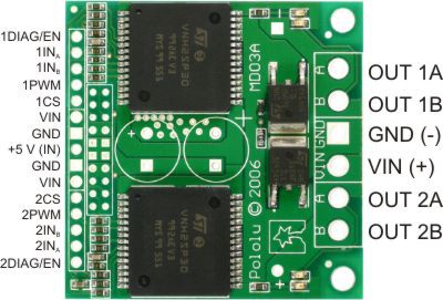
- Pololu DC Motors with Encoder
- Pololu Motor H-Bridge
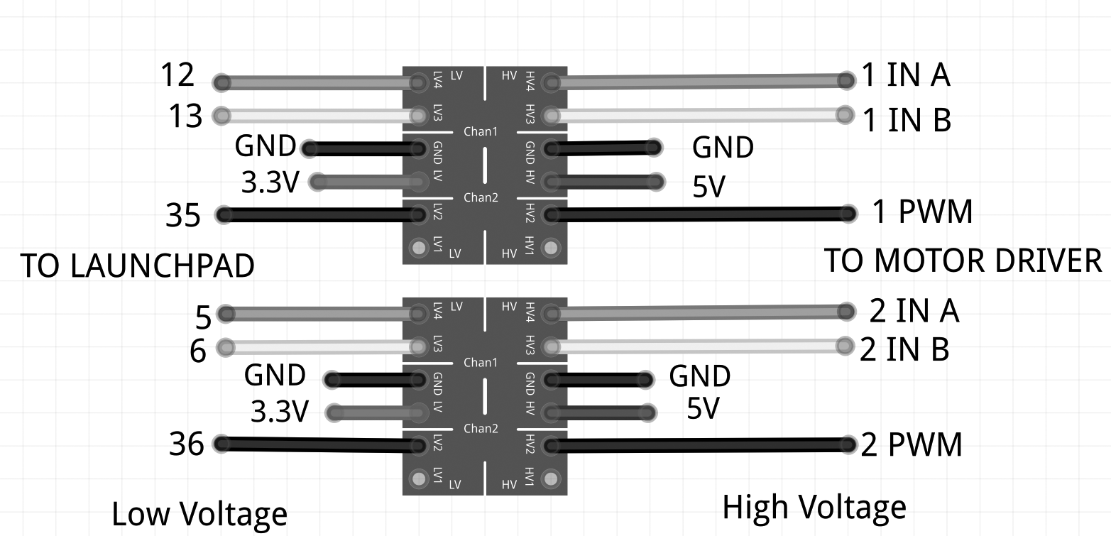
- Level shifter (3.3V - 5V)
- DC Motor brackets
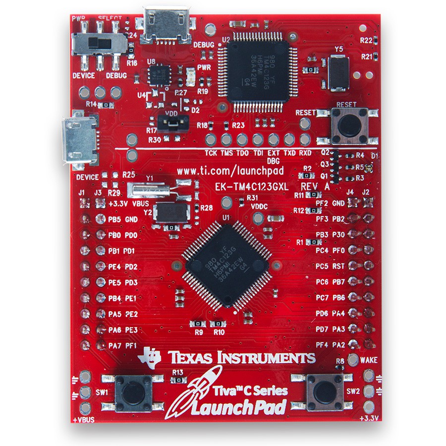
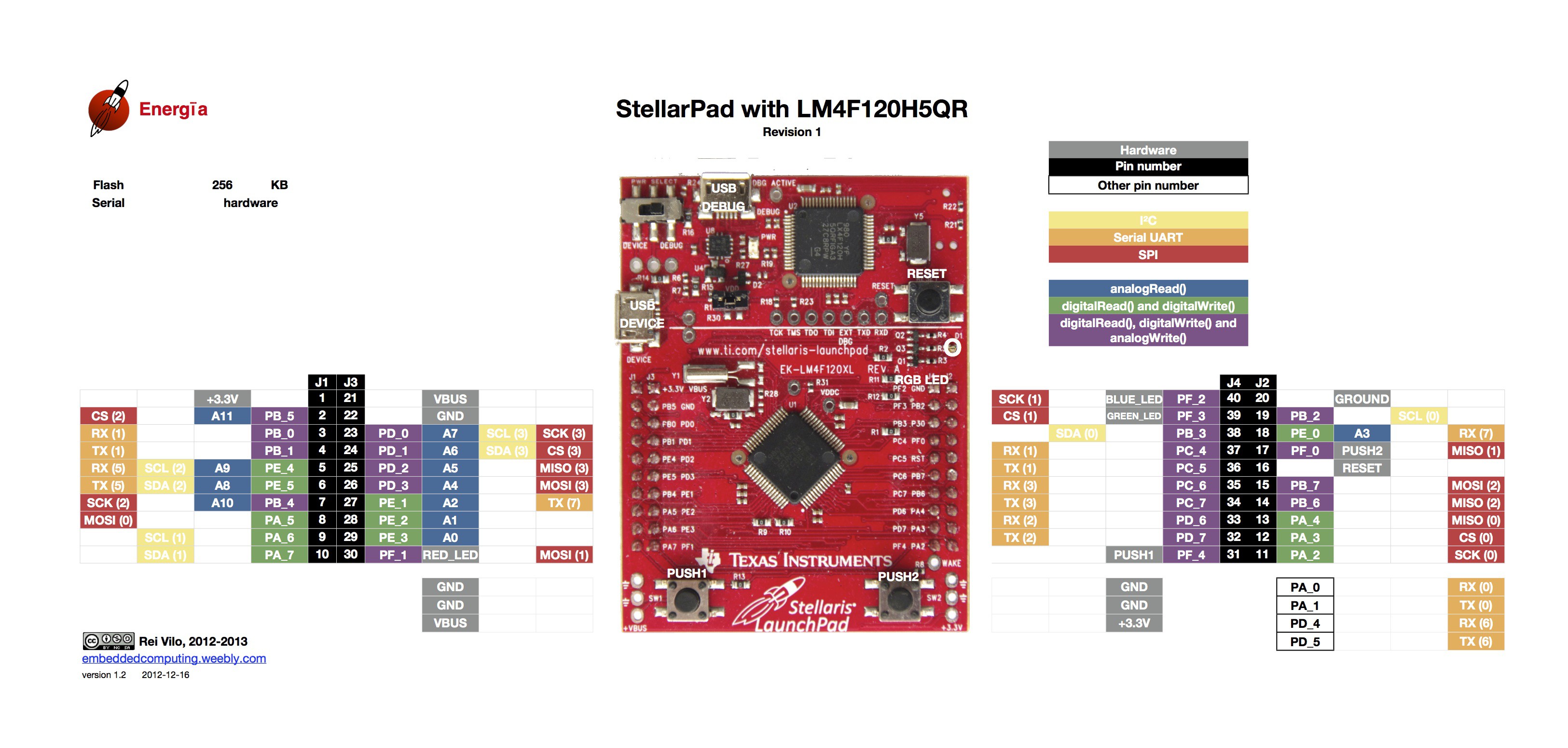
- Embedded Controller board : Tiva C Launchpad
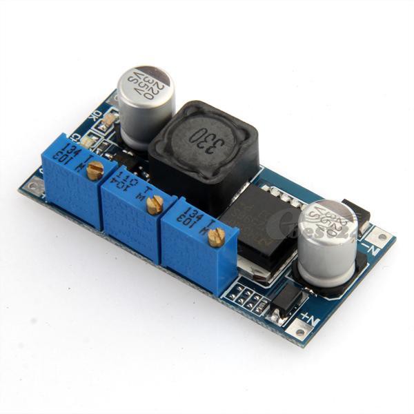
- DC Buck convertor : LM 2596
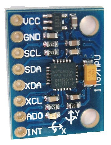
- MPU 6050
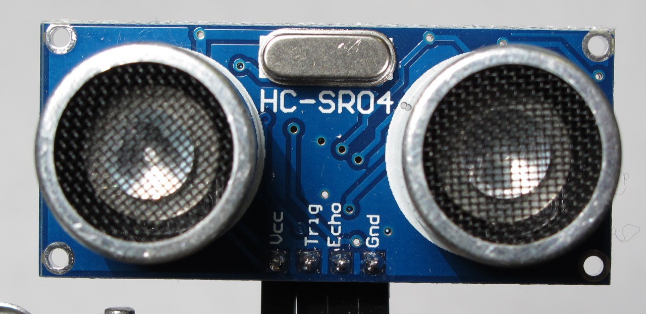
- Ultrasonic distance sensor
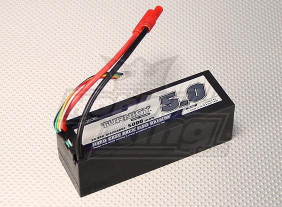
- Battery : Turnigy 14.8Volt, 5000 mAH, 20C
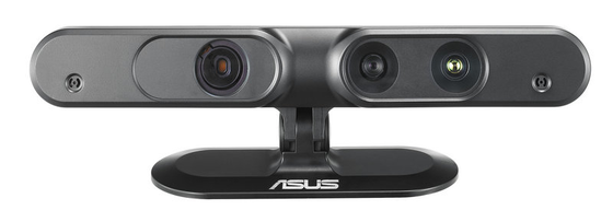
- Asus Xtion Pro
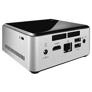
- Intel NUC
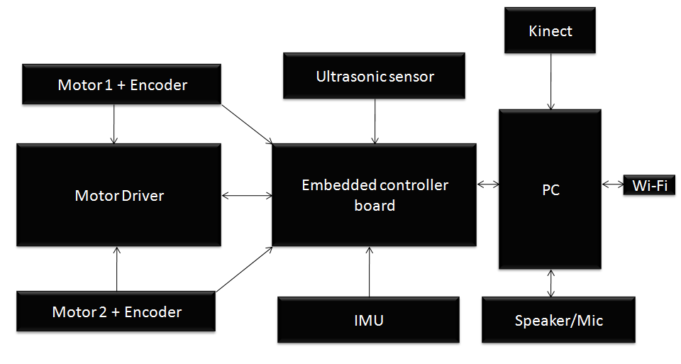
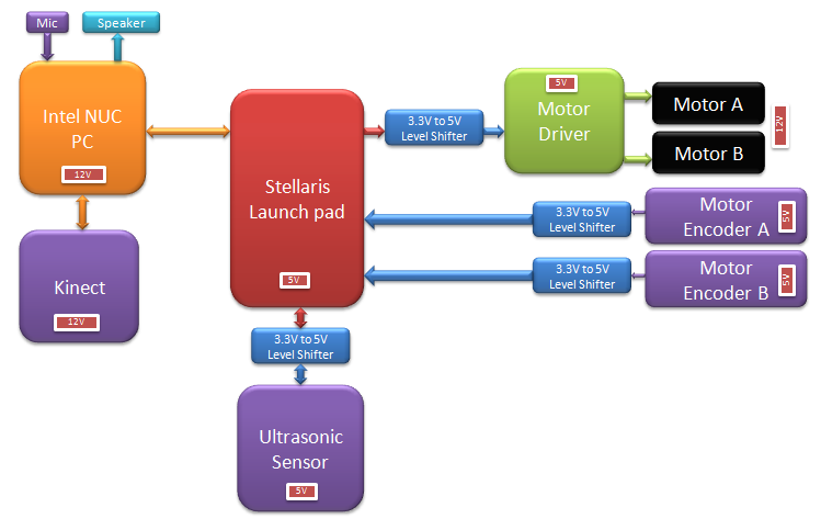
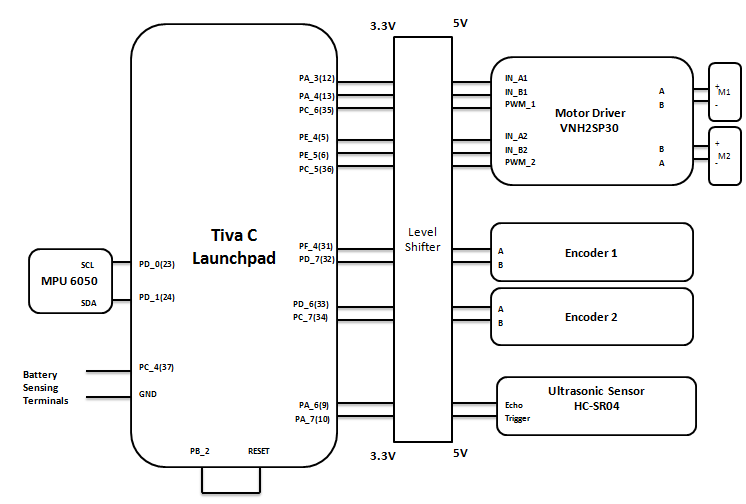
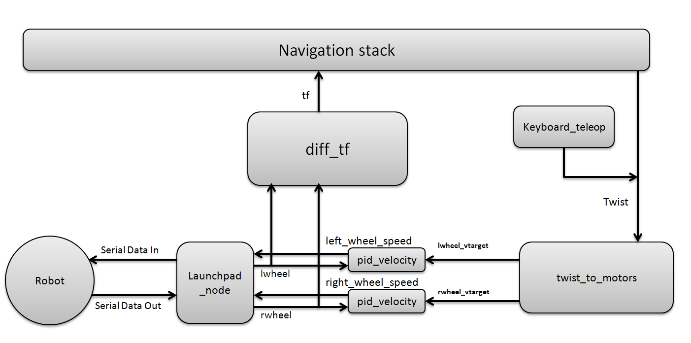
The detailed block and connection diagram of the robot is shown on the images. We can use Asus Xtion Pro instead of Kinect.
![]()
![]()
![]()
![]()
![]()
![]()
![]()
![]()
![]()
![]()
-
5Step 5
Step 4: Interfacing Robotics Actuators and Wheel Encoders
![]()
![]()
![]()
![]()
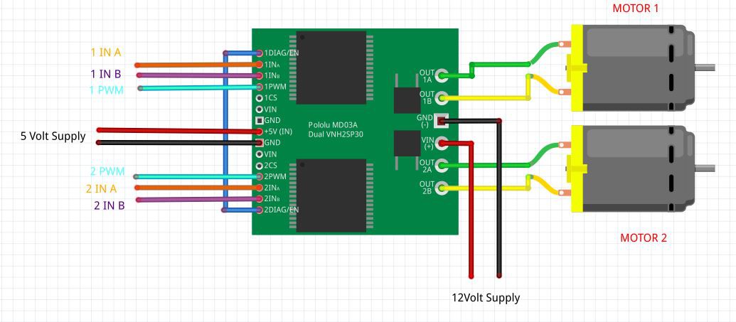
In this section, we can see the interfacing of Motors and Encoder to Tiva C Launchpad. We are using encoders for getting the robot odometry information.
Interfacing DC Motor to Tiva C LaunchpadYou can see the circuit to interface DC motor to Tiva C Launchpad using a motor driver.
I have used Energia IDE to program Tiva C Launchpad . We can use this IDE to program various set of Texas instrument boards. The IDE is a modified version of Arduino IDE and we can program the board using the same programming language that we have used in Arduino.
You can download Energia from the following link. The IDE is available for Windows, Linux and Mac. We are using Linux version.
- Plug the Tiva C Launchpad into Linux system and first select the board and device name as shown in the image gallery.
- The test code for motors is attached below
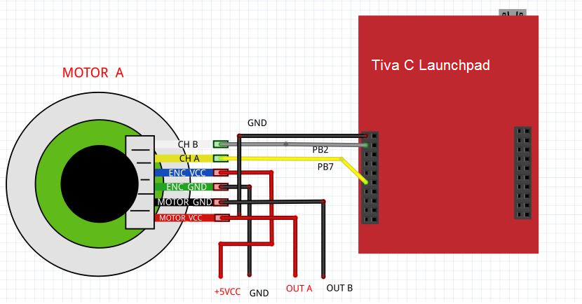
Next step is to interfacing wheel encoders, You can see diagram to interface wheel encoder which is inbuilt in the DC gear motor. The type of encoder is called Quadrature Encoder. The more details about interfacing and working principles of Quadrature encoders are mentioned in the book
The test encoder interface code is attached below
Code : simple_encoder_test.ino
Code : simple_motor_test.ino
-
6Step 6
Step 5: Working with Chefbot Sensors
![]()
![]()
![]()
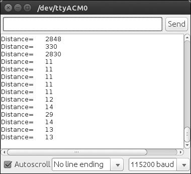
The robot is having ultrasonic sensors which is used for detect collision and also it has a IMU called MPU 6050 which helps for computing robot odometry.
You will get the circuit diagram of Ultrasonic sensor interfacing to Tiva C Launchpad and its code. The expected output of this code is also shown in the images.
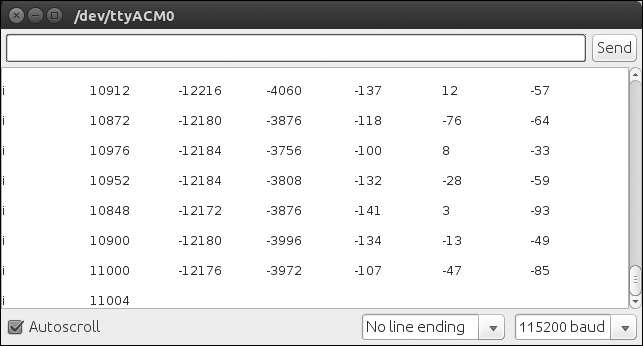
Interfacing MPU 6050 with Tiva C LaunchpadThe interfacing diagram of MPU 6050 IMU is given below.
The pins are given below
Launchpad Pins| MPU 6050 pins
+3.3 V | VCC/VDD
GND | GND
PD0 | SCL
PD1 | SDA
The interfacing code and MPU 6050 library are attached in this step. You have to copy the MPU 6050 library to sketchbook/libraries location to compile the code.
We will get the output in serial monitor if everything works fine. We can also print the sensor values using a python script, which is also attached !!!
-
7Step 7
Step 6: Programming 3D Vision sensors using R.O.S and Python
![]()
![]()
![]()
In this step, we are going to see how to interface a 3D vision sensor such as Kinect/ Asus Xtion Pro in R.O.S.
We can install 3D sensor system driver, middleware called OpenNI and its R.O.S driver/launch files using following command
$ sudo apt-get install ros-indigo-openni-launch
After installing driver, you can start 3D sensor using the following command
$ roslaunch openni_launch openni.launch
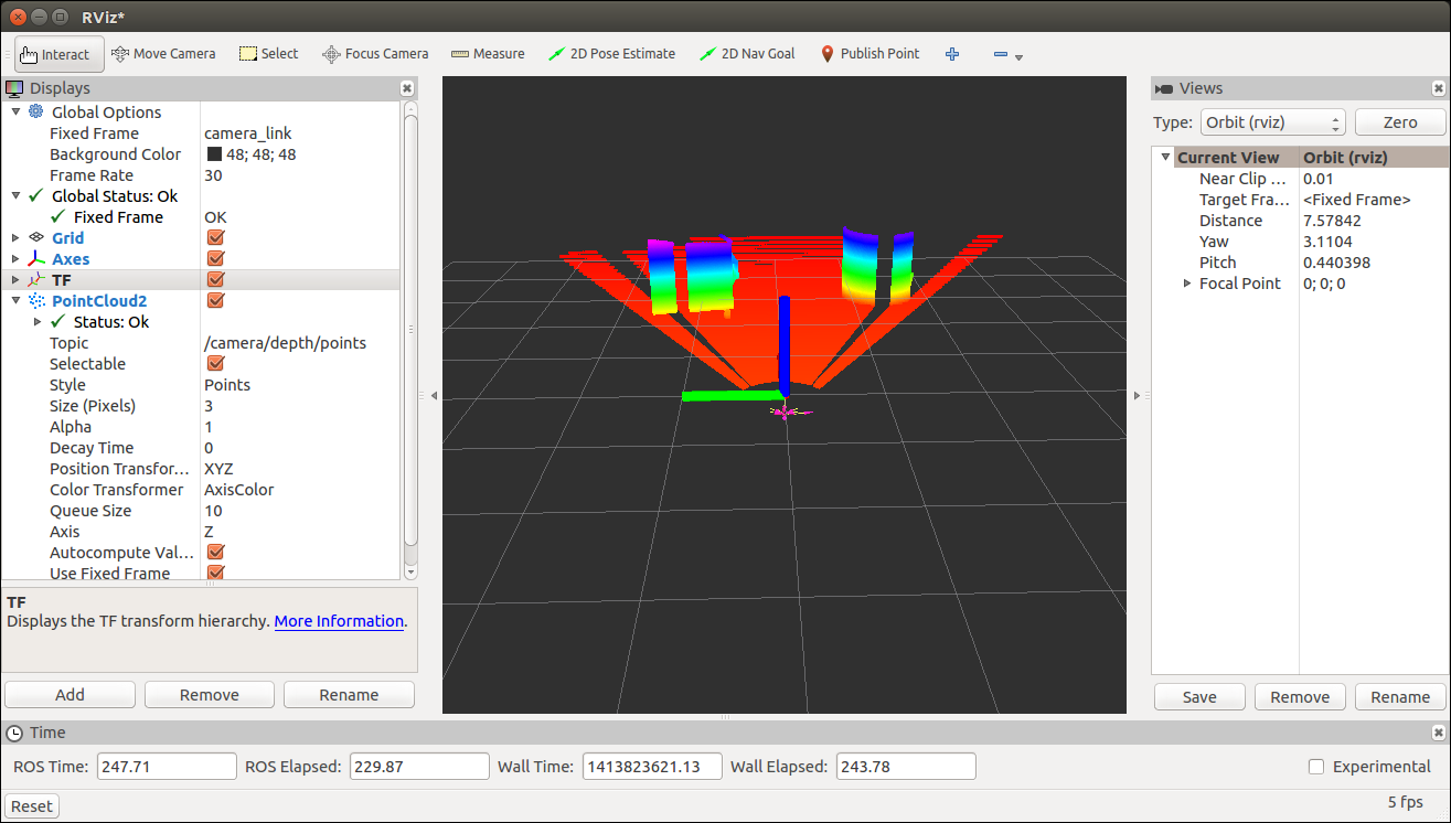
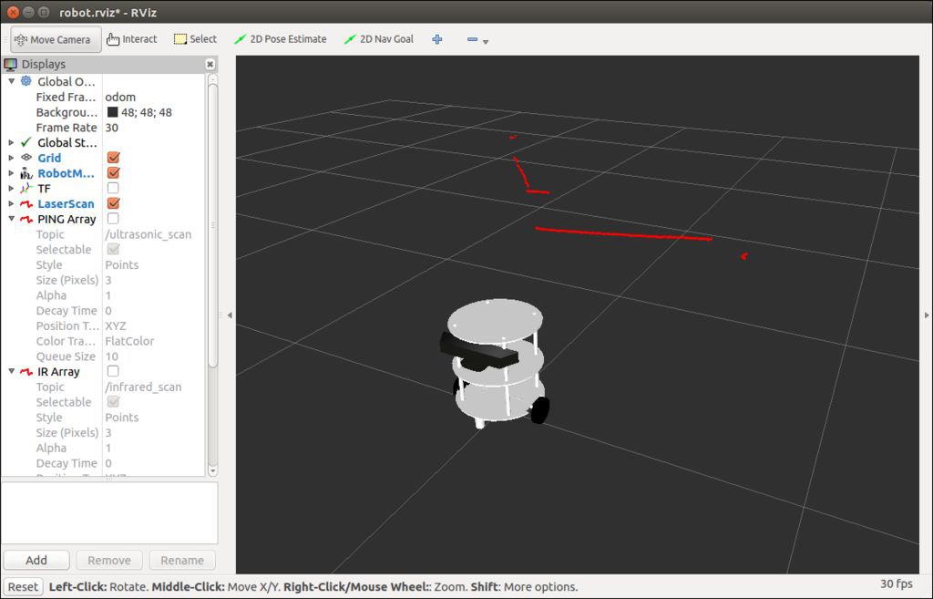
We can view the Point cloud from 3D sensor in Rviz using following command. You can see the Point Cloud visualization screenshot from the image gallery
$ rosrun rviz rviz
We are using 3D sensor for mocking the functionality of Laser scanner which used for performing SLAM. The laser scanner is highly expensive, so mimicking the functionalities of laser scanner using 3D vision sensor can reduce the overall budget of the robot.
The Point cloud data generated not by the 3D sensor but it is processed inside the ROS openni driver.
The point cloud data can be convert to laser scanner data using the following ROS package
Converting Point Cloud to Laser Scanner dataThe depthimage_to_laserscan and pointcloud_to_laserscan packages helps to convert 3D sensor depth image to laser scan data.
You can see the screenshots of converted point cloud to laser scan from the image gallery
-
8Step 8
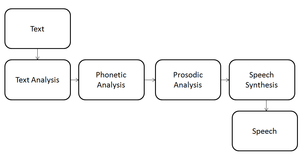
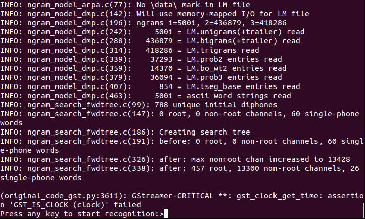
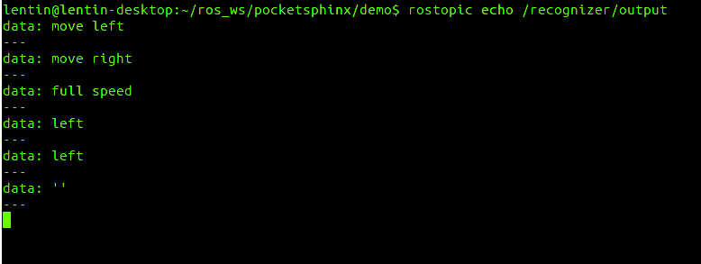
Step 7: Working with Speech Recognition and Synthesis
![]()
![]()
![]()
![]()
![]()
![]()
![]()
The robot can take speech commands from master/user. I have used speech recognition/synthesis libraries to enable this feature. We can see how the recognition and synthesis works from the image gallery.
In the book, i have demonstrated following speech recognition toolkit and its interfaces using python.
Following speech synthesis libraries and its programming is mentioned in the book
In the book, we can also see speech recognizer and synthesis package in R.O.
-
9Step 9
Step 8: Applying Artificial Intelligence to Chefbot using Python
![]()
![]()
![]()
![]()
![]()
![]()
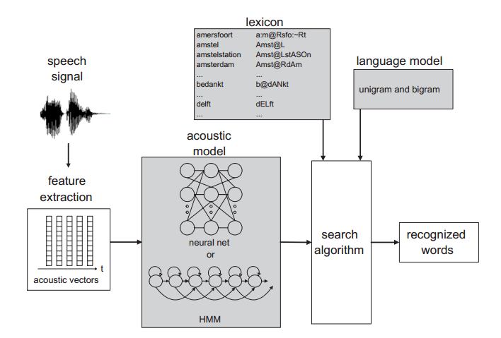
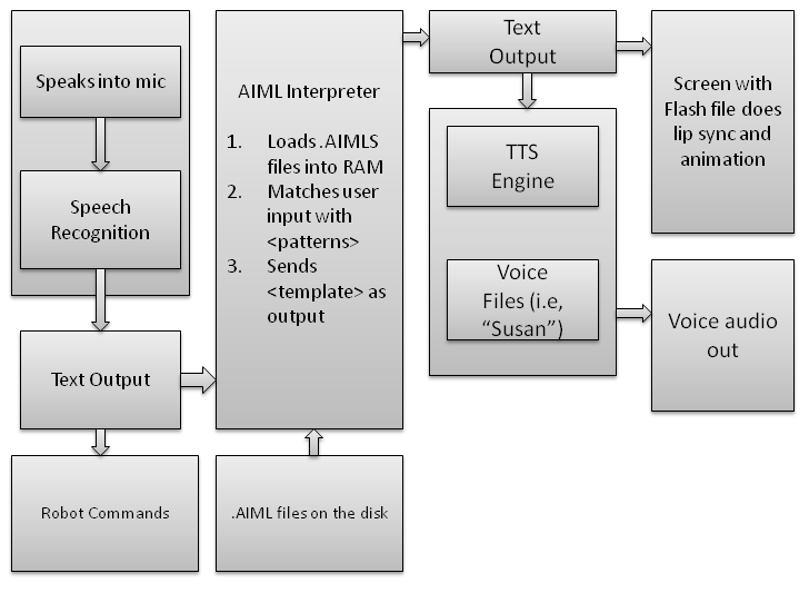
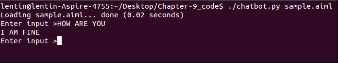
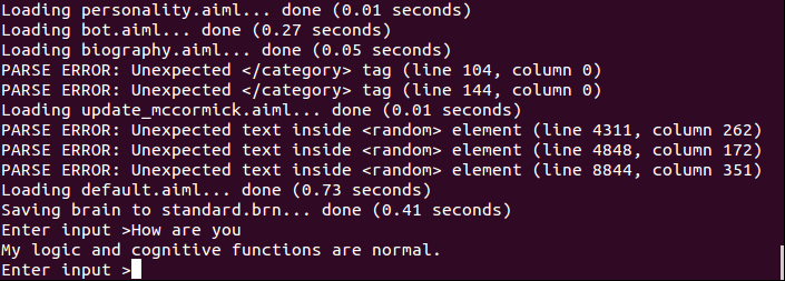
In this section, you can see how to make the robot interactive by adding some sort of intelligence to it. We are using AIML(Artificial Intelligence Mark-up Language) and its Python extension called PyAIML for making the robot interactive.
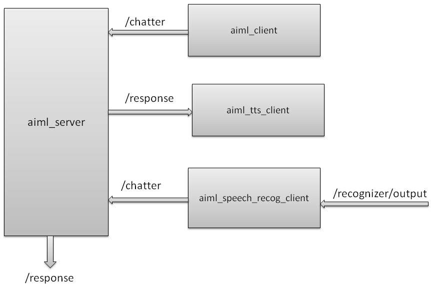
Here we are converting the speech to text and input it into the AIML, after getting the text output from AIML, we can convert it into speech using TTS. The block diagram of this process is shown in the image gallery.
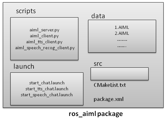
I have also built a ROS package for handling AIML file and the block diagram ofrosaiml package is also given.
You will get the complete code from the code we have cloned already. For getting exercise files, you should check the book codes.
-
10Step 10
Step 9: Integrating of Chefbot Hardware and Interfacing to ROS using Python
![]()
![]()
![]()
![]()
![]()
![]()
![]()
![]()
This section discuss about the complete integration of sensors and actuators to build the robot. You will see the manufactured parts of the robots and its complete interconnection.
The cloned files contain the complete interfacing packages of ROS and firware code for Tiva C Launchpad
DIY Autonomous Mobile Robot
This project is about building an autonomous mobile robot with the help of Robot Operating System(R.O.S) and Python.


Discussions
Become a Hackaday.io Member
Create an account to leave a comment. Already have an account? Log In.
I am using ubuntu mate 18.04 and using ros-melodic .I need to apply this project .
but when execute the frist commen after change the release of ros to melodic as:
sudo apt-get install ros-melodic-turtlebot ros-melodic-turtlebot-apps ros-melodic-turtlebot-interactions ros-melodic-turtlebot-simulator ros-melodic-kobuki-ftdi ros-melodic-rocon-remocon
give me error :
E: unable to locate package ros -melodic-turtlebot
E:unable to loacate package ros-melodic-turtlebot-apps
E:unable to loacate package ros-melodic-turtlebot-interaction
E:unable to loacate package ros-melodic-turtlebot-simulator
E:unable to loacate package ros-melodic-turtlebot-remocon
I know the turtlebot is work with ros-kinetic..Then I change ros-indigo to ros-melodic
Are you sure? yes | no
The project is based on ROS Kinetic. I am running ROS Melodic on Ubuntu 18.04 and hence facing the version compatibility issue.
Here is the question invoked by me on ROS answers:
https://answers.ros.org/question/305453/how-to-get-packages-built-for-ros-kinetic-working-in-ros-melodic/
Are you sure? yes | no
Thinks.
Are you sure? yes | no