-
1Step 1
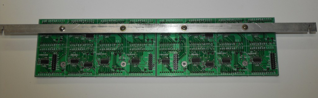
Begin by preparing the displays. The DIY displays require some careful assembly with delicate soldering. Remember to attach mounting hardware before soldering the LED modules as the holes are not accessible from the front afterwards.
![]()
The displays do not come with instructions. Just follow the silkscreen on the board and pay attention to component orientation. The ICs in particular are easy to get the wrong way up. Be sure to double check everything.
-
2Step 2
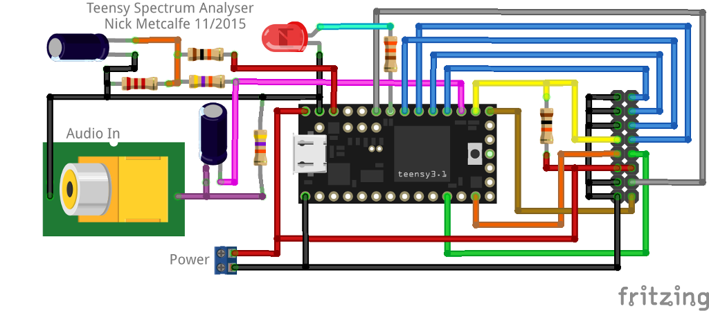
Construct the following controller circuit. Any method will do, but best to use a 16-way plug for the display connector rather than hard-wiring to make fault-finding easier.
![]()
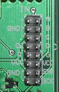
This circuit uses the pinout for the LED display modules mentioned in the materials list. Ensure your pinout is the same or adjust as necessary.
![]()
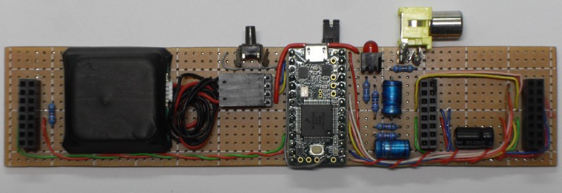
Here's a look at the prototype, ugly but functional:
![]()
-
3Step 3
Download and install Arduino and Teensyduino.
Get the Teensy Spectrum Analyser code and open it with Arduino.
At the top of the file are many options. Find and change the line
const unsigned char m_amountOfPanels = 2;to suit the number of panels you wish to connect.Connect the controller circuit's USB port to the computer and use the upload button to program the Teensy.If all went well, unplug the controller ready for the next step. -
4Step 4
Connect the controller to the input of a single display. Power the controller with 5 volts, either through the USB or with an external power supply.
Note that a USB port may not be able to power more than two display panels. Don't connect USB and external power at the same time or bad things might happen.
At this point things should start happening on the display.
-
5Step 5
Power down the controller and connect all the displays if using more than one.
Connect a line level audio source to the controller's audio input. Power up the controller again. Now you should see the full display.
-
6Step 6
The Teensy Spectrum Analyser code has a bunch of options to tweak how the display looks. Descriptions of these options are in the code itself.
To use these options, change the value in the Arduino IDE and use the upload button to commit the changes to the controller.
Note that some options are quite finely tuned and others are interdependent so be prepared for unexpectedness and remember Ctrl-Z for undo.
Teensy Audio Spectrum Analyser
The Teensy Audio Spectrum Analyzer is a low-cost classic audio spectrum display with up to 128 bands.
Discussions
Become a Hackaday.io Member
Create an account to leave a comment. Already have an account? Log In.
C:\arduino-1.8.1\hardware\teensy\avr\libraries\LedDisplay\LedDisplay.cpp:255:51: error: 'Font5x7' was not declared in this scope
dotRegister[thisPosition+i] = (pgm_read_byte(&Font5x7[((whatCharacter - 0x20) * 5) + i]));
^
C:\arduino-1.8.1\hardware\teensy\avr\cores\teensy3/avr/pgmspace.h:79:55: note: in definition of macro 'pgm_read_byte'
#define pgm_read_byte(addr) (*(const unsigned char *)(addr))
^
Error compiling for board Teensy 3.2 / 3.1.
Are you sure? yes | no
I have these errors
In file included from C:\Users\SaleelMali\Desktop\New project\Teensy SA\TeensySpectrumAnalyser-master\TeensySpectrumAnalyser\TeensySpectrumAnalyser.ino:55:0:
C:\arduino-1.8.1\hardware\teensy\avr\libraries\LedDisplay/font5x7.h: At global scope:
C:\arduino-1.8.1\hardware\teensy\avr\libraries\LedDisplay/font5x7.h:20:48: warning: 'Font5x7' defined but not used [-Wunused-variable]
static unsigned char __attribute__ ((PROGMEM)) Font5x7[] = {
^
'font5x7' was not declared in this scope
Are you sure? yes | no