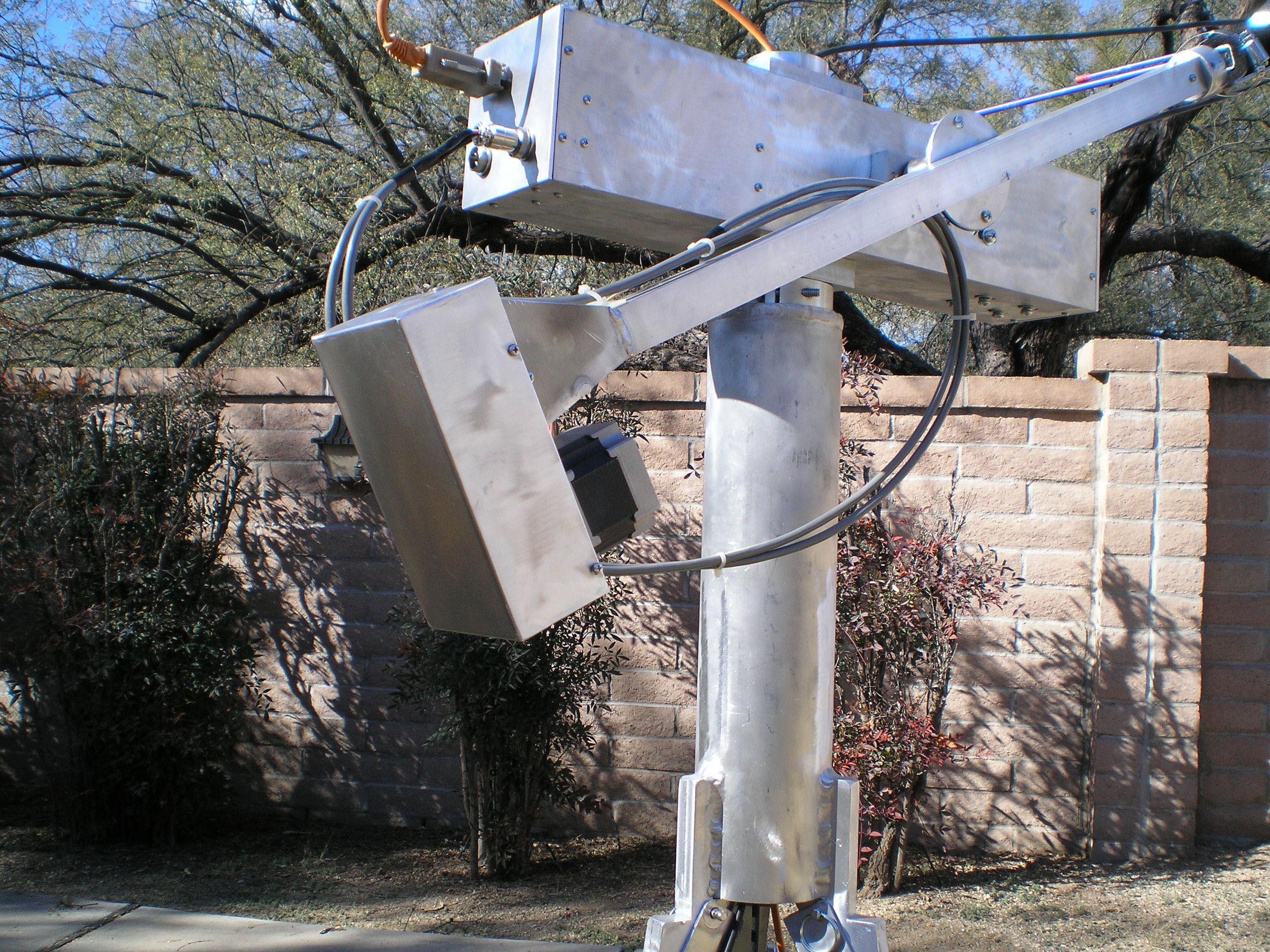
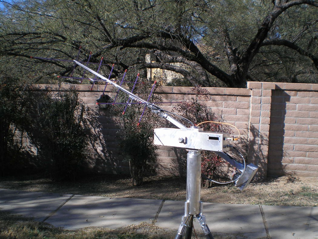
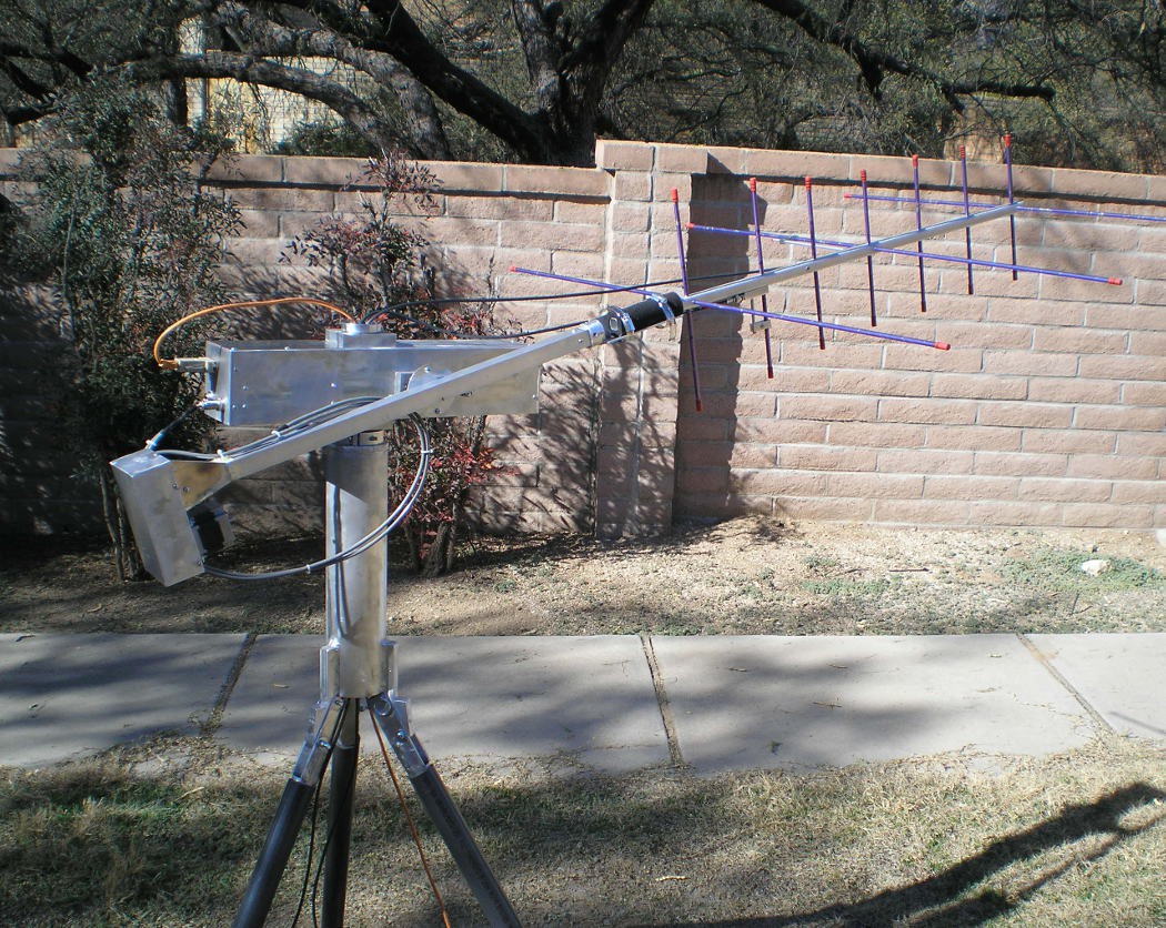
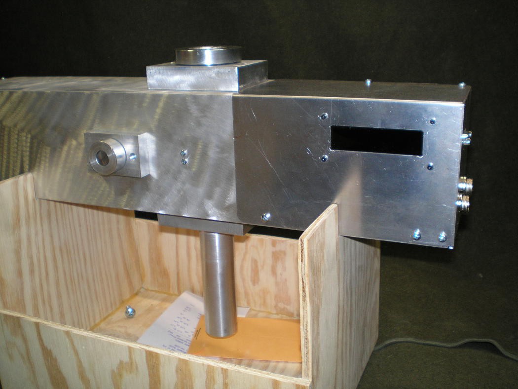
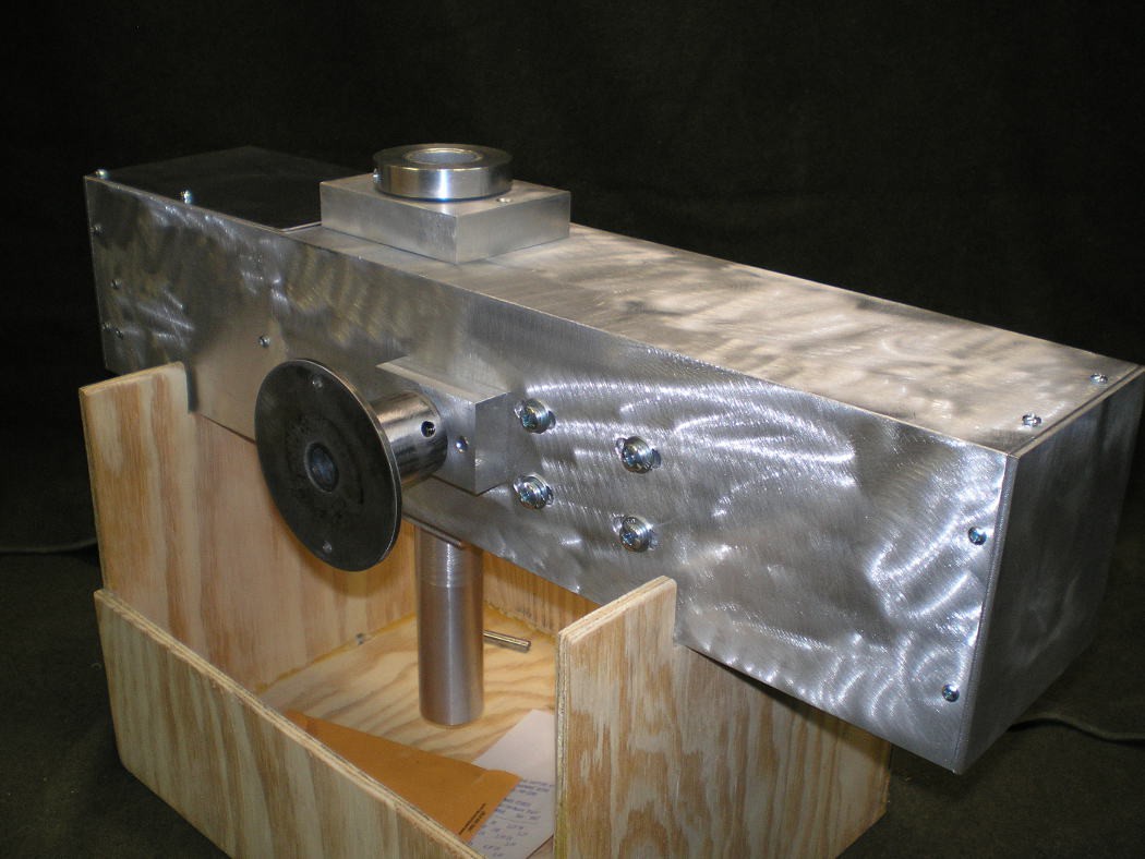
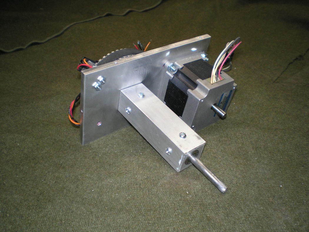
The first design of my rotator was built in 2009 and was a completely different mechanical configuration. The second generation of rotator was done in 2011/12 and the basic configuration was similar to this design: a rectangular tube body with motors rotating the mast and driving the elevation axis. The second generation had all of the belts outside of the body tube and electronics were external also. One version was built for step motor drive and one was built for DC servo motor drive.
The mechanics shown will support Azimuth by rotating the center tube and elevation by rotating the shaft on the side that the antenna arm mounts to. A third axis (not built yet) will allow rotating the antenna on it's center in order to deal with the varying signal polarization caused by the satellite tumbling.
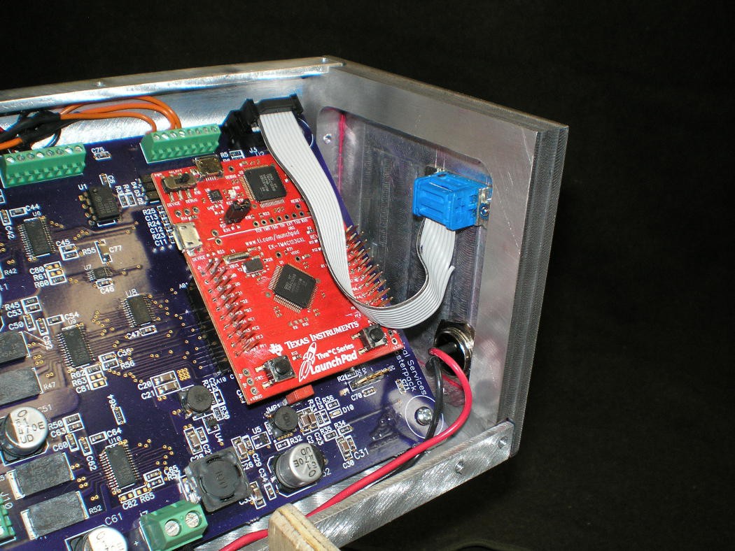
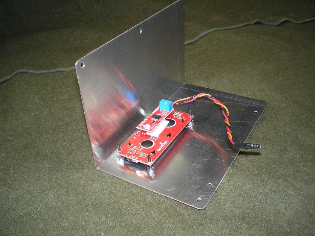
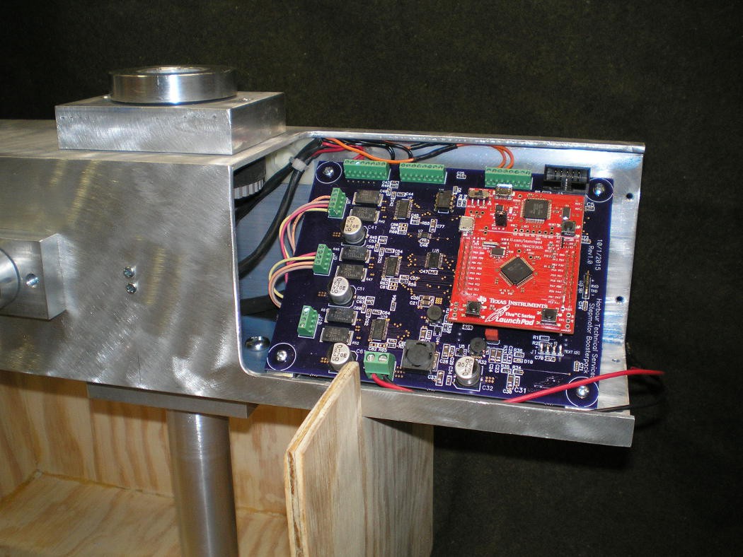
My desire for this version is to have all of the mechanics and electronics enclosed for a more rugged, portable system. I started out very fond of the DC servo implementation, it moves quietly and its current consumption is very low (about 200mA). After building the step motor drive board, I realized that the current consumption of the step motor driven version with 3 motors active, is only about 600mA at 12V in which is still acceptable for battery operation.The step motor version is significantly less expensive too.
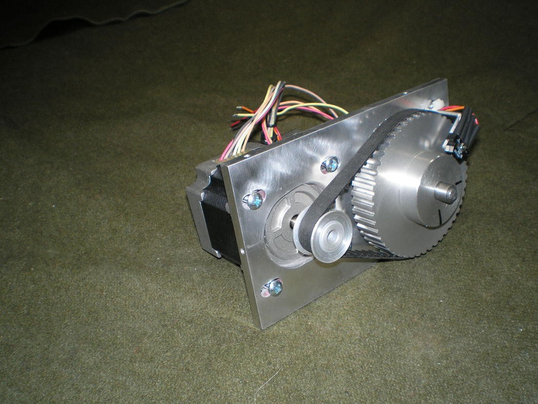
All of the axes use toothed belts for drive with a 4:1 reduction ratio. Running the motors in 1/2 step mode, that results in about 0.225 degrees per step. The drivers will support up to 1/32 micro-stepping, but my casual experimenting makes me think that the holding torque for the motors decreases as the microstep count increases. This bears more experimentation when the construction is finished. In any event, 0.225 degrees is adequate resolution for this project.
 Bharbour

 DrYerzinia
 charliex
There is a guy representing the AMSAT organization that is at most of the hamfests I have been to and he uses a handheld antenna and just points for optimum signal.