-
Antenna Mount Re-designed
08/07/2016 at 17:35 • 0 commentsWhile testing the rotator outside with an antenna mounted and cabled, the performance of the original antenna mount was just not acceptable. The original implementation used a pair of screw hose clamps, clamping the foam rubber grip on the antenna shaft into an L shaped bracket. It was not possible to tighten the hose clamps enough to prevent the antenna from drooping, causing a variable elevation pointing error. I want the antenna shaft electrically isolated from the rotator chasis.
I removed the foam handle grip from the antenna shaft, and machined a clamp from a piece of ABS plastic bar stock that is tightened to the existing L shaped bracket with wing nuts. The new clamp works very well.
The shaft for the theta axis inside the 1" square tube, is a piece of 1/4" steel drill rod. It is not stiff enough in the space between the final fixed bearing and the antenna mount bracket, resulting in a little too much flexing. Re-designing this is going to be a bigger job than the mount clamp. A task for another weekend or 3.
-
Mechanical System is Complete
12/26/2015 at 21:18 • 0 commentsI fabricated the cover for the theta drive belt and home sensor this morning.
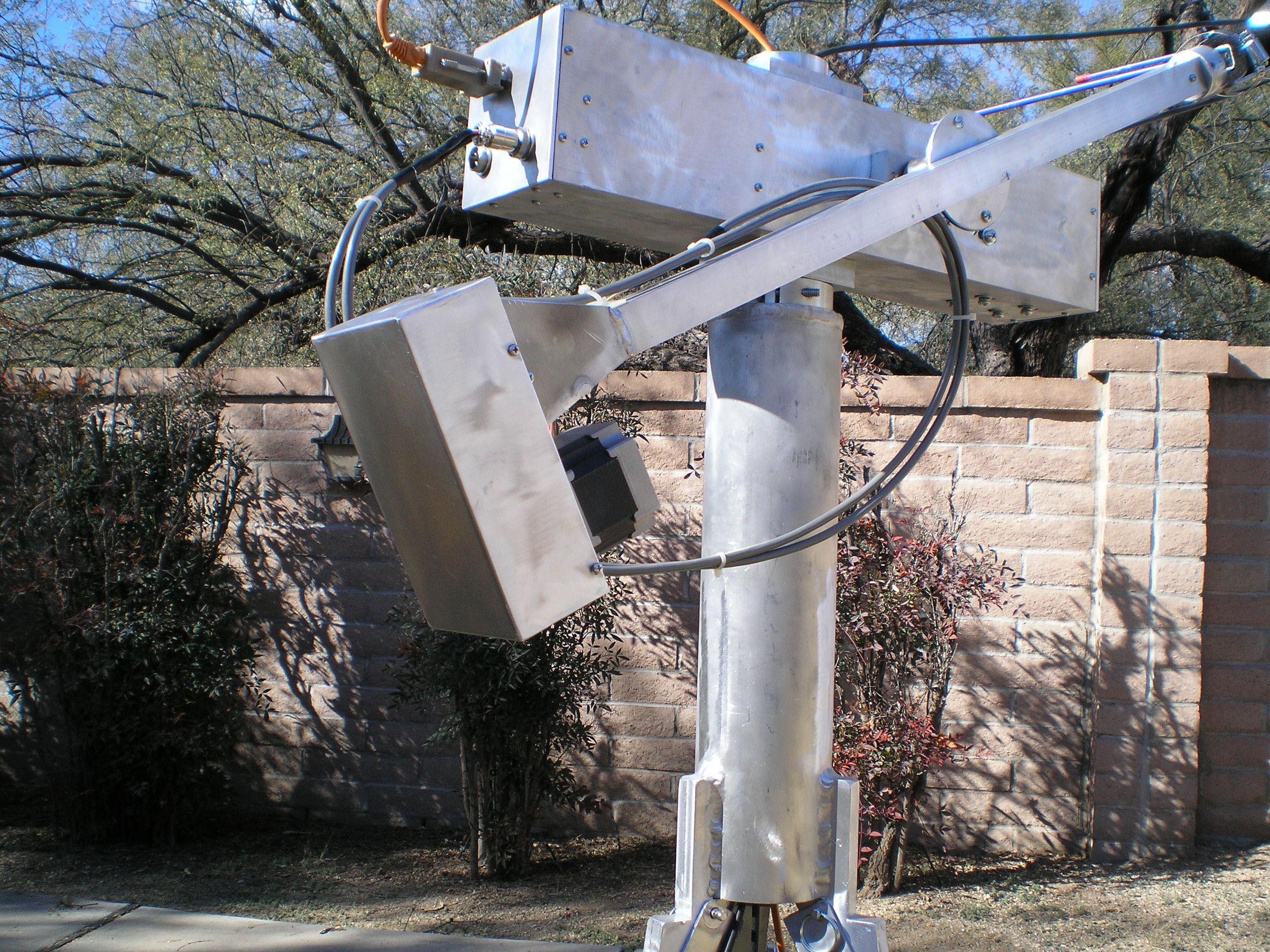
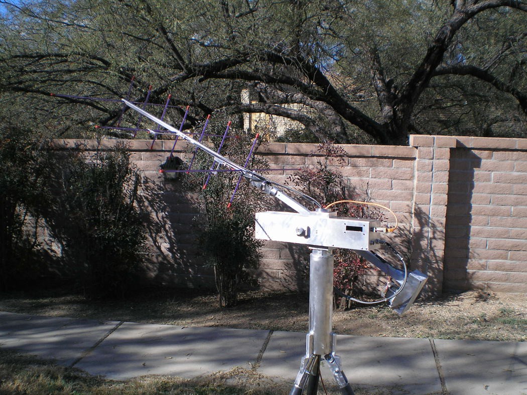
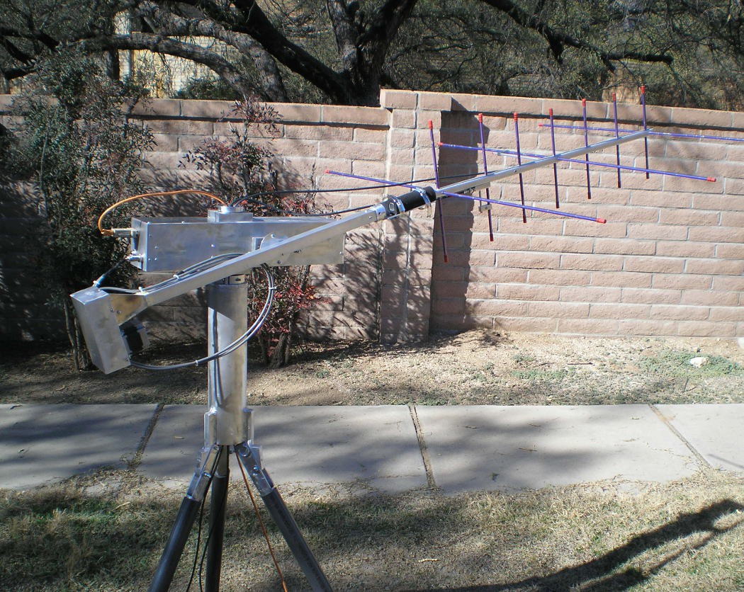
This is the complete mechanical system now. The tripod is interchangable with my previous version, avoiding one more piece to build. The complete system with the antenna is shown below.
For size reference, the wall behind the rotator is about 5 or 5.5 feet tall.
This shot shows the antenna and mount a little better. The antenna is an Arrowshaft Yagi, and the mount is about 6" of 1.5" angle welded to a piece of 1.5" bar stock. A shaft runs from the large pulley seen in previous pictures to the extreme right end of the elevation/theta arm. The antenna mount clamps to the shaft, allowing the step motor to rotate the antenna to accomodate the satellite tumbling in orbit.
The tripod body is a piece of 4" aluminum tube with an end plate welded to the top and the leg mounts welded to the bottom end. A clamp screwed to the top plate allows holding the azimuth tube in a fixed position, so that the whole upper assembly rotates. The legs on the tripod are made to fold up after pulling out the pins just below the end of the body tube.
Cables will go down the center of the azimuth mast tube and the tripod body. Software limits the azimuth rotation to 359 degrees, so twisting up the cables is not a problem.
-
Beginning final system integration
12/24/2015 at 03:11 • 0 commentsI built and balanced the Elevation/theta arm and set the system up in a tripod from a previous build. The good news is that after some messing with, it works. It still needs some more messing with. Mostly, the move velocities are too high. I thumbnailed 15 seconds for a full revolution, but 30 seconds or even a minute would make more sense, given the size and weight of this piece. Another piece of good news is that the motor noise is not as bad as I though it would be. The wooden stand that the initial testing was done in must be acting like a sounding board and making the noise louder.
The move velocity change is an easy fix, change a #define, recompile and load the new image into the hardware.
-
Endcaps, Cover and Elevation Arm mount completed
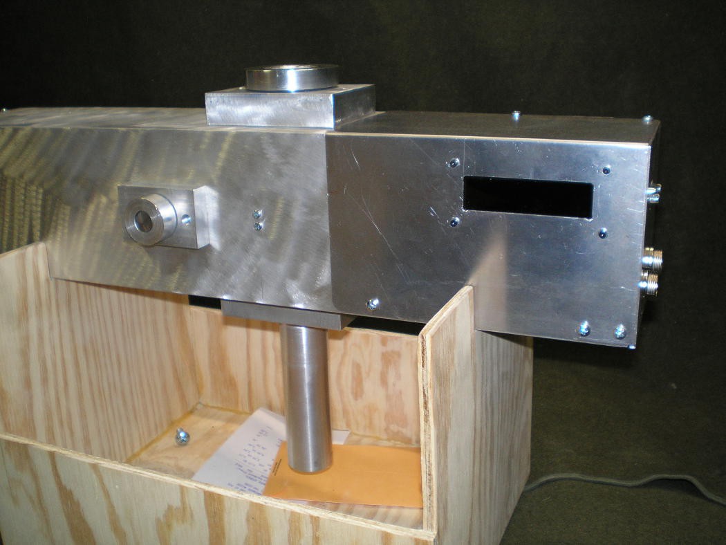
12/20/2015 at 18:33 • 0 commentsThe endcaps for the body tube are done now. one end is just a plug and the other has 3 connectors in it and took quite a bit more machining. A 9 pin D connector (upper one) is the serial data link to control the rotator operation. Power for the system comes in on the lower connector, and a third connector (not visible) behind the circuit board provides the connections for the Theta axis motor on the elevation arm.
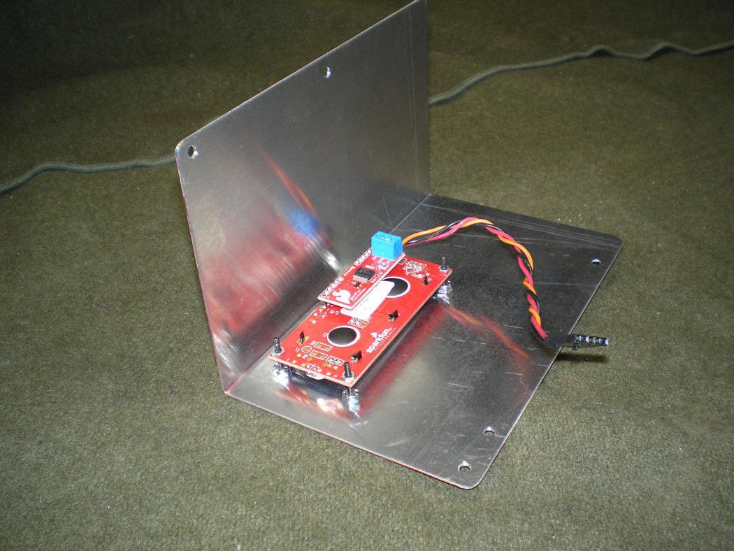
Next, I cut out and folded the cover for the electronics bay. A small LCD (16 characters x 2 lines) is attached to the cover that displays position and status information. In use, the serial link controlling the rotator will be driven by satellite position prediction software (gpredict) that won't show return serial traffic, so I put the LCD in to give some user information back.
![]()
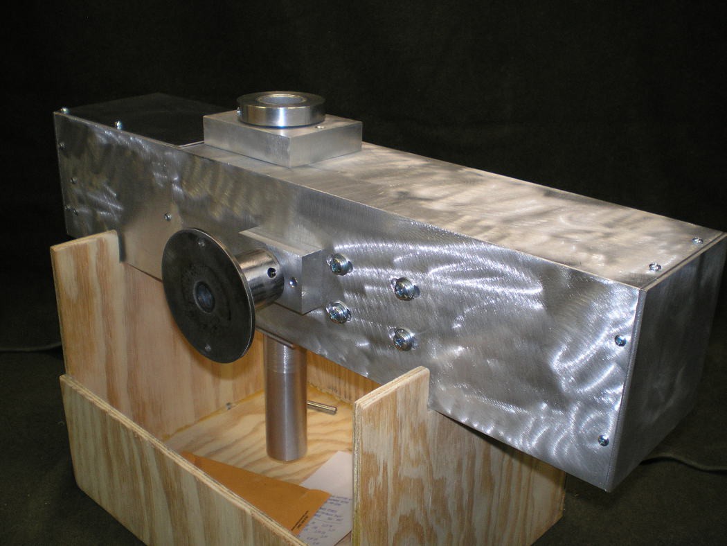
This is the rotator with the cover installed:
Here is the Elevation Arm mount. A similar disk will be welded to the elevation arm and screws will join the arm to the mount.
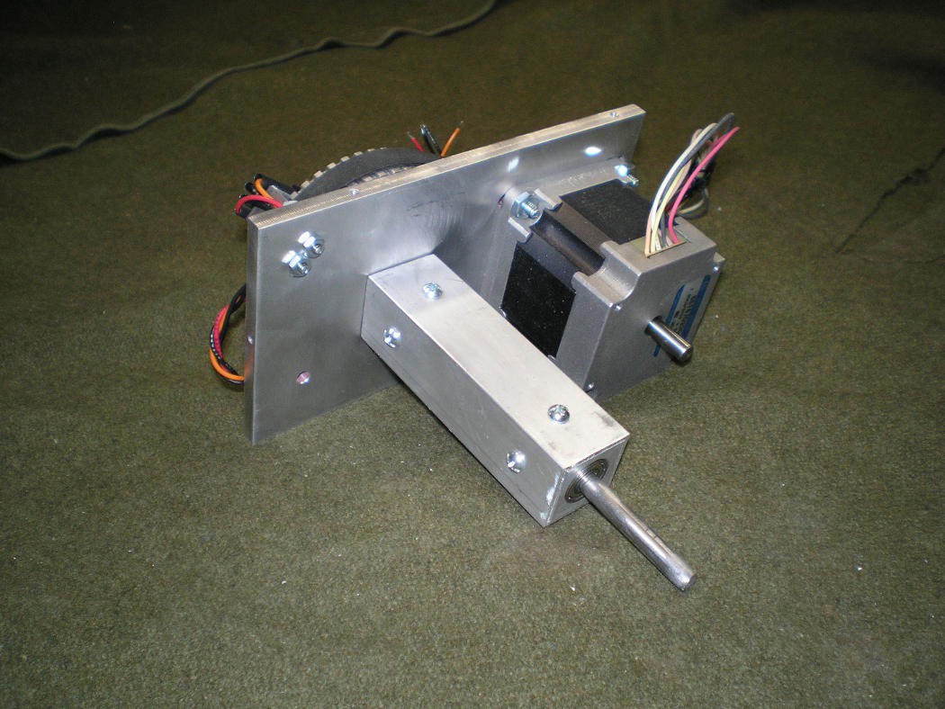
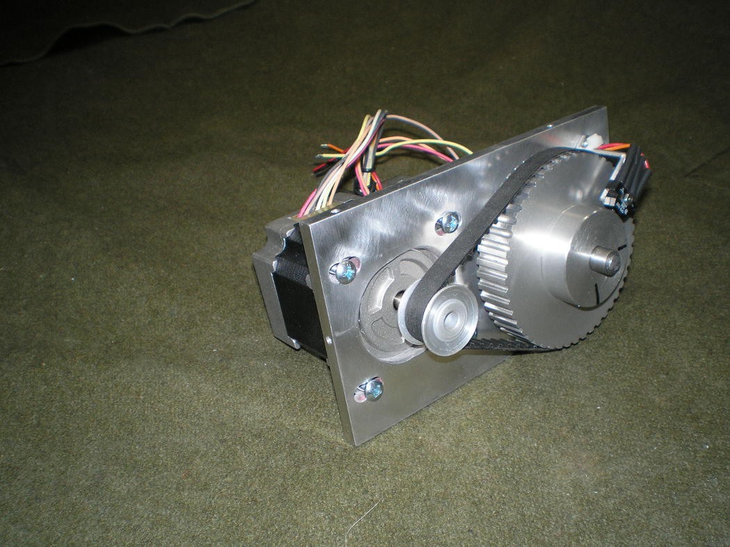
Parts for the Theta axis were the first mechanical things built during the electronics part of the project. I needed a way to Test the home switch operation and the position repeatability for the firmware development. This required mounting the motor, reduction belts and home switch to something, and the Theta axis parts seemed like a good choice.
The short piece of 1" square tubing in this picture is just a mock up of the Theta arm to keep the shaft bearings separated for the software testing. When the I finish the Theta arm, that 1" square tube will be 24" long. A 3" aluminum disk will be welded to the side of the tube for mounting to the rest of the rotator about 1/3 of the way down the tube. It is important that the Theta arm with the antenna attached, balance at the mount plate to keep the Elevation motor loads low.
![]()
A toothed belt is used to get 4:1 reduction (the same as the other axes) and the home switch is installed. The home switch will probably wind up being re-mounted so that it looks straight down at the face of the pulley and a hole drilled in the pulley. Looking at the set screw holes in the hub of the pulley has a problem, there are 2 holes which could give an incorrect home position if the system were powered up in the wrong initial position.
One of the things that was learned from a previous iteration of these rotators is that adjustment for belt slack is required, even when using toothed belts.
Fabricating the antenna mount, the Theta arm and a cover for the pulley and home sensor will complete the Theta arm build.
-
Integrated Electronics and Mechanical Systems
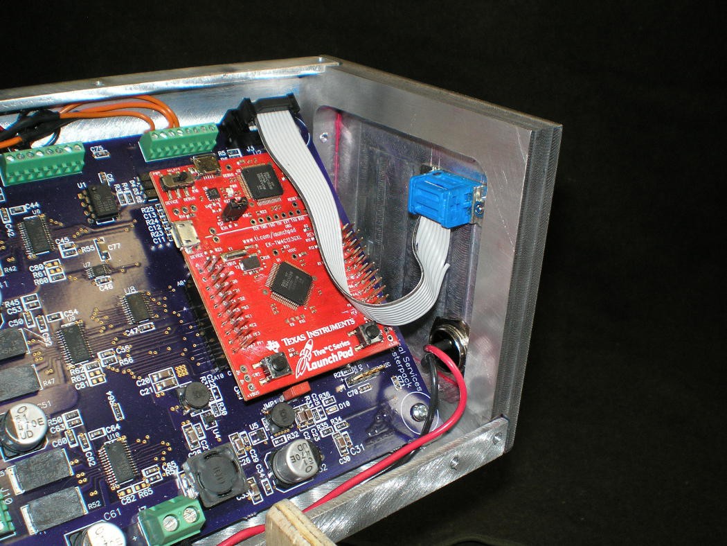
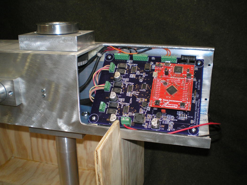
12/13/2015 at 01:11 • 0 commentsI fabricated the board mounting brackets today, mounted up the PCB and connected enough stuff for testing. Both axes move as expected and the home switches work. The board went in at a 45 degree angle so that it would fit, but what started out as sort of a kludge came out nicely. with the board at an angle like this, it is easier to get to the connectors and generally looks good.
The first thing that I noticed when testing this is that it is noisy when it moves. The DC servo version is much quieter.
I have to machine out holes for the connectors on the end cap that sits next to the board and need to make the cover for the board area. Then it is time to make the antenna mounting arm that goes on the Elevation shaft. There is another motion axis down the center of the antenna mount arm, allowing the antenna to rotate on it's axis to accomodate the polarization shift from the satellite tumbling.
The two small phillips head machine screw heads visible to the left of the circuit board cutout area are the mounting screws for the Azimuth home sensor. The sensor is a photoreflective sensor that looks at the face of the Azimuth drive pulley (visible in the picture next to the board) and senses a hole drilled in the pulley.
The wooden stand shown is necesary because this project will not lie flat on a table in any convenient orientation for working on. In use, the round aluminum tube below the square body will be inserted into the top of a tripod mount and the wooden stand not used.
-
The drive belts arrived and fit correctly.
12/10/2015 at 03:16 • 0 commentsThe drive belts arrived today and everyghing fits as is was supposed to. I was concerned that the azimuth belt was going to hit the elevation pulley, as there is very little space in there, but there is 1/8" of clearance as the belt passes the elevation pulley. The home sensors with cables are now mounted to their brackets. While I had the motors out for attaching belts, I put some heat shrink tube over the wires which will keep them much more orderly than the flood of wire that was there when I took the pictures.
The next steps are to fabricate the PCB mount brackets and finish the endcaps. A cover for the PCB area needs to get fabricated too. I haven't decided whether to hinge it or just screw it down. Holes for 3 connectors need to get machined into one of the endcaps, a 9 pin D connector for the serial data connection, a round 8 pin connector for the antenna Theta motor and home sensor, and a 2 pin round connector for DC power in.
I am still undecided whether to leave the aluminum raw or to powder coat the housing. It would look a lot more finished if it were powder coated, but it would show scratches and heavy handling more.
-
Added the Az/El Home Sensors
12/06/2015 at 22:37 • 0 commentsI fabricated and installed the Azimuth and Elevation home sensors today. Optek OPB702D phot0-reflective Darlington sensers work well for this and are fairly small. A 0.250" hole was drilled into each of the 48T toothed belt pulleys and the sensor gets a reflection from the face of the pulley until the hole passes under it and the sensor output goes to logic high.
It may not be obvious from the drawings, but the area around the Az and El axes is really crowded. You can get a sense of that looking at the photo into the center of the tube. It took 3+ hours to get the brackets fabricated correctly and the mounting holes drilled in the body to hold them in place. In the process of doing this, I discovered that I had put the El axis 0.25" higher than designed when I drilled and slotted the body. It is possible that the Az belt is going to hit the El pulley as a result, and I will have to fabricate the body again. The belts should arrive early this week and I will know then. Heres to hoping...
The home sensor bracket design and installation was done directly with the hardware rather than drawn into the CAD drawing at the initial design time. If I did the CAD work in 3D, it is possible that I could have done this at the initial design time, but it was not obvious to me how it was going to fit until I had the parts made. CAD is good, but some stuff I just need to see in real life.
Satellite Antenna Rotator Mechanical System
This is the Satellite Antenna Rotator mechanical system for my step motor driver board project.
 Bharbour