 Moritz Walter
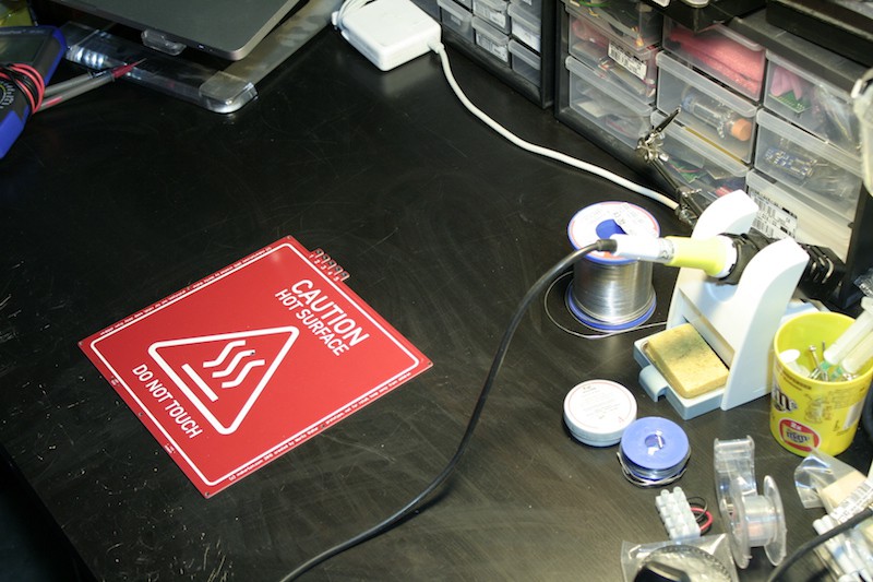
Back from winter holiday, I found some nice blue 0805 smd LEDs in the mailbox, along with some SSRs, fuse holders, RAMPs boards and some other stuff. So yes, it's finally time to test drive a heated bed from the first batch.
Soldering
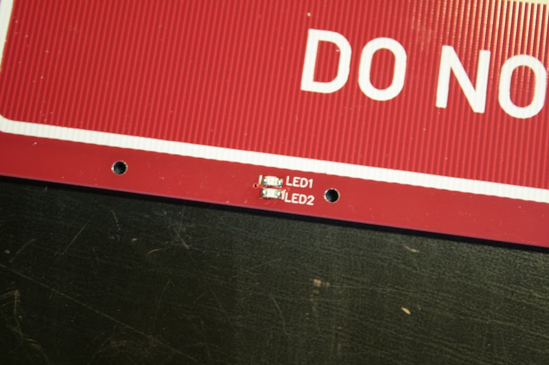
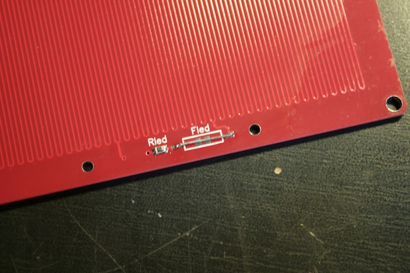
On this first board, I'll only solder the LED circuit and bridge all fuses to test the PCBs thermal stability only. Sorry for the messed up macro shots.
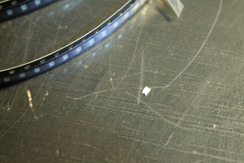
The 0805 LEDs go to the top side..
..while the current limiting resistor..
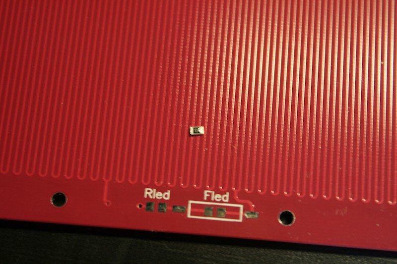
..goes to the bottom, next to the bridged fuse. Note that there are pads for solder bridging, but I didn't use since I want to install the picofuse lateron.
Wiring
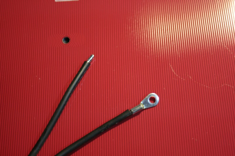
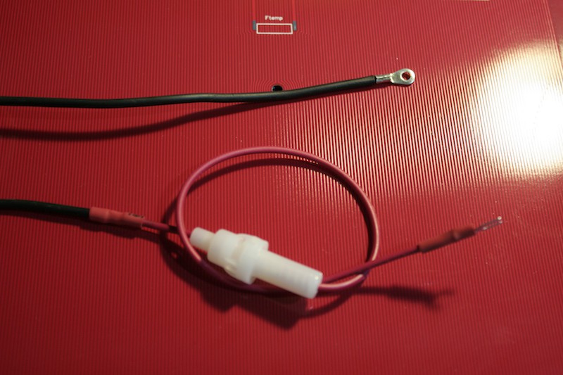
Next step ist preparing the wiring, mostly attaching and insulating cable lugs and inserting the fuse holder.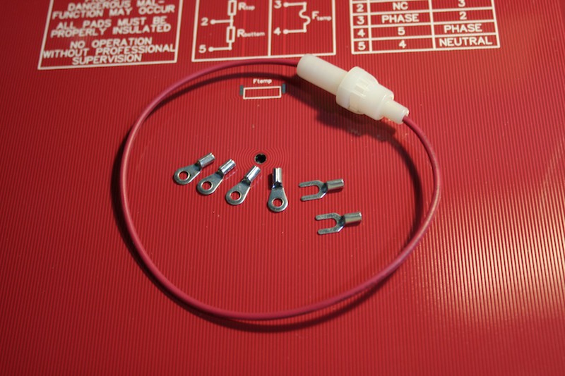
Also, we need a little bridging wire to bridge the pad from the fuse to the phase pad.
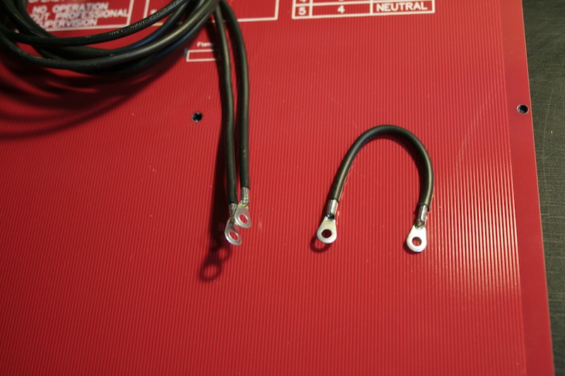
The picture below shows the neutral wire, it goes from the neutral pad directly to the neutral connector of the mains line:
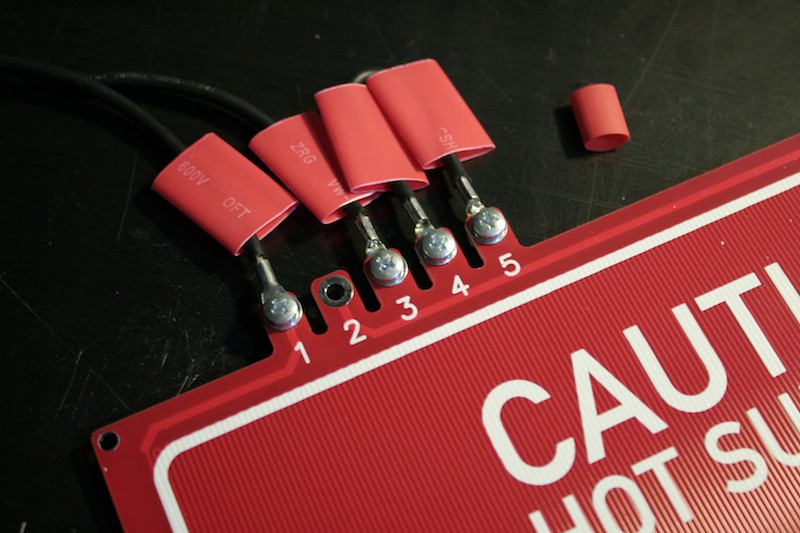
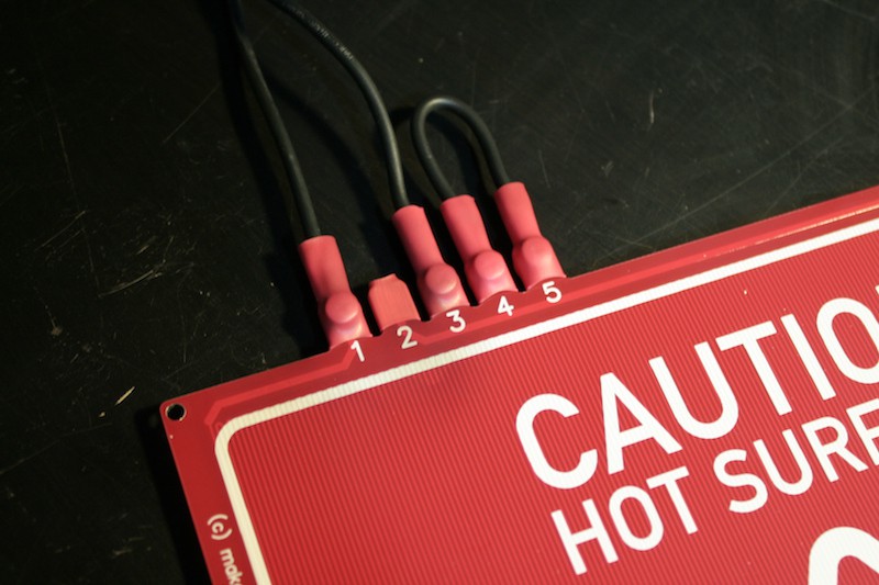
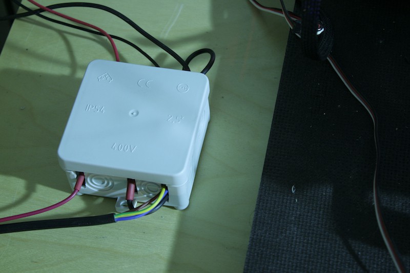
After the screws are tightened, the tube is shrinked over the connections to insulate them safely. High quality heatshrink tube is vital here. Since having the board house mill out 5 fingers from the board is basically free, this is actually a flush and economic alternative to clunky screw terminals.
I love those IP54 boxes. Did you know that an Arduino UNO fits into it just perfectly? They're also cheap and available in many colors :D
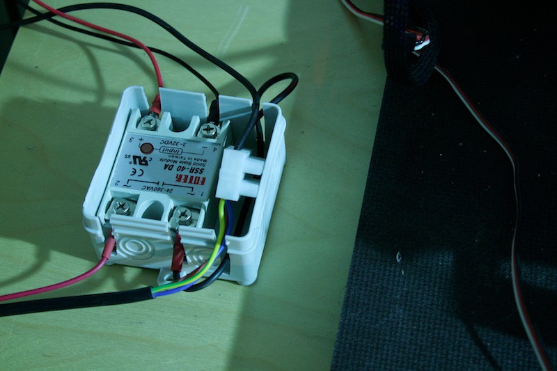
First power up
Since we're not dealing with nice 3.3V logic levels here, bit of faith is required for this step. So I hooked everything up, attached a thermistor to the center of the heated bed using kapton tape and thermal compound, installed the heated bed and powered up the printer. Reading reasonable temperature values of the controller, I then carefully set the heated bed to 30 °C. For a few seconds, both the SSR and the blue led on the heated bed flashed.
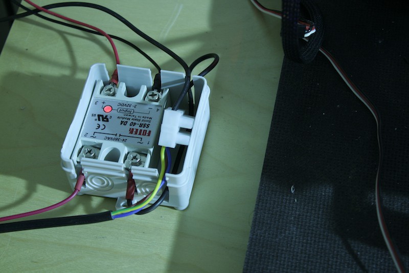
I went on with 40 °C. Still none of the apocalyptic events I was prepared for seemed to happen.
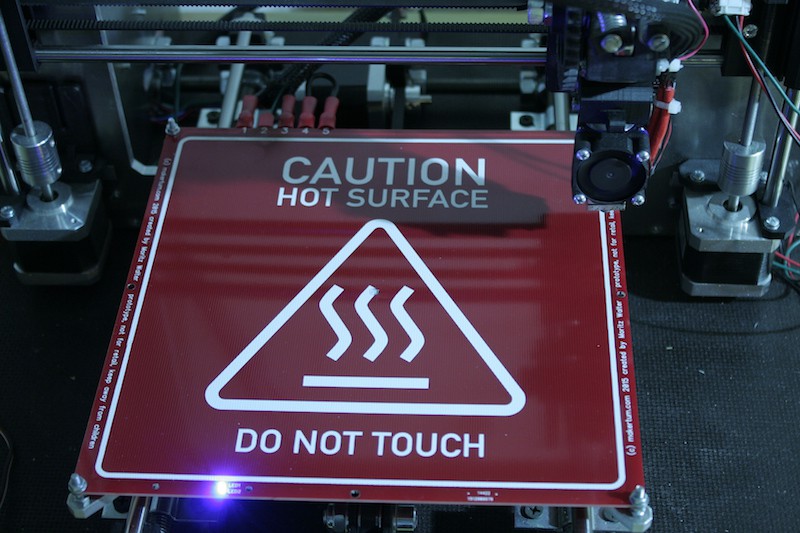
Ok, that made me confident, I started the preheating program to bring the bed to 110 °C.
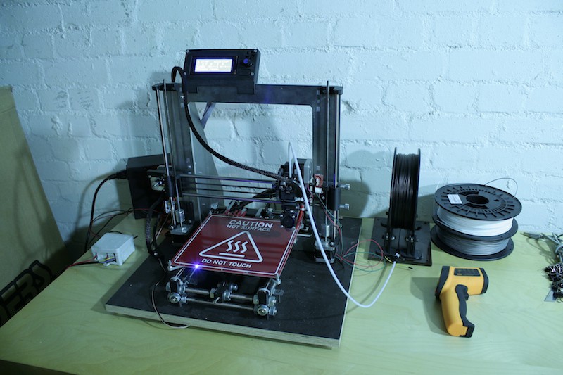
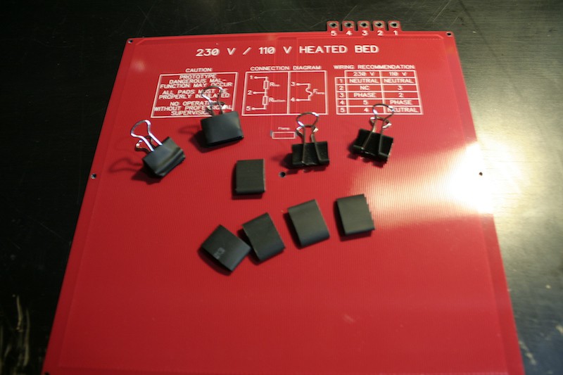
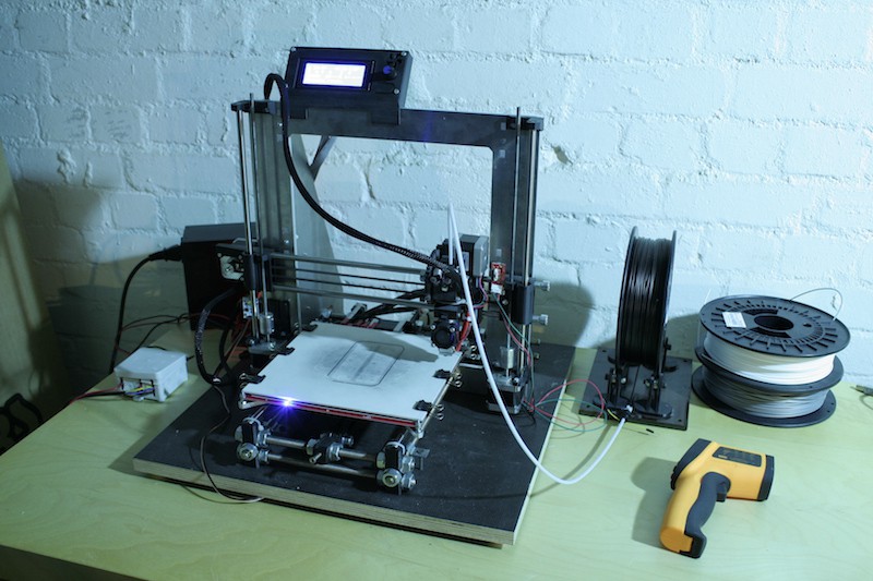
Whooo, the temperature ramps up. Still no apocalypse. But the heatup time is much shorter than expected. It's only a few seconds. The insulated clamps also work nicely on the new heated bed:
Testing
With this up and running, I will now start testing the thermal stability of the PCBs. I'll run this first board at 110 °C for 30 days continuously to see if the FR4, copper traces, solder mask or silkscreen degenerate in any way. More testing setups for testing heatup/cooldown cycles and extrem temperatures will follow the next days.
Further thoughts
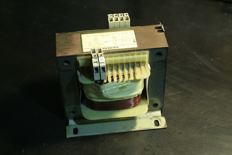
Even though it looks cool with the blue LEDs and gets hot quick, this is still very much unfinished. I.e. the polycarbonate cover for the LED circuit is still missing. The LEDs are too bright, too. I think I'll try a higher value than 1 kΩ for the current limiting resistor next time. The wiring with the cable lugs worked better than expected. Prepping all the wires is tedious though, I guess I need to have them made professionally. I noticed I need to find a better solution for the foldback clamps. The fuses also need to be tested, soon, both their reliability in deflecting the apocalypse and their ability to operate reliable close to the apocalypse. But well, so far that looks really, really good. And look, I can now find a new purpose for that 24 V~ 500W transformer that used to power my old MK2B heated bed:
Discussions
Become a Hackaday.io Member
Create an account to leave a comment. Already have an account? Log In.
nice, a great visual would be a plot of bed temp over time to compare this to the old low voltage heater.
Are you sure? yes | no
Thanks! Great idea, will record one next time!
Are you sure? yes | no
temperature graphs can be found in the latest project log and happy new year :)
Are you sure? yes | no
Great! Those PCB terminals are pretty slick, and the LED I take it is run at some point in the coil-winding, where the voltage is a little more manageable? Cool. Also great plan-ahead adding wiring for 110 or 230.
Are you sure? yes | no
Thanks! Yes, exactly, the voltage differential across the LED cirquit is about 12 V~. Most hair driers use the same technique to drive their fan motors.
Are you sure? yes | no
Might I suggest using reverse mounted LEDs soldered on the bottom side of the PCB so that one cannot touch the LED soldered contacts by mistake?
Are you sure? yes | no
Nice idea! There will be custom milled polycarbonate covers for protecting both top and bottom from unintended touch, but with your reverse mounting technique one might be able to cut the need for a top cover.
Are you sure? yes | no