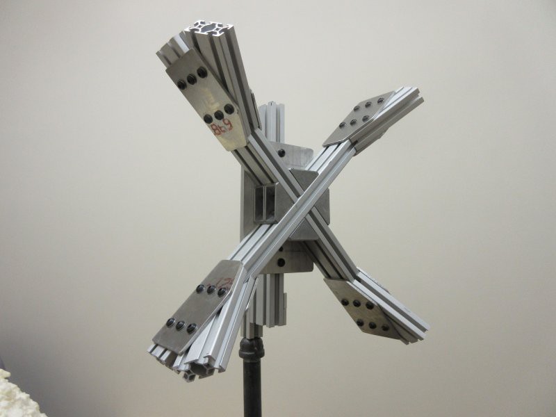
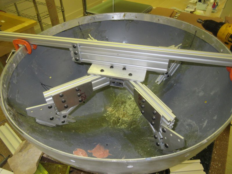
The forward hemisphere housed the main load bearing structure of the satellite. The main weight and load bearing stress were due to the four antennae, each an 8 foot long section of half inch diameter aluminum pipe.
(Yes, I know, not metric parts - but again, timeline and price were dominant here, and these were pretty close.)
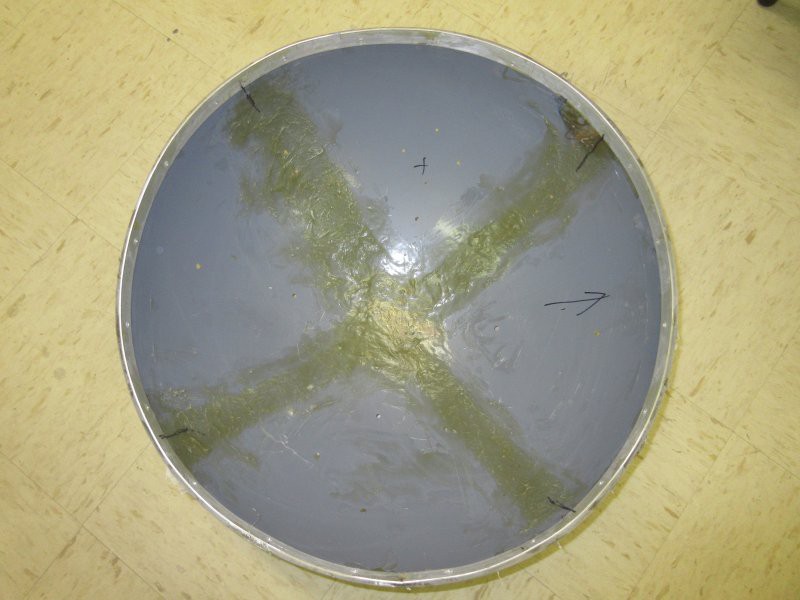
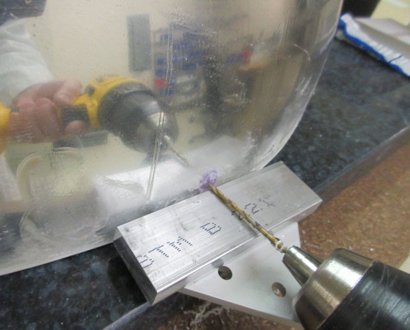
The structure was made of aluminum extrusion, and provided the main support for the antennae, which were bolted through the front hemisphere. The front hemisphere was slightly reinforced with fiberglass, but really only to prevent cracking, not for load bearing purposes. The outer perimeter was reinforced with an aluminum strip, to help maintain the circular edge, and allow for some depth and stronger material for attachment screws for the rear hemisphere to bolt through. The perimeter screw holes were drilled by hand, at precisely marked spots, and using a gauge block, in order to get a consistent offset and precise radial positioning.
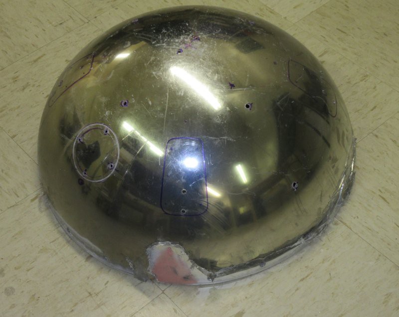
All other screw holes were marked and drilled and countersinked. Some cracks had to be repaired prior to chrome painting.
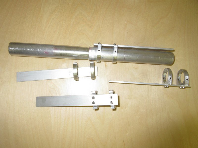
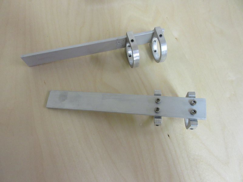
Antenna mounts were made of 1 inch diameter aluminum rod, turned on a lathe to create the taper of the antenna mount insulators (and later painted to look that way), then cut, drilled, and tapped to provide mounting to the frame, and receptacles for the antenna pipes, which were set-screwed in place. Antenna springs and mounts were cut on a Shapeoko 2 and assembled with stainless M3 screws.
 Kenji Larsen
Discussions
Become a Hackaday.io Member
Create an account to leave a comment. Already have an account? Log In.