-
On the loss and renewal of focus
03/21/2016 at 05:08 • 0 comments(TL;DR: spent a few weeks on a tangent eating my own dogfood, finalized PCBs and ordered a bunch)
Spring Break is always full of distractions for me. The kids are out of school, work slows down a bit, and South by Southwest takes over Austin, TX. A few weeks ago I got an email from @Sophi Kravitz asking if I might have any hacks I could bring for a panel she was giving at SXSW Create. Naturally I wanted to show off this project, but it hadn't occurred to me 'til then that I had built exactly zero projects using the WiFi Pants board.
The board isn't that interesting by itself or on a headless Pi, so I wanted it to do something flashy. It needed to be battery-operated to show off the boost converter. So I turned to my junk bin for inspiration, and made a simple LED scroller with the LED matrix from Sparkfun's BadgerHack swag they gave out at last year's SXSW (thanks again!):
I... uh... went a little crazy on this. I didn't expect the show-and-tell to be anything more than what it was: a short demo during the panel. But somewhere along the line I got it in my head that it needed to be a polished looking gadget and not a pile of boards and bodge wire.
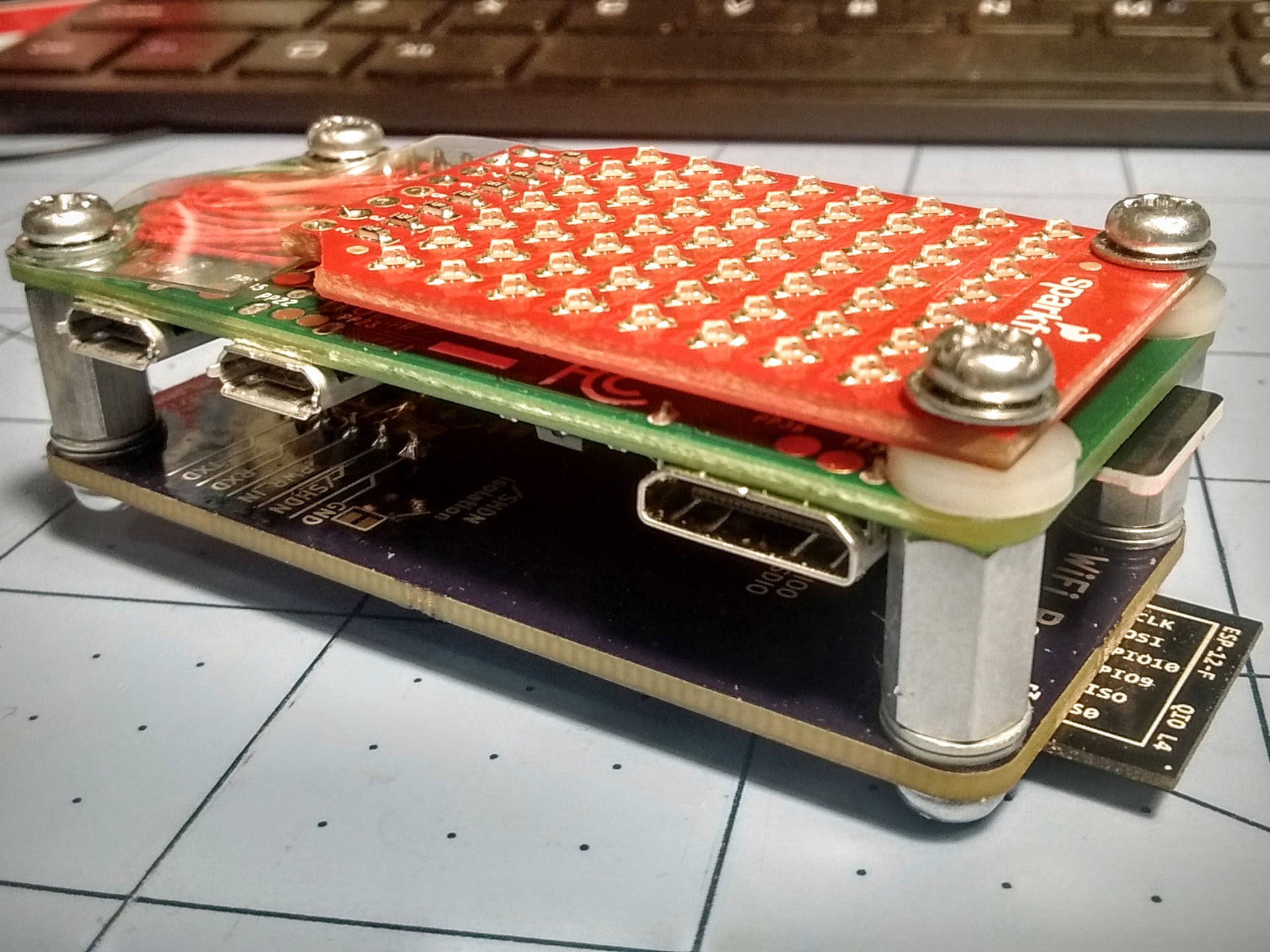
I spent a few late nights building the board stack and designing a 3D printed case. The Sparkfun LED array has mounting holes on 23mm centers, conveniently matching the Zero's screw holes, so I scrounged some washers, standoffs, and screws from my junk box and point-to-point soldered the array to end up with this:
![]()
Initially I wanted to fit a small LiPo pouch in between the Zero and Pants board, but I ran into a few problems. I couldn't just go down to the local hobby shop and grab a battery for a nano quadcopter. I needed a protected cell to compensate for forgetting the UVLO (under voltage lock-out) programming resistors on the switcher on this board rev. Failing to have either cell protection or UVLO on the switcher could drain the battery too far and lead to surprise fires of the sort I'd like to avoid. Unfortunately there seemed to be a run on cells with the characteristics I wanted: reputable seller, fits in a 45x23x6mm volume, has protection, big enough for 1hr runtime (>=400mA), and fast enough shipping to get here in time. It seems that the sorts of batteries I wanted were all snatched up by hackers making one of the DIY Zero-based Gameboy projects.
I ended up sticking a 3-AAA battery holder to the back of the case. I used 750mA NiMh cells which consistently give 2:15 runtime with the scroller running constantly. It wasn't as pretty as it would have been with a LiPo, but it worked and was likely safer. I had to make changes in the case model to make the battery connector accessible from the outside, but otherwise it worked well.
The software is all Python. I could have done a C userspace daemon or kernel driver to make the display scanning smoother, but I didn't have time and figured a 1GHz CPU could handle it. It is multithreaded though, with the display scanner / scroller in its own thread that relies heavily on sleep() for timing, and the main loop and Twitter checker in the parent. There is a little flickering when the CPU is loaded, but it's not too distracting and only seems to show on feed updates.
The case was modeled in OpenSCAD and printed in translucent gray (actually thermochromic "hypercolor" plastic) filament. The front of the case is .8mm thick, acting as a diffuser for the display. The thin front is a bit fragile, but it survived the demo. I did print and carry around a second copy the day of the demo though. The insides are lightly friction-fit to the screw heads on both sides of the body, and has stops inside to prevent putting stress on the protruding ESP-12F module antenna. A friction fit lid and hoop for attaching to a lanyard finishes it off.
So this is great and all, and I hope some of the audience found it interesting, but what about making some boards available for sale? Last night I put in an order for 50 PCBs, and will get stencils and additional components ordered soon. The r4 revision has some prettification of the silkscreen, adds the UVLO resistors to the power supply, and makes the option to share the battery positive with the 5 pin header disabled by default to limit the number of opportunities to short out a battery.
Based on the great suggestions I got from the comments in the last log, I'll be making only some of the boards with the boost power supply onboard, with the rest having only WiFi, and will put up additional bare PCBs for sale.
-
Need your help
03/04/2016 at 22:49 • 24 commentsWith last week's release of the Pi 3B (with built-in SDIO WiFi!) came news that a A+ version of the Pi 3 is coming, and that Pi Zero production will continue to crawl along to keep Pi 3B stock moving. This gives me the jibblies about putting time and money into producing and selling the WiFi Pants board.
So: assuming a Pi 3A+ is coming within the next six months with WiFi, bluetooth, and faster CPU at the same price as the existing A+ ($20 USD), and assuming that the Zero is going to be hard to get at least until the availability of the Pi 3A+, would you still buy the WiFi Pants board for $20 USD?
-
Preview so I can sleep
02/27/2016 at 07:17 • 1 comment(next day edit for coherence)
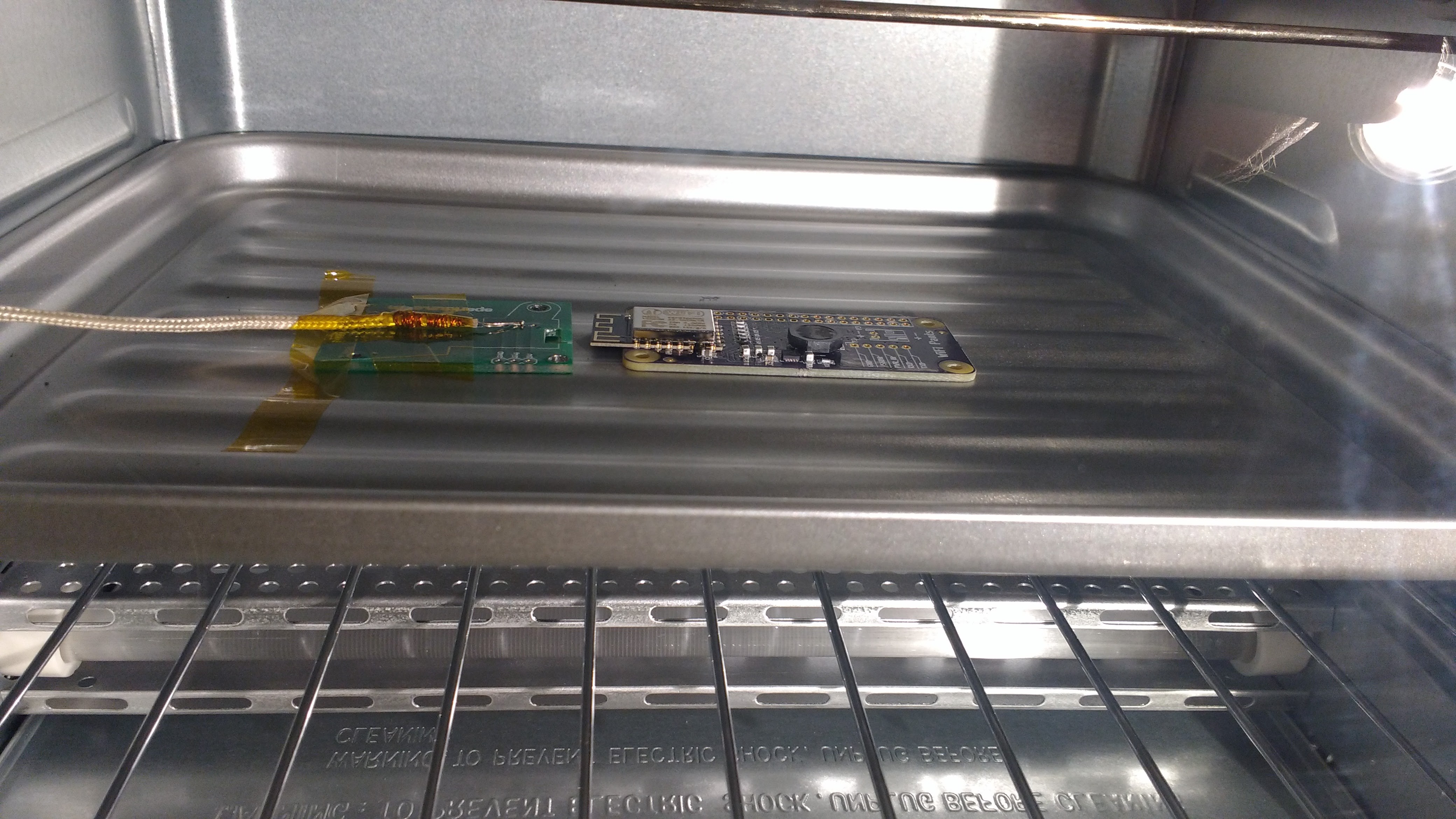
Boards came in today, so I had to get the reflow toaster out.
![]()
In the toaster during heat ramp up. I'm using only a thermocouple thermometer and a clock. No fancy profile controllers here.
![]()
So far, so good: the ESP-12F works well in 4-bit mode. The switcher tolerates feeding the Pi from the Pi microUSB input while not operating, and the shutdown input does what it's supposed to.
The reflow worked better than expected. I was concerned about the thermal vias under the switcher chip. They're necessary to transfer heat away from the chip and into the ground plane on the back side. But without special treatment during board manufacture (tenting, plugging, blind vias) they can wick the solder out the back and prevent the chip from making good thermal contact. OSHPark and other low cost board houses don't do any of those. So I increased the amount of paste on the pad to compensate. But that can have the opposite effect if the vias don't suck up enough, and the center pad will float the chip too high for the other contacts to solder to their pads. Fortunately none of that happened as far as I can tell without running it through an x-ray.
Most importantly, no smoke was emitted.
![]()
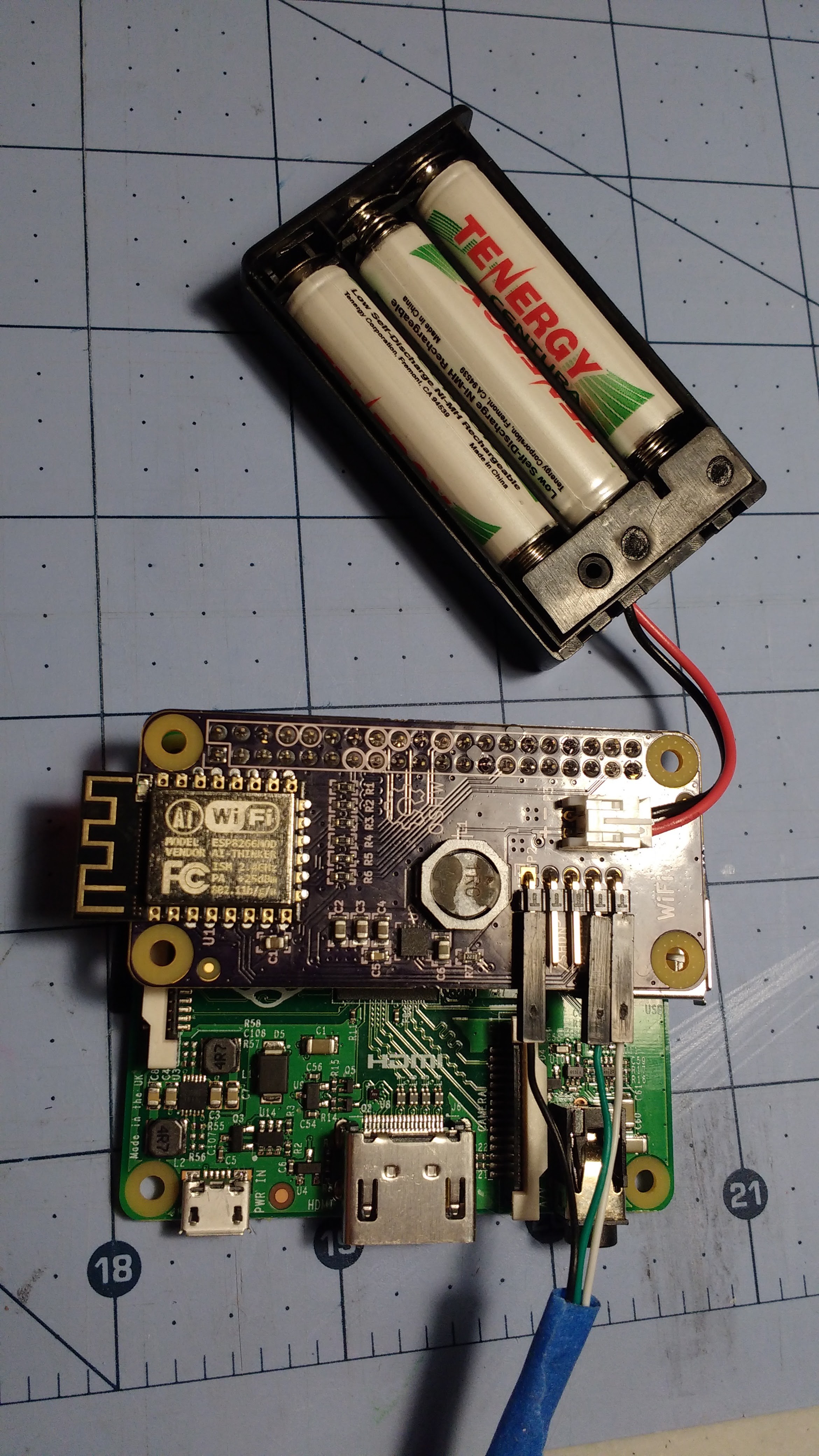
The switcher is happy to power a Pi A+ plus a bit of extra load on 3.6v worth of NiMH cells. Next step is load testing the switcher.
![]()
-
On SDIO and the Mysteries of the Universe
02/16/2016 at 18:28 • 5 commentsUp until now, I've been recommending that the flash be somehow disabled on ESP-12 modules. The flash and the SDIO bus share the same signals, and I was certain that the SPI flash chip on the module normally used for code storage would interfere with the SDIO bus.
It turns out that's not as likely to happen as I thought.
SPI flash chips keep all their pins as inputs unless they have been asked to respond with data. In single bit mode the MISO signal carries data from the flash to the host, and is the only one that can become an active output. For this to happen, one of a handful of commands with read responses have to be sent to the flash first. Meanwhile, the chip select signal (/CS) must be held active-low or the transaction is aborted. Data is sent to and from the flash in groups of 8 bits, with each bit being valid on the edge of the clock (CLK) signal. So for the SPI flash to do anything that could stomp on the SDIO bus, /CS must go low and stay low for 8 CLK edges while a valid command with a read response must appear on the MOSI pin.
The SDIO bus operates in a fundamentally different way, with the only commonality being the clock shared on the same pin (SD_CLK / SCK). Commands and response codes on SDIO are communicated through a dedicated bidirectional line called SD_CMD. The data payload sent to and from the SDIO device come over the bidirectional data bus on the remaining pins (SD_D0 to SD_D3). A typical SDIO register read starts with the host sending a command over SD_CMD requesting some number of bytes and a starting address. The device responds over SD_CMD acknowledging the request at roughly the same time that the data for the read is sent out over SD_Dn. The device keeps sending data with each clock pulse until the request is fulfilled, then sends a CRC for the packet and a stop bit to complete the transaction.
Allowing command / response packets and data transfers to occur simultaneously improves the bus throughput for SDIO. But it presents a problem because SD_CMD and the SPI /CS are shared. In the idle state, SD_CMD is held high which keeps the SPI flash idle. But when SD_CMD is active, the SPI flash will read in whatever is on SD_D1. SD commands and responses are fairly short: 48 bits for all but the device ID command. For some packets it is possible for part of the payload to have 8 to 16 zeros, which would be enough to cause the SPI flash to become active if the right data were on the MOSI signal (SD_D1).
Fortunately the SPI flash commands are all non-zero and non-0xFF. So if the SDIO data bus was in the idle state while a string of 8 or more zeros went across SD_CMD, the SPI flash would clock in all 0xFFs since SD_D1 idles high. The concern is when this happens while the data bus is not idle. In that case, the data present at each clock cycle on SD_D1 is latched by the SPI flash. And if the data happened to contain one of the read response commands to the flash, then the flash might try to drive data out on MISO and corrupt SD_D0.
In 1-bit SDIO, this should never be a problem. SD_D1 in 1-bit mode is repurposed as an active-low interrupt signal and is not likely to transition fast enough to form any of the read commands. But this failure could potentially happen in 4-bit mode because SD_D1 may be involved in a data transfer while a packet is going across SD_CMD.
I know others have been sending the SPI flash powerdown command based on work done by @haddyhad. That got me thinking about the actual likelihood of problems from SPI flash interference.
I have run throughput tests on an ESP-12F (unmodified) in 4-bit mode for days and have not seen a failure. I'm not clear why I haven't seen bus corruption, but I suspect the ESP holds off on data from a read command until after the response is sent. When I get a chance I'll look with a logic analyzer.
edit:
Suspicion confirmed. I captured a bunch of transactions under heavy load and it looks like read data doesn't start until well after the response completes. I guess this isn't as efficient but with 72Mbps max there's plenty of room on a 50MHz 4-bit SDIO bus.
tl;dr:
ESP-12F should work fine in SDIO 1-bit and 4-bit modes without modification or putting the flash in HOLD mode.
-
Pants of the future
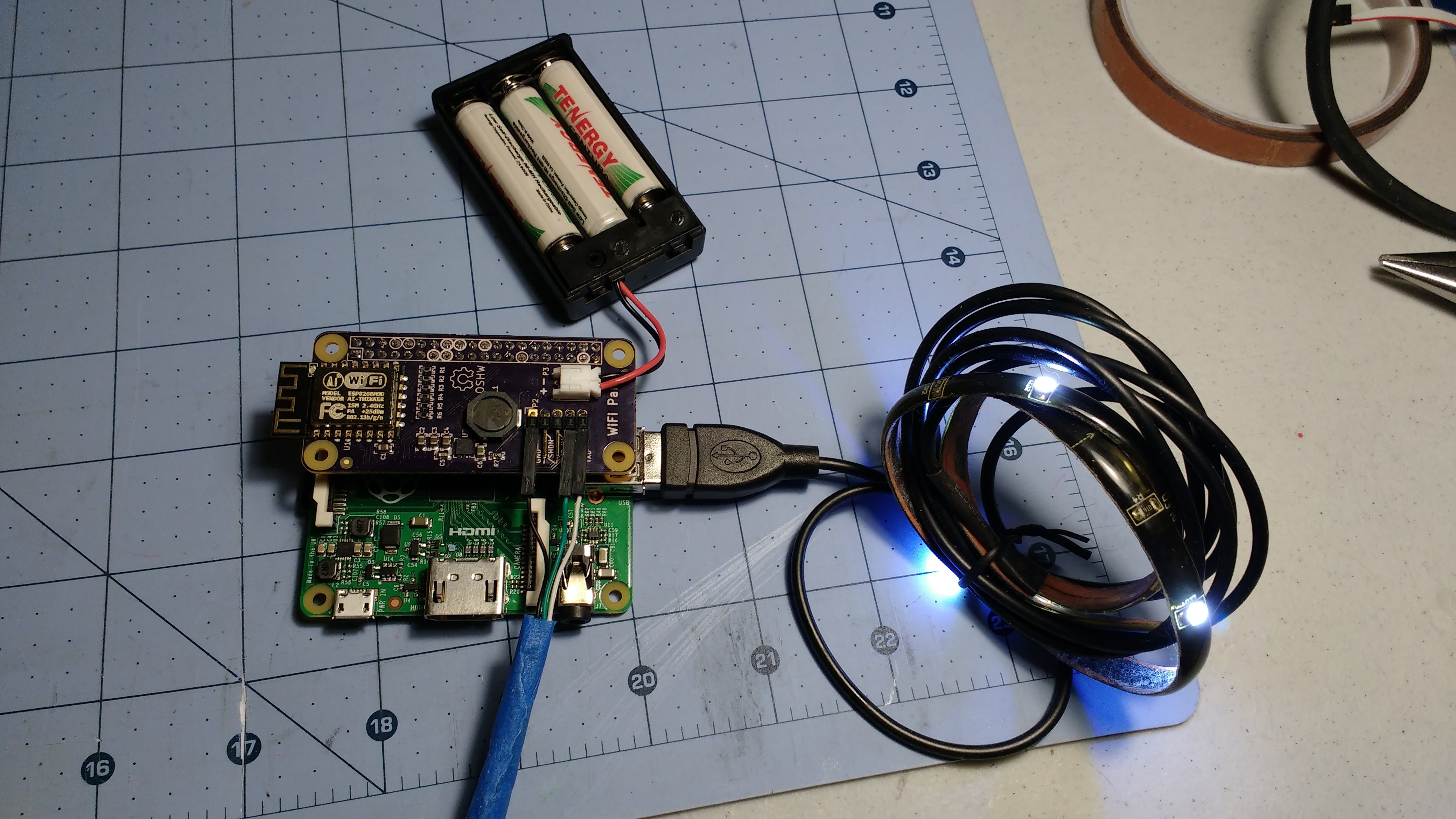
02/14/2016 at 09:01 • 6 comments![]()
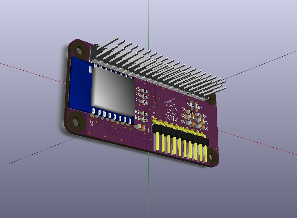
4-bit SDIO and 5V@2A boost converter for powering from batteries (1S LiPo, 1S LiFePO4, or 2AA). PCBs are on their way, but I still need to order the switcher parts and a stencil.
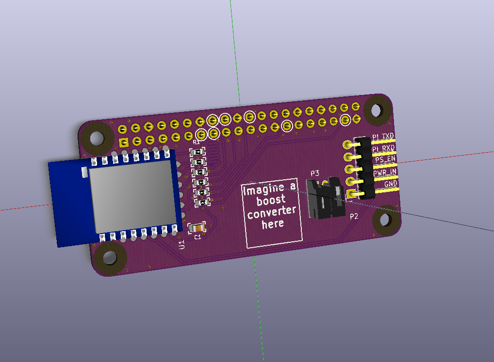
Bonus backside with alt connector stuffing options:
![]()
-
Big choices and small runs
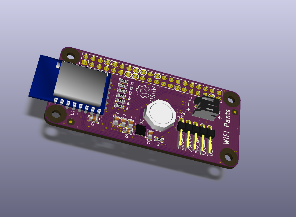
02/09/2016 at 19:36 • 11 comments![]()
This is a partial render of my next board spin. The big changes here are 4-bit SDIO (more about this later), removing the audio filters, and adding a 5V boost converter onboard.
I am working to add a boost converter to the Zero that should allow operation from 2.3V or so up to 5V. The converter should be good for about 1A above 3V, which is plenty for the Zero + ESP8266 + a typical USB device.Power supply is one area where all the Pis are weak, not just the Zero. I think it would benefit a lot of projects to run the Pi from 2AA batteries, or the existing power supply of a quadcopter or robot, or a standard LiPo pack. Having a simple boost converter makes all these options possible. I know the Zero (and A+) can potentially work at less than 5V, but there's some uncertainty as to how reliable it is or which USB peripherals will work reliably.
The 10 pin header on the bottom edge is gone, replaced by a 5 pin header on the right. This header has the same pinout for pins 1-5 as the old version, so an FTDI 6-pin cable can be used if the last pin is left hanging. This connector can be used to feed the boost converter's input and to control the boost converter enable signal (after cutting a jumper that keeps it always-on). The enable pin can be used with a switch or another micro to turn the Pi off and on remotely.
Inset from the edge is a 2-pin JST PH header, same as used by many battery packs and charge controllers. The distance from the edge is to give clearance to route wires out of the way of the USB and HDMI jacks. This header is not populated by default since it adds significant height to the board, but for batteries with high discharge capability it's safer to use a locking keyed connector like this.
As a compromise, the audio is gone. The power supply noise it picks up from the Pi's 3.3V is terrible, and the complexity to add a stable supply and buffering is too much work for something I feel will see much less use than the boost converter. I know some people are interested in adding back lost functionality of the Zero, but in my opinion a dedicated DAC HAT or one of the newer Pis are a better way to get audio out.
Meanwhile, I'm planning a small run of boards. These would be hand-assembled by me, so I'm thinking of only 20-30. I have some of the core parts on order, but I'll hold off on PCBs until I finish and test a few of this next-gen. And yes, these would be for sale.
-
Unchecked rage
02/02/2016 at 16:04 • 9 commentsI've thrown everything at the ESP-12F based board to get it to run at 62.5MHz. One of the HATs using my own ESP8266 layout works great with 1-bit SDIO at 62.5MHz. But this ESP-12F based proto doesn't.
At 41.66MHz, the SDIO host goes through the usual negotiation and then kicks the clock into drive. But at 62.5MHz, the SDIO host keeps retrying negotiation and the kernel log fills with "-110 timeout" errors.
But with the exact same settings, the other HAT works fine and comes up with a 62.5MHz clock.
Taking a suggestion from @David Lowe I got rid of the termination resistors. Til now I'd included them at the recommendation of the ESP8266 hardware guide and other SDIO designs I've seen. However the board works just as well without them running at 41.66MHz 1-bit SDIO. Actually the edges look better defined.
Good news though: @jacksonliam 's script to clear the flash's QE bit works properly after getting rid of the resistors.
I then threw a 33uF cap across the 3.3V rail, because that's what we do when we're at a loss. Of course it's not the supply, since SDIO negotiation doesn't present nearly as much dynamic load as WiFi operation. If the supply were an issue, I would have seen problems at the lower speed when transmitting.
Because it was late and I was frustrated, I pried off the lid to get at the flash. Some groundplane was torn up in the process, and I wasn't delicate with removing the flash. Miraculously it still works at the default bus speed, but at 62.5MHz the Pi still won't negotiate.
I have a couple of things left to try, but I'm about to cut my losses and forget about high speed for now.
Here's the carnage:
![]()
-
One leg at a time
02/01/2016 at 15:57 • 0 commentsI wasted most of my weekend free time on the audio out. The audio works using the userland procedure from Adafruit. I then tried and failed over the course of a few hours to do the same using devicetree overlays, but can't seem to get the same behavior overlaying the pin-function. I'll have to go digging through the driver.
Music sounds OK through my trusty old Altoids tin headphone amp, but there's a ton of noise floor coinciding with CPU load. It reminds me of my first PC sound card that telegraphed HDD and CPU activity through chirps and squeaks. Of course this is expected since the PWM audio power supply is the 3.3V IO rail on the Broadcom CPU. The A+ / B+ / 2 digitally buffer the PWM signals with a dedicated power supply, but adding that to this board is overkill I think.
I also tried out 62MHz mode, which the WiFi Pants board and one of my custom HAT boards didn't like. I did get it working with one of my other HATs, which was rigged for 1-bit mode and used a smaller series termination. I deviated from the schematic and used 150 ohms on the first Pants board to see if I could simplify the BOM, but that was probably a bad choice. I didn't have time to scope it, but given my previous testing I would expect to see some sad excuses for digital pulses.
As for the next rev, it took until now for me to realize that the serial / power / audio header blocks both USB connectors! With FTDI continuing to punish consumers maybe a different location and pinout is in order...
-
First Pants
01/30/2016 at 06:27 • 12 commentsThe boards for the WiFi Pants came in the other day, and I hastily soldered one together. Due to my ineptitude in KiCad and PCB design in general, I spent most of last night debugging the board. Long story short: made solder mask clearance too wide, OSHPark left a slight registration error in the mask, bridges between pads and the ground plane happened, ended up frying a USB hub.
I got it working, but didn't have time to do much more than bandwidth testing. ~24Mbits up, ~30Mbits down to the reference router. I used @jacksonliam's script to take the ESP's flash out of quad mode, with some issues on the readback (more sometime later). Haven't touched audio yet. It'll probably be Monday night before I have a chance to get back to this.
In the meantime, enjoy some pictures:
![]()
I proto'd this with the header backwards, since I have only one Pi Zero and don't want to solder the stacking pins through on it yet. Extras are hard to come by.
![]()
How a Zero looks with Pants.
![]()
Pretend the header isn't there.
![]()
-
Hide your Pi's shame
01/18/2016 at 18:36 • 21 commentsThe RPF cut corners on the Pi Zero to get down to $5. One omission in particular leads to another opportunity for expansion. By leaving the HAT header unpopulated there is no longer the restriction of stacking HATs on only one side of the board.
I present to you: PANTS
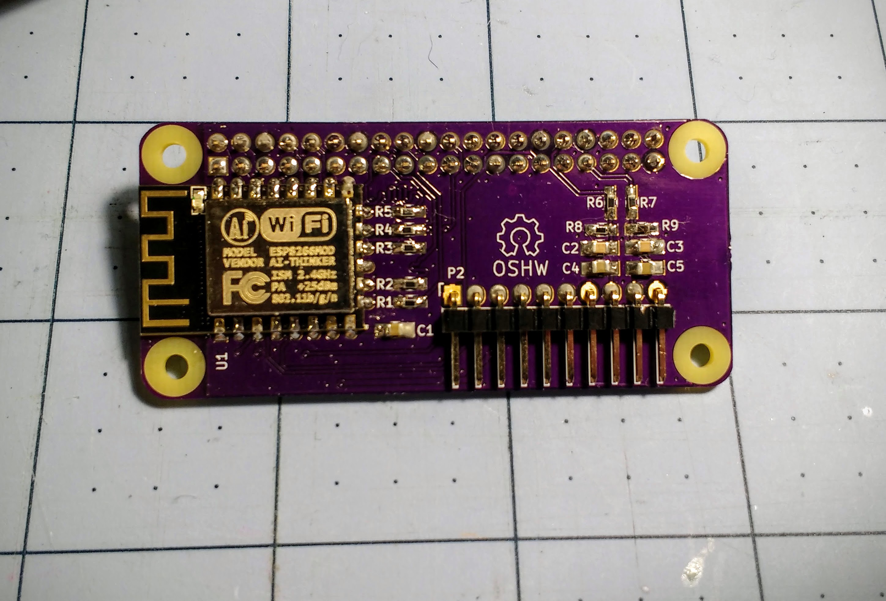
![]() A Pi Zero gets stacked and soldered on top. The header pins are extended so HATs can be stacked on top of the Pi.
A Pi Zero gets stacked and soldered on top. The header pins are extended so HATs can be stacked on top of the Pi.There's also a logo. I am not proud of this.
![]()
These pants use an ESP-12E/F module to avoid dealing with the FCC based on what I was working on in the last post. For a USAnian the ESP-12F isn't much more expensive than the ESP8266 chip plus the discretes to go around it, and much less after adding in NRE for certifications on a low volume specialty product. This does mean a downgrade to 1-bit SDIO, but in practice it should be speedy enough for the aging BCM2835.
In all the extra space I put down a 10-pin header for an FTDI 6-pin USB-to-serial cable (old Arduino style), +5V in, and audio out via the PWM GPIO hack. I went with the simple low pass + DC blocker filter used on the original Pi rather than the fancier buffered one on B+ and later to keep it cheap. If you want quality, get a USB DAC or use one of the existing I2S DAC HATs.
The 5V input is disabled by default, but when enabled by a solder jumper can power the Pi from the 5V USB on most FTDI 6 pin cables.
I also have cut-and-jumper pads to switch the CHIP_EN GPIO from GPIO5 to GPIO27. GPIO27 is an alt for the SD_D3 SDIO signal that's unused in 1-bit SDIO mode, and I think can be remapped with a devicetree overlay as a normal GPIO. This would free GPIO5 for other applications while using up a GPIO that would be taken up by SDIO anyway.
New Github repo to the left.
In other news, I did get the v0.2 of my HAT design back from OSHPark. The boards look good, but since I think the module design is more practical I'm in no rush to build one up.
 ajlitt



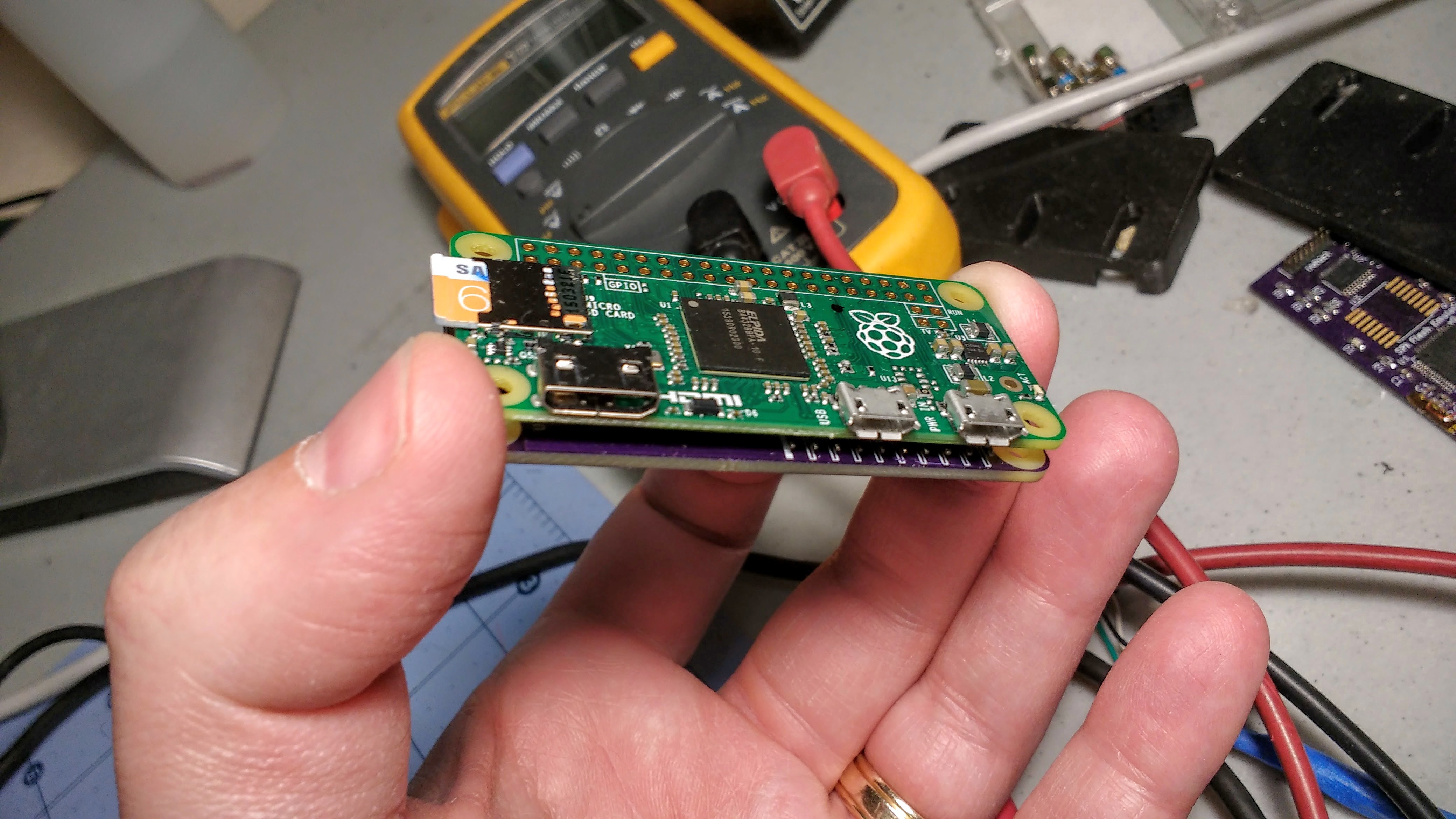
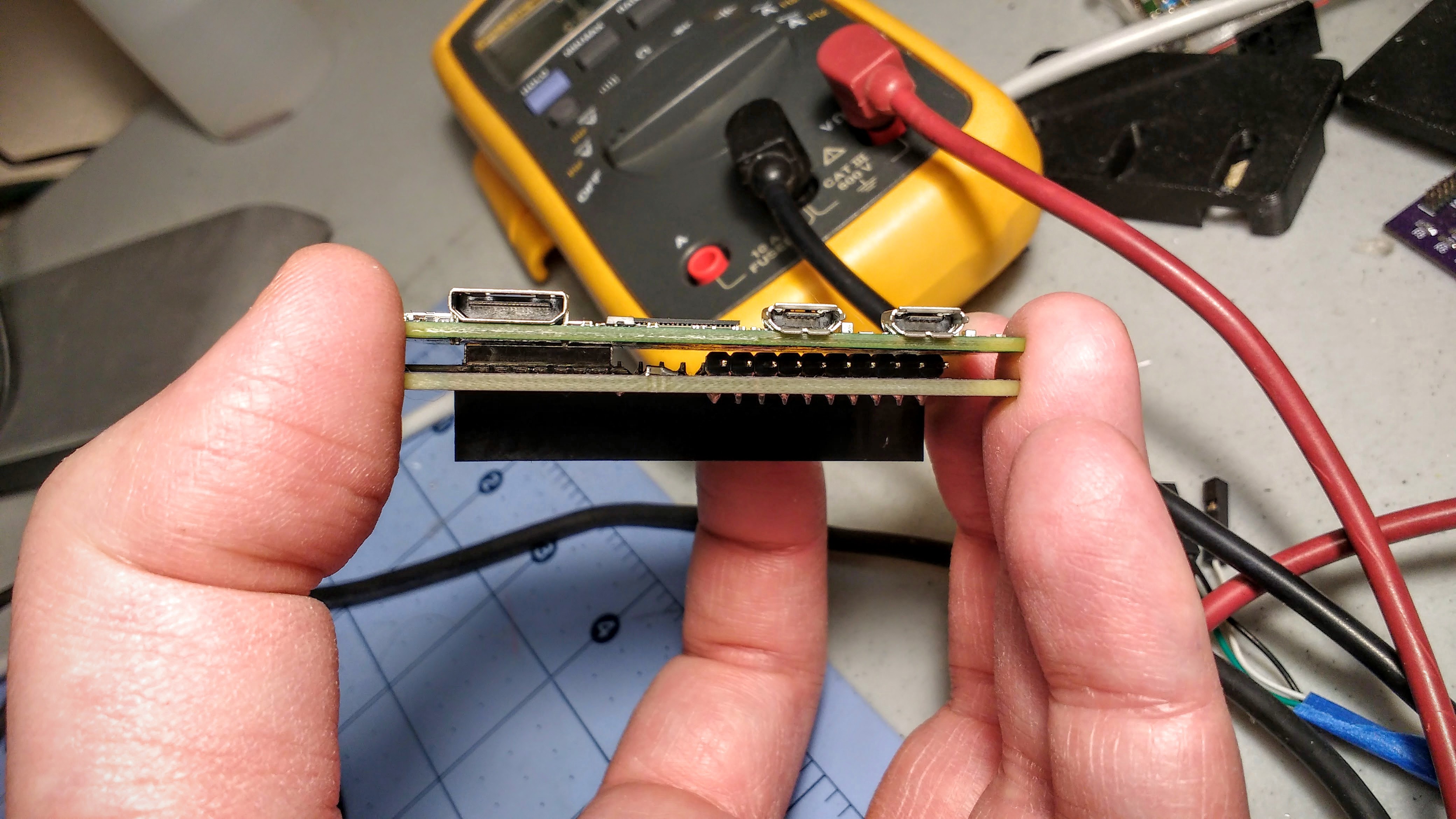

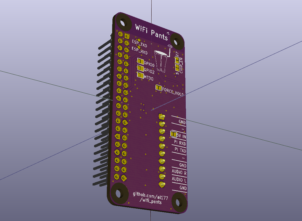 A Pi Zero gets stacked and soldered on top. The header pins are extended so HATs can be stacked on top of the Pi.