The last time I wrote about the decoders I was short on explanations. I had just built the first one of four. Now several months and a lot of redesigns later I am ready to give a longer explanation.
Originally I intended to build four separate decoders, each one driving a single seven segment display. However I was running out of space so I had to combine the decoders together in order to fit some extra relays responsible for carry and reset of the flipflop's.
Functionally there are the following separate circuits:
- Single-minutes decoder, connected to flipflop's 1A - 1E
- Tens-minutes decoder, connected to flipflop's 2A - 2C
- Single-hours decoder, connected to flipflops's 3A - 3E
- Tens-hours decoder, connected to flipflop's 4A - 4B
- Carry single-minutes to tens-minutes
- Carry single-hours to tens-hours
- Reset hours when '24' hours state reached
These circuits are now combined into two decoder boards:
Upper decoder:
- Single-minutes
- Tens-hours
- Reset hours
Lower decoder:
- Tens-minutes
- Single-hours
- Carry minutes
- Carry hours
Because I was running out of space, I had to move the functional blocks around a bit so that in the end each decoder board contains exactly ten relays.
Decoding the digits
The table below shows the decoding of the four displays.
DECODING LOGIC
! is NOT
& is AND
i.e. !A & E is (NOT A) AND E


Single-minutes

1A  1B  1C  1D  1E  |  Num  Logic
--------------------+--------------
0   0   0   0   0   |  0    !A & !E
1   0   0   0   0   |  1    A & !B
1   1   0   0   0   |  2    B & !C
1   1   1   0   0   |  3    C & !D
1   1   1   1   0   |  4    D & !E
1   1   1   1   1   |  5    A & E
0   1   1   1   1   |  6    !A & B
0   0   1   1   1   |  7    !B & C
0   0   0   1   1   |  8    !C & D
0   0   0   0   1   |  9    !D & E


Tens-minutes

2A  2B  2C  |  Num  Logic------------+--------------
0   0   0   |  0    !A & !C
1   0   0   |  1    A & !B
1   1   0   |  2    B & !C
1   1   1   |  3    A & C
0   1   1   |  4    !A & B
0   0   1   |  5    !B & C


Single-hours

3A  3B  3C  3D  3E  |  Num  Logic
--------------------+--------------
0   0   0   0   0   |  0    !A & !E
1   0   0   0   0   |  1    A & !B
1   1   0   0   0   |  2    B & !C
1   1   1   0   0   |  3    C & !D
1   1   1   1   0   |  4    D & !E
1   1   1   1   1   |  5    A & E
0   1   1   1   1   |  6    !A & B
0   0   1   1   1   |  7    !B & C
0   0   0   1   1   |  8    !C & D
0   0   0   0   1   |  9    !D & E


Tens-hours

4A  4B  |  Num  Logic
--------+---------------
0   0   |  0    !A & !B
1   0   |  1    A & !B
1   1   |  2    A & B
0   1   |  X    -
Let's have a look at the first table, which shows the decoding of the rightmost digit, the single-minute digit. This digit is controlled by the first five flipflop's, numbered 1A through 1E. The first five colums represent the output state of these flipflop's. Notice the progression typical of a johnson counter, totally different from a binary counter. Next you see the number that this state represents and the final column shows what logic is needed to decode a number. For example, to decode the number '5' , flipflop A and flipflop E have to be both on.
Implementing the logic
The logic to decode the state of the flipflop's is all implemented, again, in relays. As you can see, every 'statement' consists of two inputs that are logically AND-ed together. To get an AND function in relays, you simply chain the outputs of two relays together. So to get A & B, you chain the normally open outputs of two relays in series. The current flows through the contacts only when both relay A and relay B are on. By using a combination of the normally open and the normally closed contacts you can implement the NOT function as well.
A very convenient property is that the combinations form pairs that are opposites of each other. For instance A & !B and !A & B are opposites. So are B & !C and !B & C. In fact, the ten combinations form five pairs. This property allows you to save relays. To implement the logic for a pair, only two relay contacts are needed, one from each relay. Because the displays are made of LED's, current can only flow through them in one direction. I am making use of this by wiring the LED's together in the opposite direction. See the little schematic below.
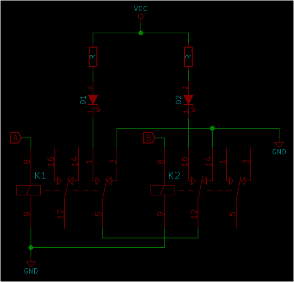
Two relays, K1 and K2 with their inputs A and B. The outputs are LED's D1 and D2. The outputs of the relays are wired in series to produce the AND function. if both relays are off (!A & !B) the grounds are wired together and nothing happens. If both relays are on (A & B) the LED's are wired together in the wrong direction, no current can flow and thus nothing happens. Only if one of the two relays is on, and the other is off can the current flow to ground through one of the diodes. The behaviour of D1 can therefore be expressed as A & !B and the behaviour of D2 as !A & B.
This example shows just two states to decode, but decoding the other states works the same way. Each relay has two sets of contacts. For decoding one pair, only one set of contacts is used. Each relay is involved in the decoding of two pairs. The second set of contacts is used for decoding the other pair.
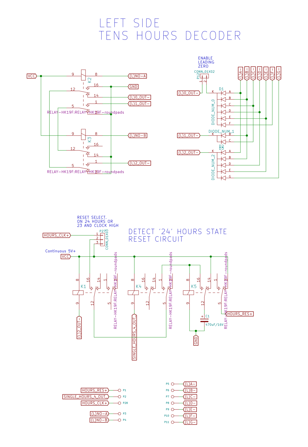
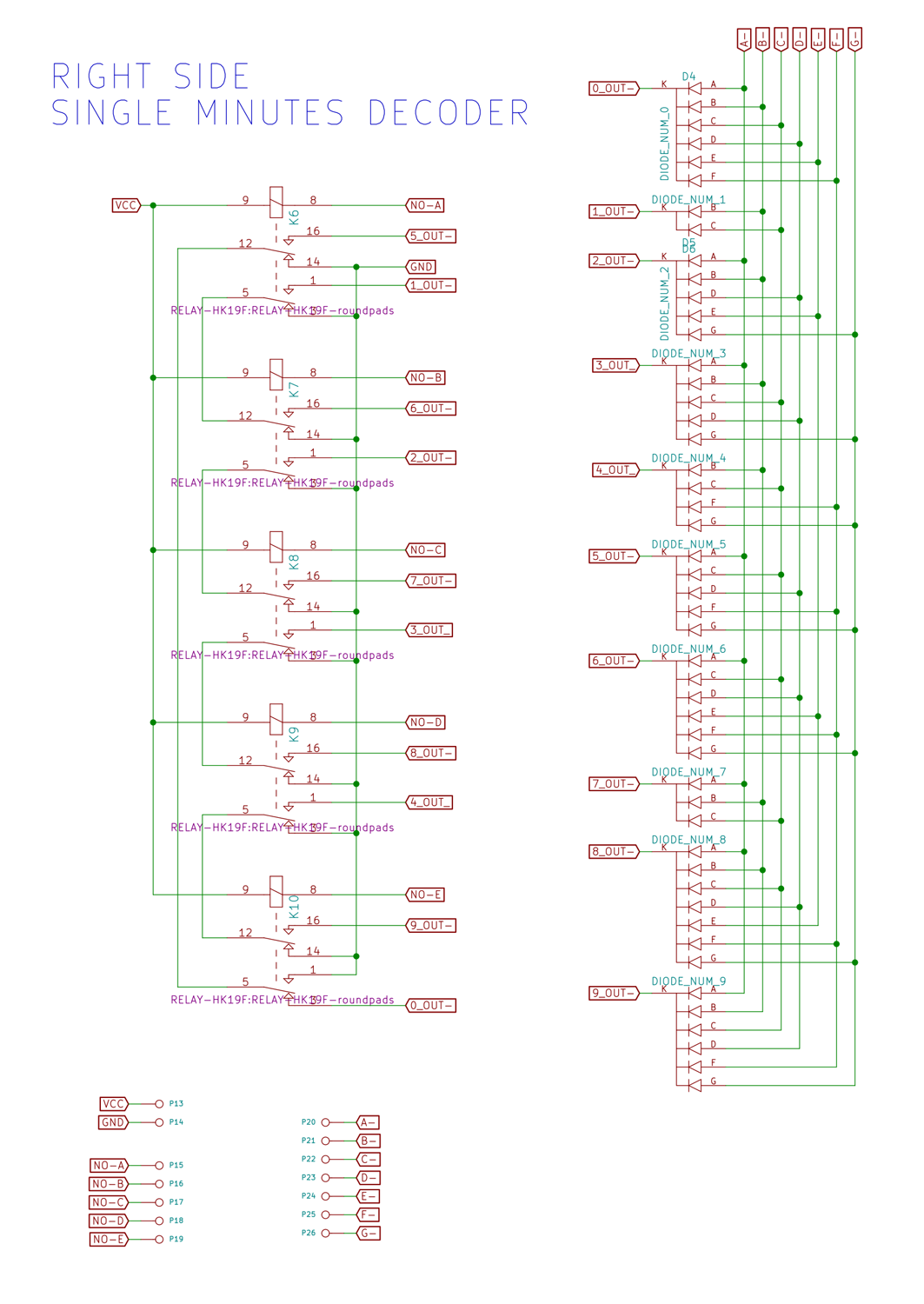
Look at the relay connected to the output of flipflop 1A. This relay is involved in the decoding of four pairs: !A & !E, A & !B, A & E, !A & B. This is why it's possible to decode ten numbers with just five relays. Below is the full schematic of the upper decoder.
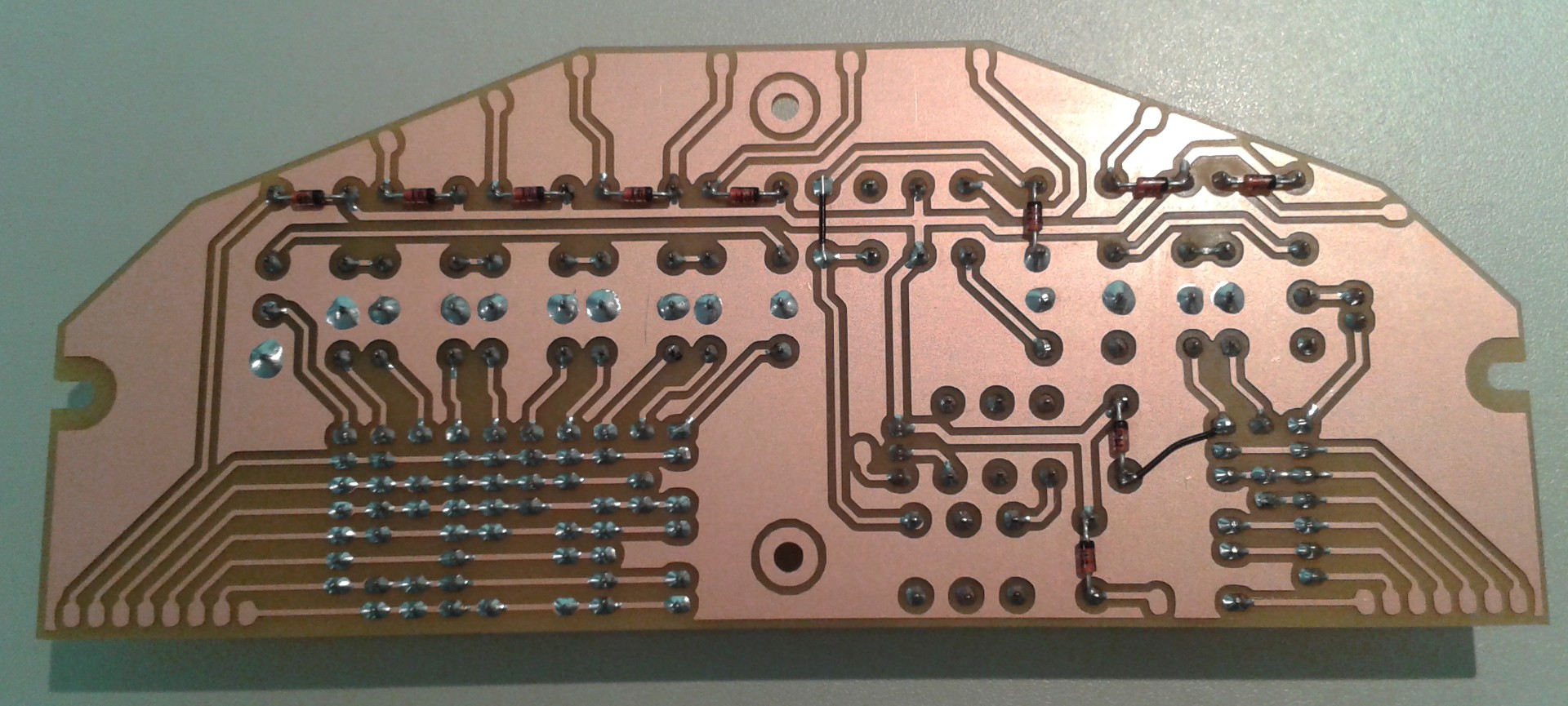
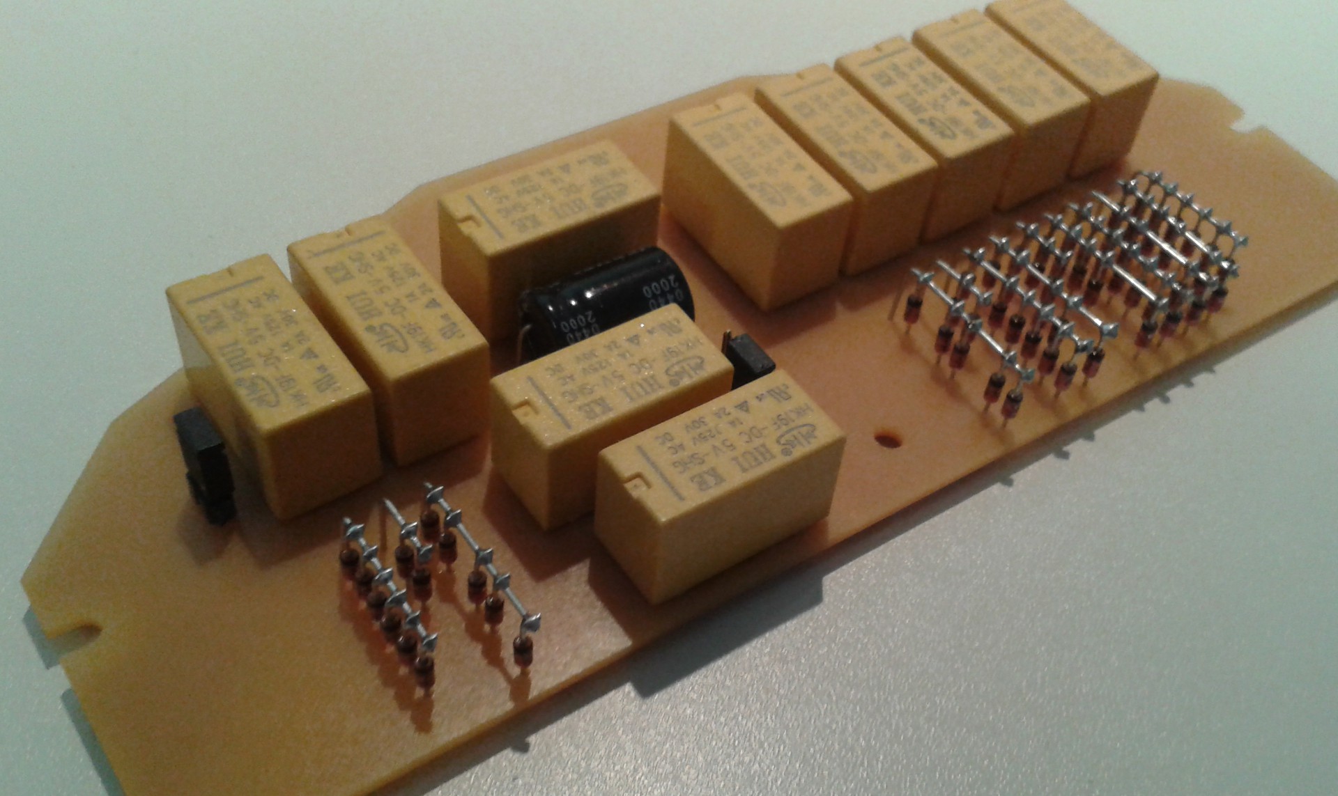
And here's the final PCB of the upper decoder after milling and soldering
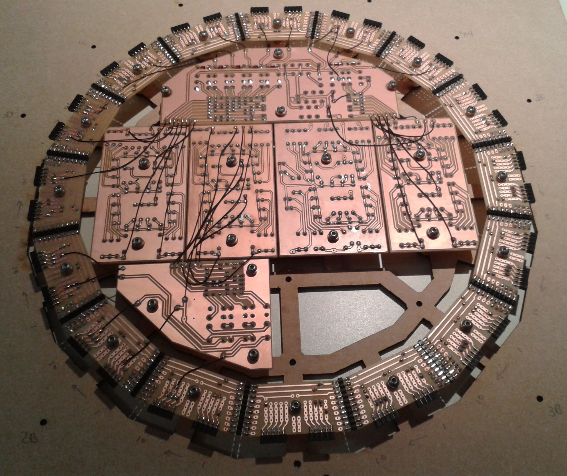
And finally here's the back of the clock while wiring the new decoder into place. For this procedure I had to transfer all the boards to a second assembly frame (lasercut from 3mm MDF) so I could flip it over without moving the boards around. The flipflop boards are removed to reduce stress on the boards and reduce weight while working on it.
 Dave Gönner
Discussions
Become a Hackaday.io Member
Create an account to leave a comment. Already have an account? Log In.
Is it me, or are the schematics almost illegible because they're dark red and blue on a black background? I tried Firefox and IE...
Neat project... I've never done relay logic, interesting to see an actual project done with it.
Are you sure? yes | no
No you are right, and I fixed that for you.
Relay logic is amazing, though impractical. They make more noise than I would like, but it makes one hell of a display piece!
Are you sure? yes | no
Congrats on the progress !
I am doing something with a similar idea at https://hackaday.io/project/9376/log/38030-my-first-discrete-5-stages-johnson-counter
Are you sure? yes | no
Thank you! The completion of the electronics is getting nearer. I am following your build with interest as well, I especially like your very complete documentation. I find it quite difficult to write good docs. Do people actually understand what I'm writing? I have no idea ;-) Have to keep trying to do better.
Are you sure? yes | no
I sometimes wonder the same things about my own writings ;-)
Anyway you give clues, hints and tips so if I don't immediately understand your system, at least I can imagine how I would do it myself. Unfortunately this might have stimulated the creation of one project or two :-P
Are you sure? yes | no