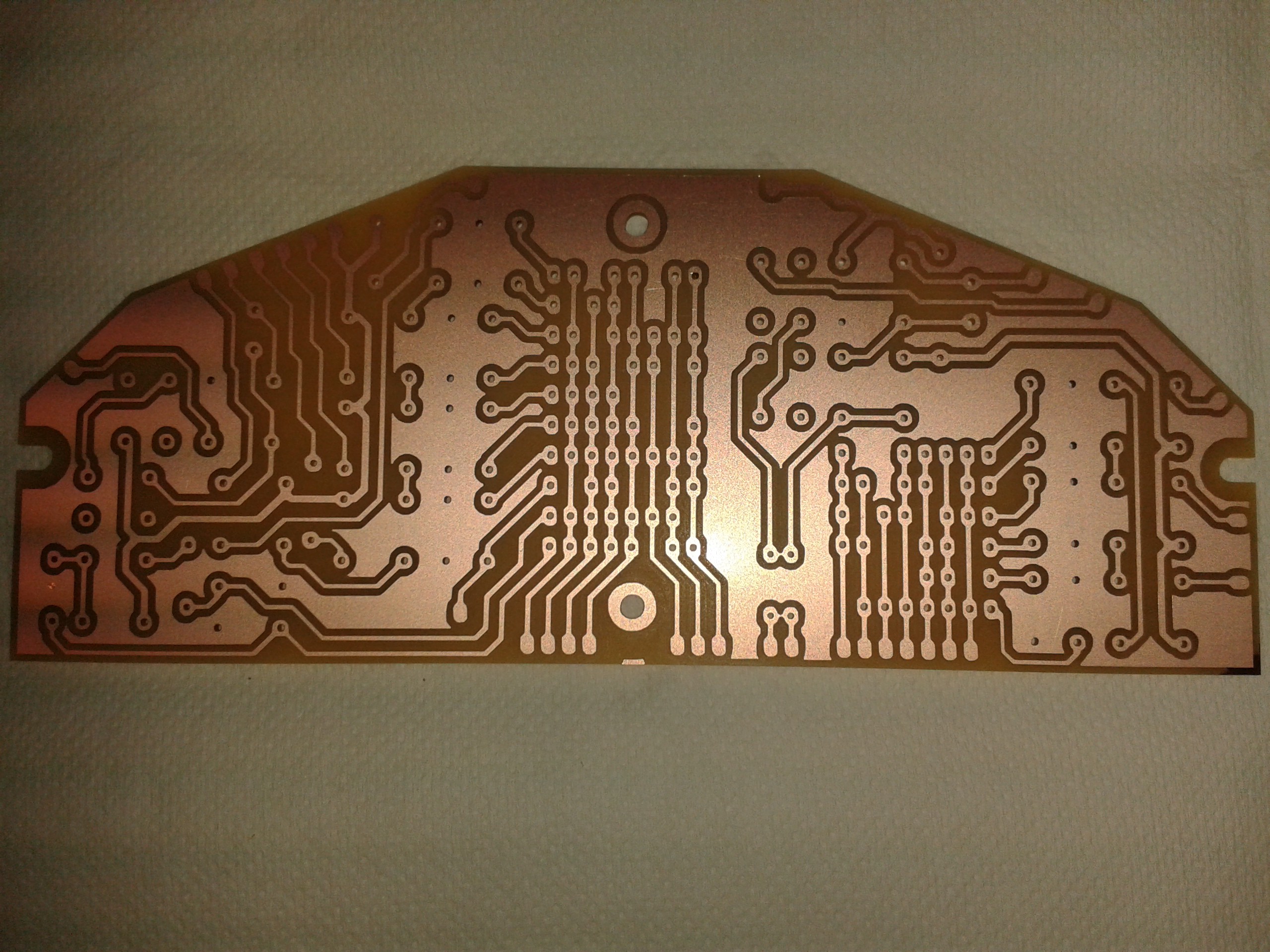
The last PCB, fresh off the mill. This is the lower decoder board. It replaces the two separate decoders I made earlier, because I had to add extra circuitry for the carry logic.

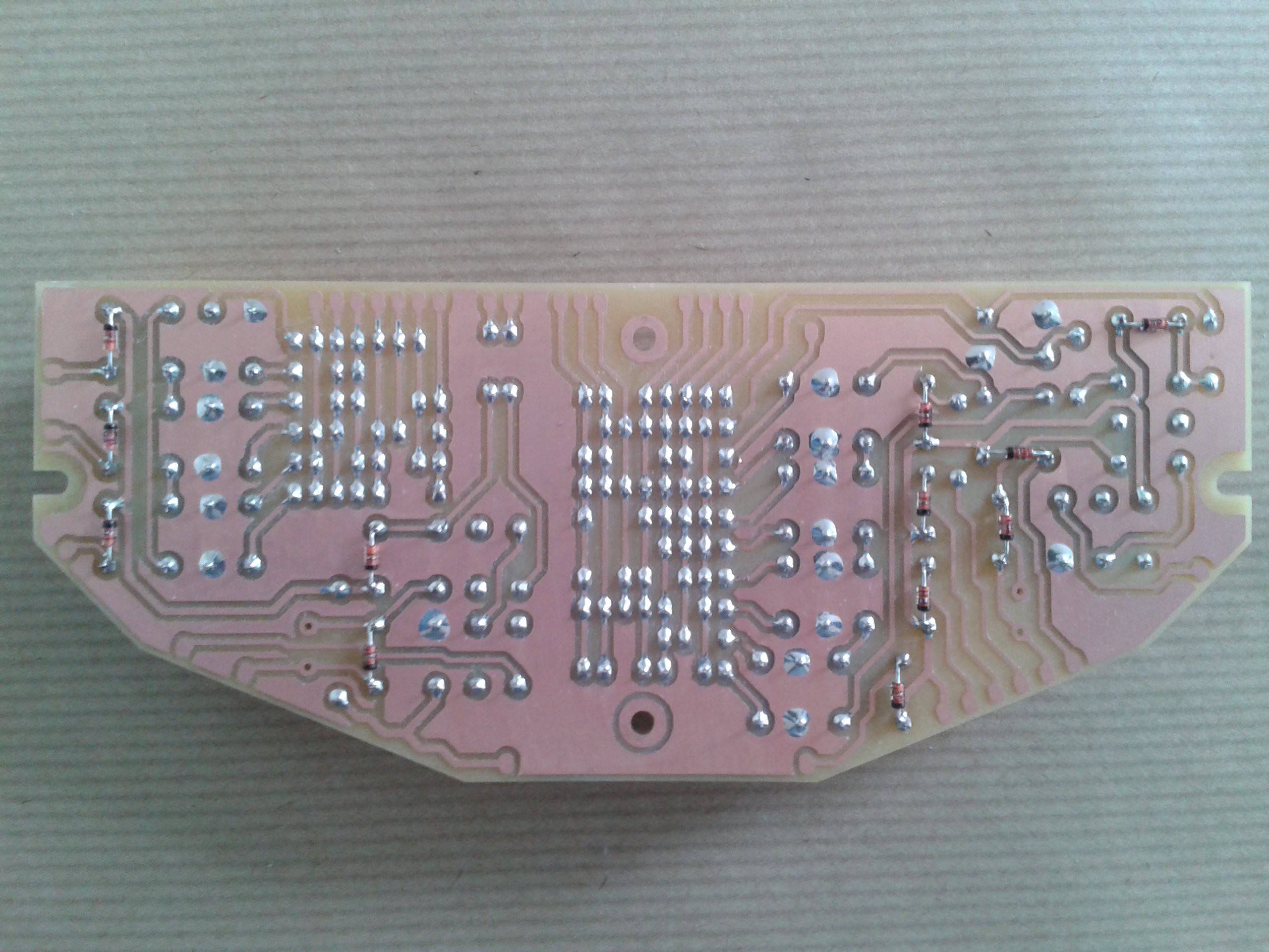
Here it is after soldering.

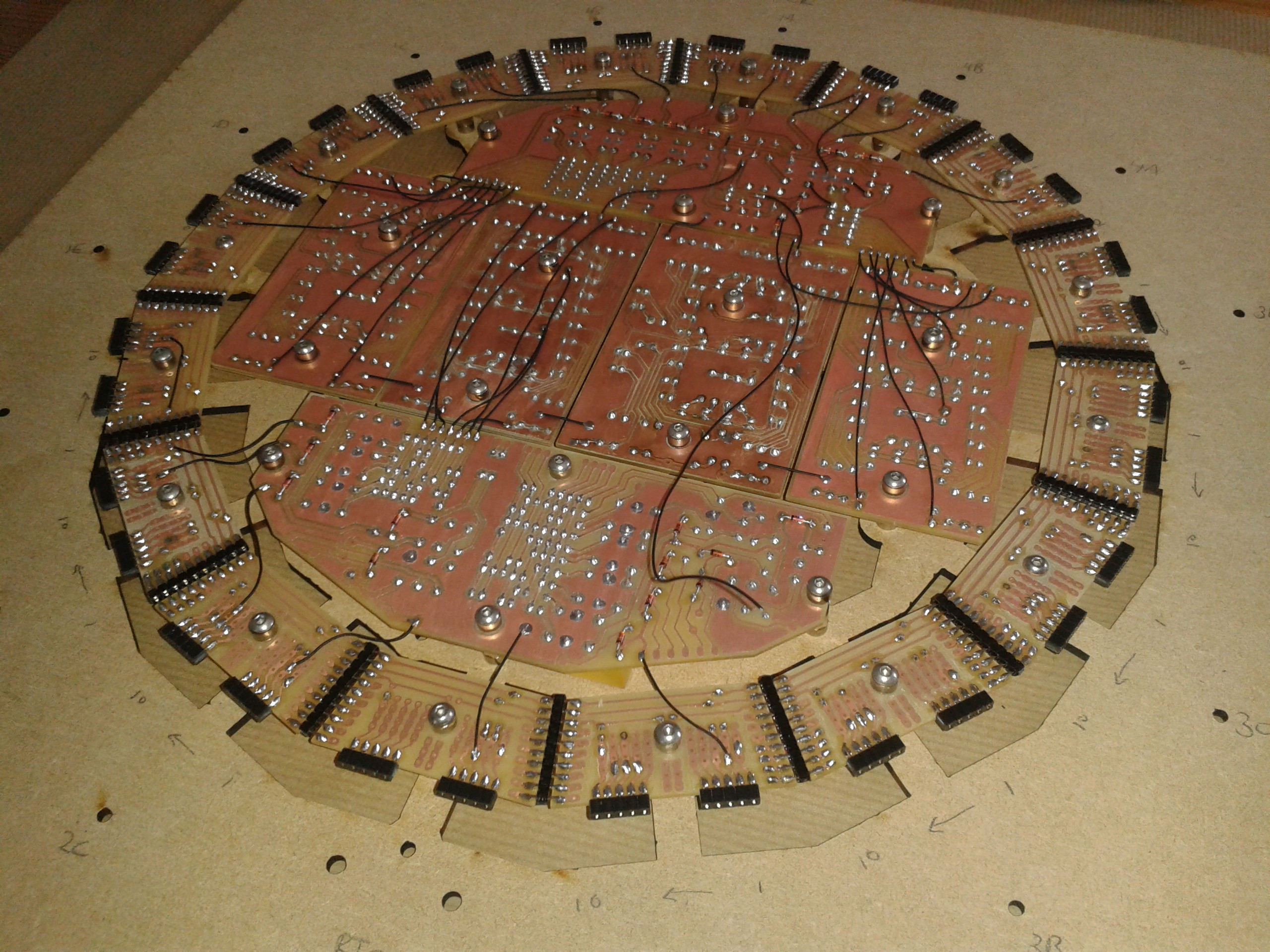
Those diodes are a real challenge to do consistently. Here is a view from the back of the clock. I had to transfer all the PCBs to a new carrier board (the piece of MDF), without disturbing the delicate wiring. I removed the flip-flop boards to make it easier to handle. You can see I just started wiring in the new lower decoder board.

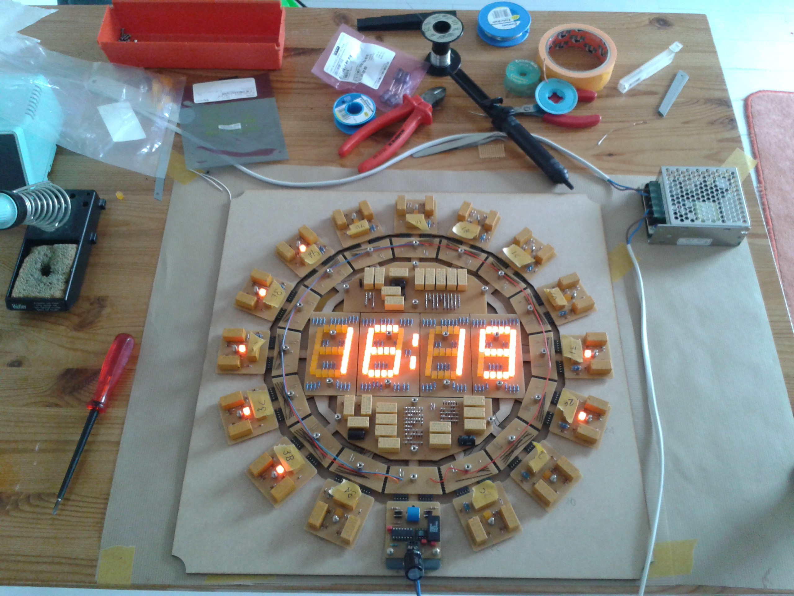
And there it is, in all it's warm glowing glory. Completely functional, although the wiring needs some work. This is a major milestone for me. The first time all the components are in place and everything seems to be working. Now I can start designing the plexiglass frame that it will be mounted in.

That's it for now. Thanks for reading! Cheers.
 Dave Gönner
Discussions
Become a Hackaday.io Member
Create an account to leave a comment. Already have an account? Log In.
Nice looking clock!
Are you planning on making the design files available? Artwork, source code, etc.?
I would be interesting in making one of these.
Are you sure? yes | no
It sure is fantastic to look at, and to listen to. Nice to hear that you like it. The horrible camera doesn't do it justice in high-res ;-)
Are you sure? yes | no
https://cdn.hackaday.io/images/1277361542642581418.jpg
Are you sure? yes | no
I had to dig into the HTML to find the large-size picture of the whole clock, it's a crazy sight !
Great job !
Are you sure? yes | no
YAY !
Are you sure? yes | no