Close
0%
0%

Z80 overpowered computer

I am building a computer with a 4MHz Z80, 32KiB EEPROM, 32KiB RAM, IDE interface and UART.

Similar projects worth following
Super awesome z80 computer, fully upgradable and limitless. Also open source.

OK, so here are the system specs I will at least have in the end, and may get better over time.

RAM in minimal system32 KiB
maximum RAMNewer motherboard to support up to 96KiB
video resolutionVGA or lower
Disk space in minimal system64 KiB EEPROM
expansion slots0-8
Extra features
main system clock speed4 MHz
OS???

This is the third fourth attempt at getting this thing working, and it seems to be getting easier and cheaper over time. I think this time I'll get it right. Things on the board do quite a bit already, because there aren't really any errors in the PCB (I need a new motherboard...)

CPU clock speed auto adjust

The RAM I am using is BLAZING fast. Not very retro, but whatever. The EEPROM, however is very slow. 150ns. If the EEPROM is deselected, why not go at a faster speed? The CPU I have can handle 20Mhz. New logic in my motherboard (see logs) allows faster speeds, but the other devices can only handle a small boost.  I am going to cap the speed at 8MHz for now, assuming EEPROM is unused.

Motherboard

I like the concept of motherboards.  I'm just used to it from building computers.   I have ordered 5 motherboards from easyEDA.  RTC is supported, but I when I ordered the RTC chips they sent me the wrong chips!  I will work on other stuff for now.

mobo_0.1.sch

Newer motherboard, actually ordered

sch - 58.63 kB - 09/12/2017 at 04:33

Download

mobo_0.1.kicad_pcb

Newer motherboard, actually ordered

kicad_pcb - 917.19 kB - 09/12/2017 at 04:33

Download

mobo.kicad_pcb

first version of my flexATX motherboard featuring a Z80 processor as a PCB

kicad_pcb - 641.09 kB - 06/17/2017 at 21:08

Download

mobo.sch

first version of my flexATX motherboard featuring a Z80 processor schematic

sch - 54.35 kB - 06/17/2017 at 21:08

Download

mobo.pro

the KiCad Project

pro - 2.46 kB - 06/17/2017 at 21:08

Download

View all 6 files

  • 1 × Z80 CPU, min 4 MHz, preferably CMOS processor for the system made by zilog
  • 1 × 74HC42 Selects chips & boards, could be replaced by similar chips.
  • 1 × System Board Solder together on a protoboard
  • 5 × 1k resistor used for pull up and pull downs
  • 3 × 330 ohm resistor allows LEDs to run at 5 volts

View all 10 components

  • Almost standing on it's own

    Dylan Brophy04/06/2019 at 03:07 0 comments

    While away from HaD I added a keyboard and 64KiB of extra EEPROM.

    For a computer to be reasonably usable it needs a keyboard, monitor, and permanent storage.  I finally have all three!

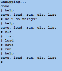
    I got that graphics card working from the previous log, and have given it it's own project #uPD7220 Graphics (and VGA hack).  For the keyboard and EEPROM, I figured out how to connect an ATMega328p to the Z80 and to the peripherals.  The ATMega's serial port is also accessible from the Z80's programs.  Now the computer can load programs from the EEPROM, and I can write to it via a serial port.  (Instead of pulling out the EEPROM, programming it, and plugging it back in)

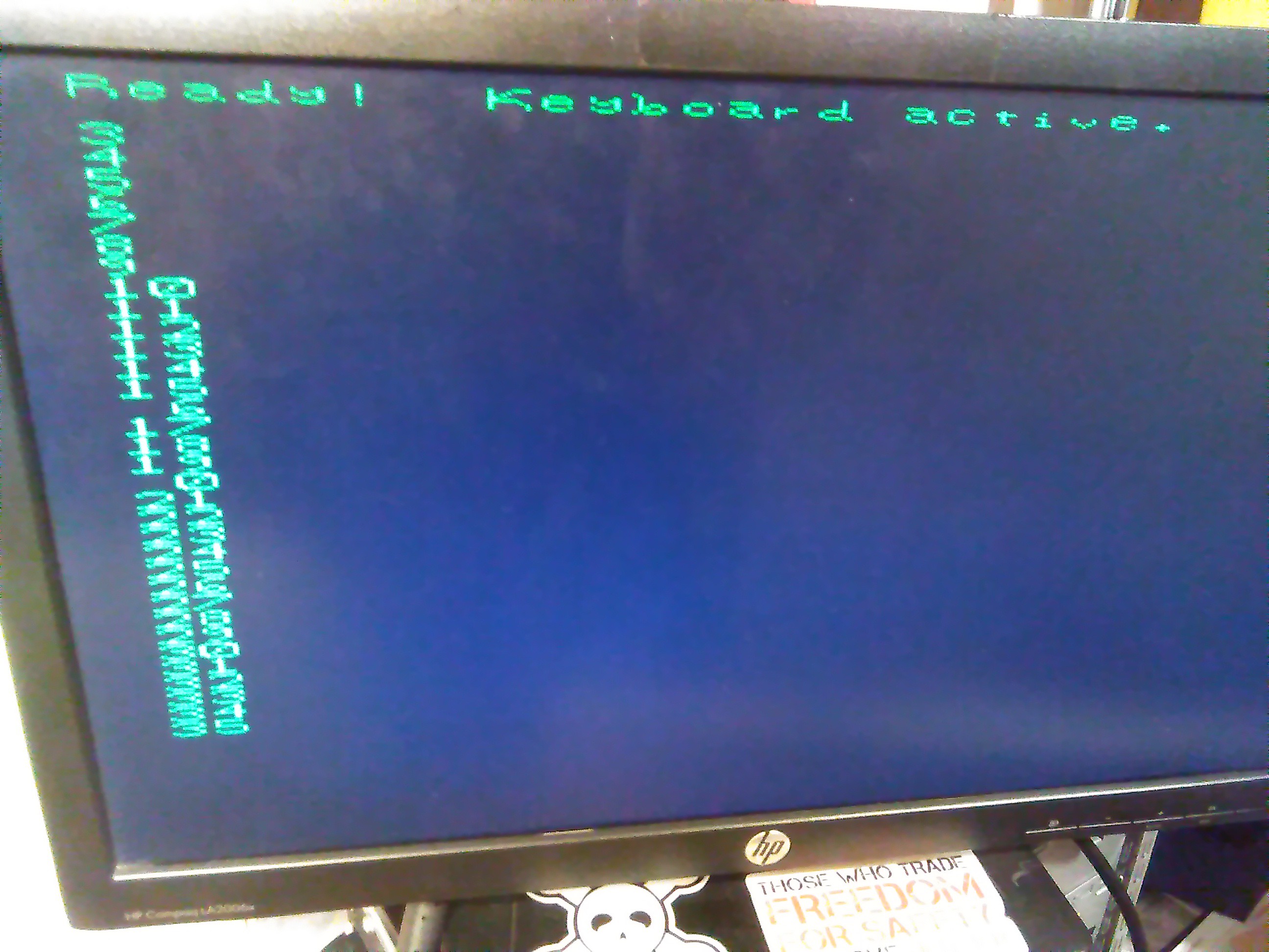
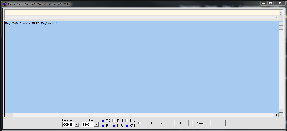
    Here is a program in EEPROM that reads keyboard presses and prints them on the screen:

    The font and character rendering isn't the best, but I don't want to be forced to use a modern computer and serial terminal every time I use my Z80 computer.  Besides, I will be able to render graphics as well.

    The computer's new boot sequence looks something like this:

    1. Initialize basic devices (not graphics cards or extra devices) and software
    2. Check to see if block device zero's first sector ends with "ye"
    3. If the first sector does end in "ye", then it is bootable.  Execute it.  Otherwise...
    4. Start the 'flash program'

    The flash program is like a monitor program except it is controlled by a python script.  It's just for writing memory, testing programs, and installing OSes for the first time.

    I designed the boot sequence like this because I am far too familiar with the x86 boot sequence, and because it allows me to easily modify the memory.  The parallel eeprom chip cannot be written by the Z80, so I have to remove it for programming.

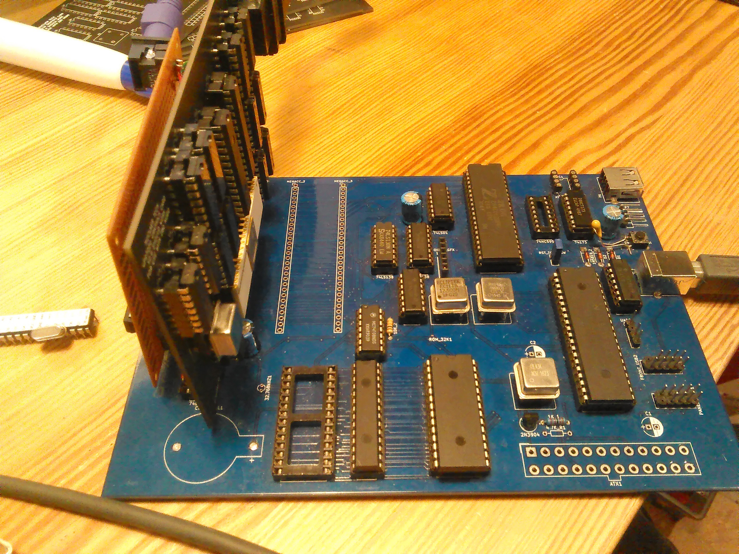
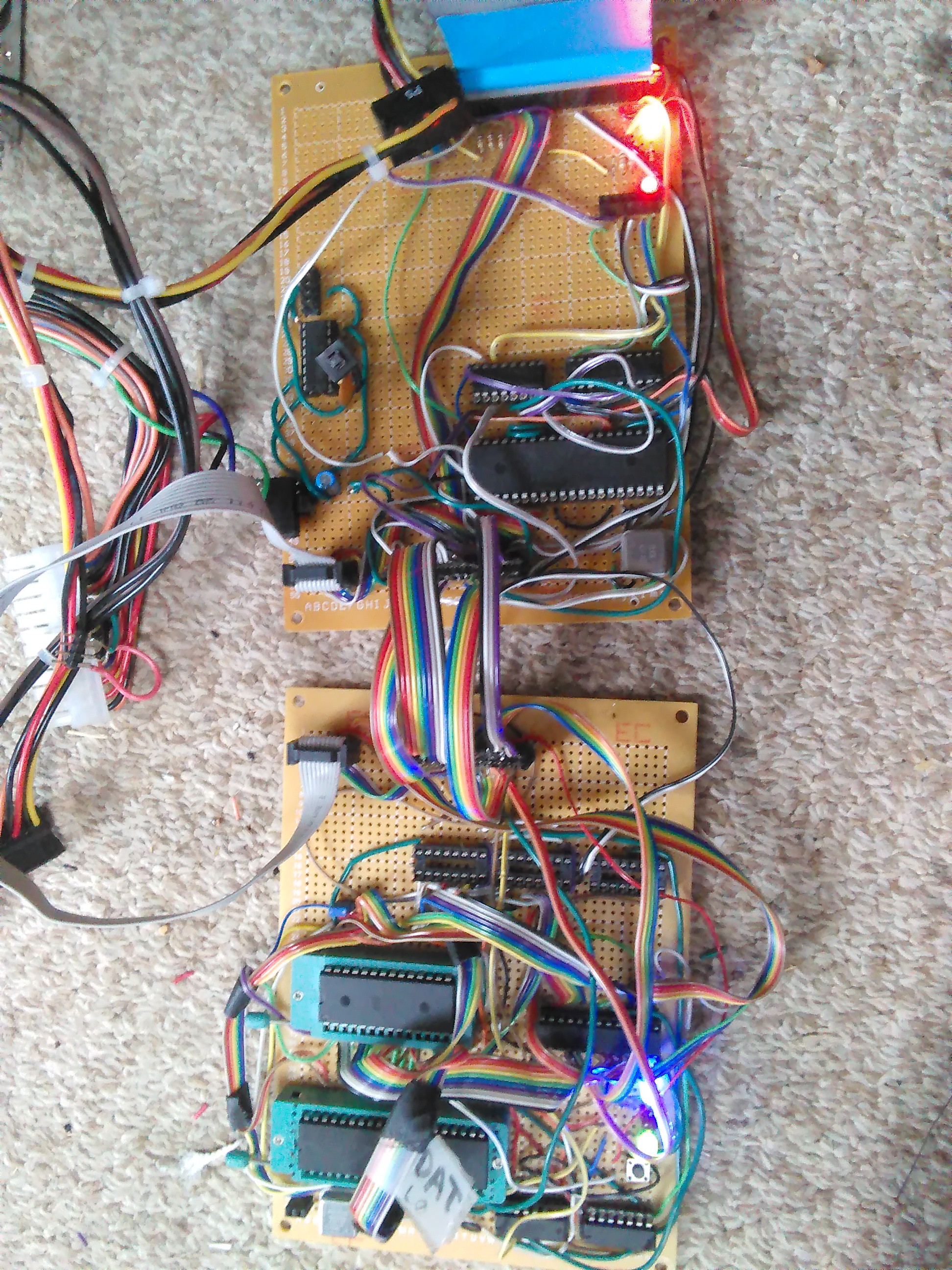
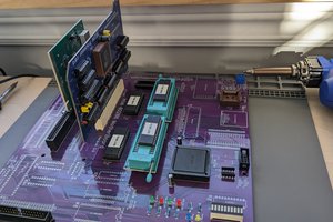
    Here is a picture of what the computer looks like now:

    The card on the left has the ATmega.  The other card is the graphics card from #uPD7220 Graphics (and VGA hack).

    I have different ideas about how the motherboard should be designed now too, so I would like to make a new one.  This one has a limited number of expansion slots, many unneeded or broken features, and *should* support banked memory expansions, but I want that feature to be built into the motherboard.

    Here is what I have done since last time:

    • Added keyboard
    • Working graphics card
    • Added EEPROM "disk"
    • added boot sequence and 'flash program'
    • Added a ROM font in the parallel EEPROM
    • Removed Herobrine

  • Work on a Better Graphics Card

    Dylan Brophy11/15/2017 at 17:01 1 comment

    I haven't yet gotten the CF card to work... but I had already been working on a graphics card using the UPD7220.  I got the boards and am working on drivers.

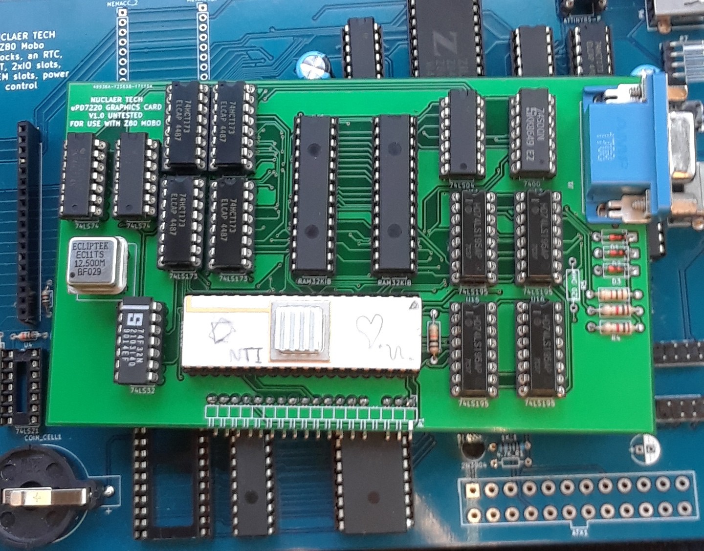
    here is the assembled board atop my motherboard:

    The card overclocks the upd7220 to 6.25Mhz and uses a 12.5mhz pixel clock. It has 64KB of RAM (more than the rest of the computer!) and can display 16 colors.

    The driver is giving me back some interesting information.  It consistently tells me that 4 commands are sent without overflowing the UPD's FIFO, that horizontal blanking is active, and that the FIFO is not full nor empty. The last is odd, the FIFO should be empty before the first command.

    The driver tries, as a test, to write and read memory at an address in VRAM.  The UPD7220 never sends data back, so I think there is a problem sending the commands to the UPD7220.  Interesting!

  • Reading sectors, FAT fs driver: error traceback

    Dylan Brophy10/08/2017 at 19:40 0 comments

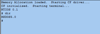
    The CF card I had been using was 512MiB, which I have learned is incompatible with my hardware setup... thus the errors.  After getting a 128 MiB CF card, I tried an IDE/CF driver for Z80 I had downloaded a while back.  I read the first sector and got the os name at offset 3, then sent it via serial:

    I used the 'dir' command because there is no fs yet, so we can't list files.  But as you can see, it clearly responds with 'MSDOS5.0', meaning reading sector zero actually worked.  Yay!  now lets make a FAT driver...

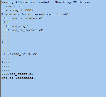
    First tests of this FAT driver made the computer simply stop, endlessly waiting for the drive to be ready.  I knew the drive had errored, but why?  What piece of code caused the error?  Time to make a stack tracer.

    I put strings before each function call which could lead to an error, then made a program trace any drive error. We can see that the problematic code is at 0x489, where the filesystem is loaded. More specifically, where the root directory is loaded into memory.

    I got the drive error code: 0x10, like last time, that the sector wasn't found.  So I guess I tried to access a sector that isn't on the card...

    That is the next thing to fix.

  • Making friends with some compact flash (almost)

    Dylan Brophy10/06/2017 at 04:35 0 comments

    Many of my tests yesterday gave me zeros on the status register.  I played with it for a while with no avail, but I decided to treat the motherboard as if the expansion ports support hot plugging (they shouldn't).  To my surprise not only did the computer not crash, but the CF card actually started working!  Almost.

        The card gave me an error code: 0x10, aka Sector ID not found.  As of yet I haven't found out exactly where this error comes from, but I think it means that the sector doesn't exist.  I set the sector to zero, but I am currently using a crappy test driver that is probably the issue.  But, I'm talking to it!

    You will notice that usually the number (the status, in hex) is 51, bit one being set meaning an error occurred.  when I remove the CF card it becomes 50 once, indicating no error.  This means my driver code is broken.

    I am going to play with someone else's driver, will post another log.

  • Late Log, but motherboards received!

    Dylan Brophy10/01/2017 at 00:30 0 comments

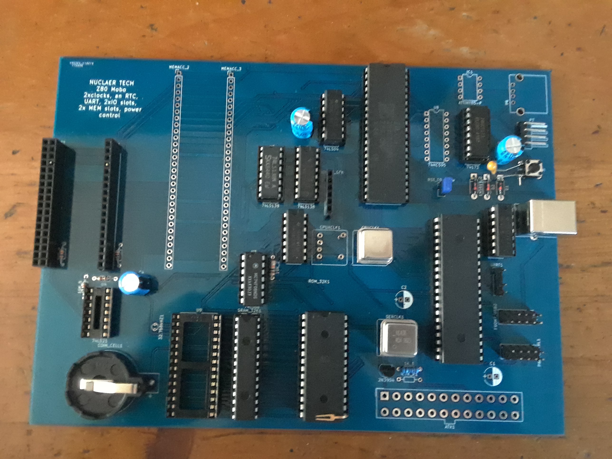
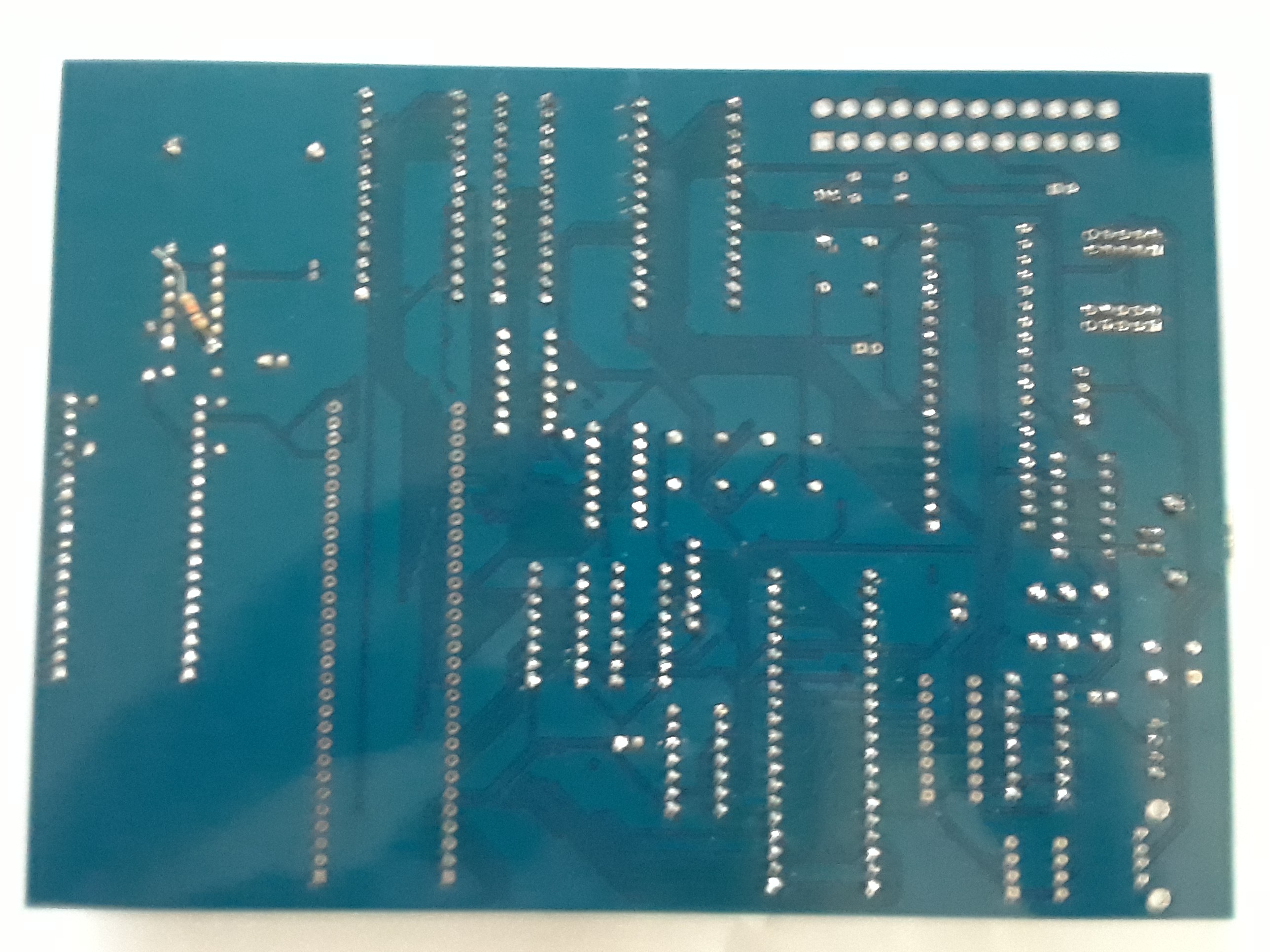
    The new mobos somewhat work!  I am still compiling a list of things to fix, as the first boards always have problems (at least for me so far).

    Here are some pics:

    The board supports UART, 32KiB of RAM and 32KiB of ROM, a bq4845 RTC, ATX power, 4 expansion slots, and two different clocks for the CPU (switchable).  With an ATtiny a USB keyboard can be added.  There are more bells and whistles, but most of the features I listed aren't tested.  I don't have a bq4845 (I ordered 4, but they sent me 4 bq3285s instead).

    There are a lot of awesome things, but the board isn't perfect.  There are a few pullup resistors I forgot, and it doesn't have any LEDs ;(.  I am making a to do list for my next boards, don't worry.

    I also need to make that uPD7220 graphics card... I may need to actually order a board for that.  I would be worried about that however, because if a make a little mistake... there goes some money for nothing.  The embarrassing fact is that I don't have enough patience to solder the wires for a complex TTL circuit.  When I build that this machine will be incredible, especially considering that it should be possible to boost this thing up to 20Mhz: the graphics and CPU would be crazy powerful; really exciting.

    Unfortunately CF cards and IDE drives don't like any of my z80 computers, so I cant really do anything with files yet.  Without a file system an OS isn't super useful, so a CF card reader is the next step.

    The reason that I am building this computer to be so nice and powerful, even though it uses (largely) 80s tech, is that I want a platform to build an OS on.  And of course because building a computer completely from scratch.  The problem with modern computers is that they are too complex to fully understand from books, difficult to program on without an OS, and pretty much are impossible to completely build from scratch at this point.  A mixture of simpler, older tech with modern technology that works well with it is the perfect solution.  The computer can be fairly powerful, yet easier to program and construct.

    With that, here is a video of it working, plus a few more tidbits:

  • ORDER​ED THE MOTHERBOARDS.

    Dylan Brophy09/12/2017 at 04:29 0 comments

    My old boards were an incredible step forward, but they had limited functionality, were not built with power/input/simplicity in mind, sometimes were unreliable, and were starting to die.

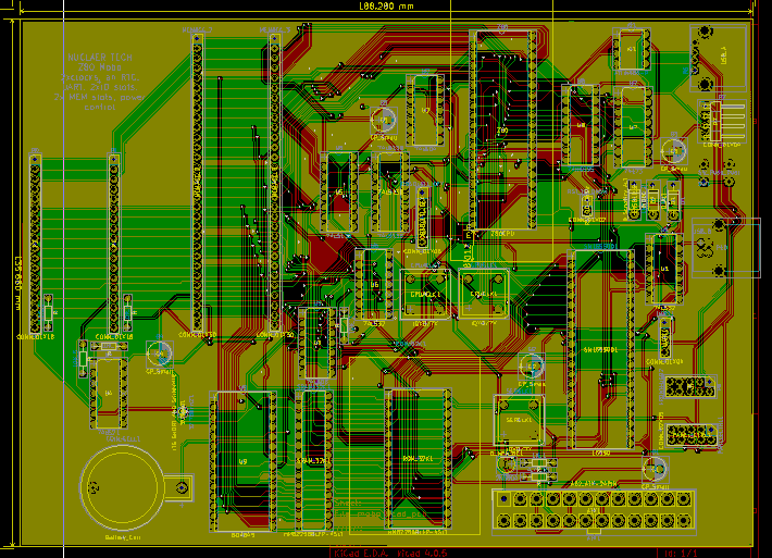
    The new boards have proper ground planes plus some cool new features I have been planning for longer than I can remember, including:  Changing clock speeds, an RTC, and slots for IO and memory cards.  Also it adds support for USB keyboards and an ATX power supply.  I can't wait, execpt I dont have all the connectors I need to make it do everything, but it will still be awesome when I get it.

    Here is a pic from KiCad:

    You can take a peek for yourself, I will upload the files.

    Good day Hackers!

  • everything but keyboard and CF working

    Dylan Brophy07/13/2017 at 07:12 0 comments

    CF card is untested, but there is something really wrong with the keyboard. Certain keys, mainly ones far from the control circuit, don't work. I think I also found a firmware glitch. So there seems to be a matrix problem, right? but all keys work on my test area. Hmm. That's why I am 3d printing a keyboard back, maybe if there is interference or something causing the keyboard not to work in some places, it would be blocked. At least the video is working great!

    No pic today ;( oh well

  • Graphics and a keyboard in the works

    Dylan Brophy07/07/2017 at 07:48 0 comments

    Got basic graphics working; I essentially took one of the NGT20's predecessors and updated the firmware for better graphics.

    More exciting : the UART keyboard!

    I typed that on a home made mechanical keyboard! Nice and clicky... still am building the card that connects to the Z80 computer. I cant use the other UART as input because the graphics card uses the port. I mean, I could hack it, but... Actually I think I'm going to do that. Lol. Time to hack a graphics card and keyboard port!

  • ITS ALIVE!

    Dylan Brophy06/28/2017 at 23:33 0 comments

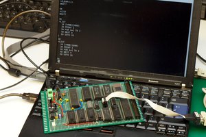
    UART FIXED! I hadn't soldered the oscillators ground line, so the UART chip had no clock signal. Duh. Anyways, I had written an OS with the help of an emulator I think starting about a year ago. Here is a branch of it running on my Z80 computer:

    Still a long ways to go. Next step: graphics!

    You see, the NGT20 is one of a line of video-card-like devices I made. My Z80 computer has been designed for a long time to be compatible with one of its unnamed relatives. I just got a CF card to IDE adapter and a CF card for files. Also, I have an RTC chip on the way so I can multitask. Lots of things happening moving forward!

  • Big ole update

    Dylan Brophy06/21/2017 at 14:48 0 comments

    OK, so for now I ditched the motherboard idea. I am not willing to buy a motherboard from a fab, so later I may make a homemade board with vias, as seen here. That blog is really awesome btw, consider reading it sometime.

    Well anyways I have been trying to get a 16550 UART working, so far with no luck. I have pretty much reduced the problem down to the UART or the data bus's connection to the 'expansion board' I made because I ran out of room on my first board.

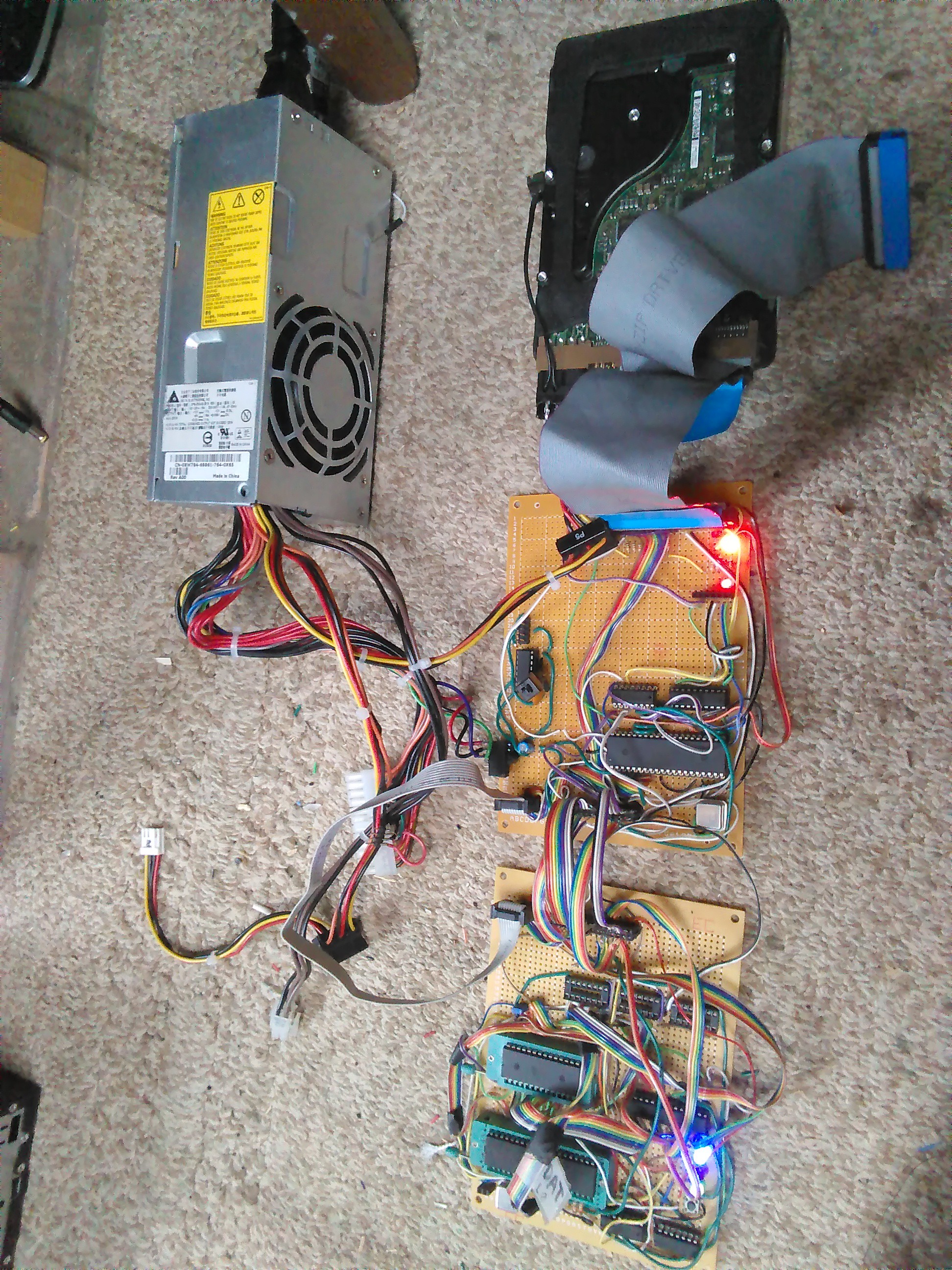
    I also added a nice ATX power supply controller circuit, which allows power to go to the (currently useless) IDE hard drive. It's still pretty cool though.

    Well, here is the system so far:

    You can see why I need to make my own smaller and more clean PSU. This 'wires going crazy shorting everywhere' business with a WAY oversized powe is beyond terrible. OK, now the computer itself:

View all 15 project logs

Enjoy this project?

Share

Discussions

SLAVKINGRED wrote 04/03/2023 at 01:02 point

this is awesome.

  Are you sure? yes | no

yedehd41 wrote 11/23/2021 at 08:57 point

There are some very good points that you mentioned here that why I think you need to visit kinds of motherboard where you will gain some more information about it.

  Are you sure? yes | no

agp.cooper wrote 06/09/2018 at 01:43 point

I use the AT29C256 (90ns) for my DIY CPUs. It is 32k x 8 and incircuit programmable. The page size is 64 bytes. I made up a programmer board using an Arduino Nano (obviously I cannot program the whole 32k with this set up unless I use serial upload). These should work well with your project.

  Are you sure? yes | no

Dylan Brophy wrote 06/09/2018 at 01:48 point

I would use something like that, but this is for a filesystem that really needs at least 4 megabytes of storage...  I might make a SPI master in ttl and use a flash IC.

  Are you sure? yes | no

Dylan Brophy wrote 06/08/2018 at 17:05 point

@Julian I have not looked at FRAM in the past, but now I will!  The only issues are cost and density.

Also, I see you have a similar project, perhaps we can share ideas!  I was also considering using a battery and static RAM chips - but the same limitations still apply I suppose.  Maybe I need to design a SPI controller for the Z80 bus for interface with spi memory chips.

  Are you sure? yes | no

Hacker404 wrote 09/12/2017 at 02:16 point

If you want more speed then FLASH is much faster than EEPROM and easier to program - even the CPU can write to FLASH.

I normal FLASH chip is about 70nS and there are faster chips but they are more specialized. You can still get 1 Mib (128 kiB) FLASH chips in DIL / DIP format.

This project is coming together well !!!

  Are you sure? yes | no

Dylan Brophy wrote 09/12/2017 at 04:17 point

Thank you!  Yes I have tried to use FLASH in the past but write protection has caused problems...  I want the EEPROM/BIOS to be modifiable via the CPU.  I think flash is best for high density,  I'm thinking about using it for a special SSD drive that connects directly to the Z80's IO. I guess I could create some really cool software abstraction to make modifying the FLASH chip unnecessary and thus give faster speeds with the same functionality.

Actually, I used EEPROM originally because I couldn't program FLASH, but that has changed.... I've just stuck with the "32KiB EEPROM model."

I have something new to think about :D

  Are you sure? yes | no

Hacker404 wrote 09/12/2017 at 09:54 point

By SSD, I assume you mean IDE.

I tried IDE and it was a nightmare as I was using Compact Flash (CF) that has an IDE mode but it turned out that CF needs CMOS voltage levels and I was using a LVTTL CPLD. I plugged in a HDD instead of the CF and it finally worked.

If you are going to use IDE then here are the traps -

IDE stands for Embedded  Drive Electronics and IDE came out with the 8-bit XT. It was also used for the 16-bit AT.

There are 8-bit and 16-bit versions of IDE so people assume that the 8-bit relates to the XT and the 16-bit relates to the AT and that is not true at all.

The 8-bit IDE version was an 8-bit mode that was used on the 16-bit AT. The XT was completely different.

Apart from that if you get the voltages right and set the mode registers right and use LBA instead of CHS then all is good and it works well with a 8-bit Z80 bus.

The best place for IDE specs is the CF specification of version 3 or less that has the IDE mode included.

The FLASH chips aren't hard to use from memory you just need to do some prewrites to AA00 or something like that.

Here's some Arduino code for FLASH

It's was used with a CPLD as a shift register so it has serial_out but you can do the same with a parallel address / data bus of the Z80 -

void signal_delay()
  {
  //  This may be needed for long wire connections
  //delayMicroseconds(10);
  }

void sector_erase_delay()
  {
  delay(20); // 10mS
  }

void chip_erase_delay()
  {
  delay(40); // 20mS
  }

void write_delay()
  {
  delayMicroseconds(60);
  }


int read_address(long add)
  {
  int one_byte;
  //      data, WE, OE, CE, address
  //serial_out(0, 1, 1, 1, 0);
  //serial_out(0, 1, 0, 0, add);
  //serial_out(0, 1, 0, 0, add);
  serial_out(0, 1, 0, 0, add);
  toggle_S_LOAD();
  one_byte = serial_in_byte();
  return one_byte;
  }

void write_address(long add, int data)
  {
  //      data, WE, OE, CE, address
  serial_out(0xAA, 1, 1, 0, 0x5555);
  serial_out(0xAA, 0, 1, 0, 0x5555);
    serial_out(0x55, 1, 1, 0, 0x2AAA);
  serial_out(0x55, 0, 1, 0, 0x2AAA);
    serial_out(0xA0, 1, 1, 0, 0x5555);
  serial_out(0xA0, 0, 1, 0, 0x5555);
    serial_out(data, 1, 1, 0, add);
  serial_out(data, 0, 1, 0, add);
    serial_out(data, 1, 1, 0, add);
    write_delay();
  }

void sector_erase(int sector)
  {
  sector = sector & (total_sectors - 1);
  sector = (sector << 12);
  //      data, WE, OE, CE, address
  serial_out(0xAA, 1, 1, 0, 0x5555);
  serial_out(0xAA, 0, 1, 0, 0x5555);
    serial_out(0x55, 1, 1, 0, 0x2AAA);
  serial_out(0x55, 0, 1, 0, 0x2AAA);
    serial_out(0x80, 1, 1, 0, 0x5555);
  serial_out(0x80, 0, 1, 0, 0x5555);
    serial_out(0xAA, 1, 1, 0, 0x5555);
  serial_out(0xAA, 0, 1, 0, 0x5555);
    serial_out(0x55, 1, 1, 0, 0x2AAA);
  serial_out(0x55, 0, 1, 0, 0x2AAA);
    serial_out(0x30, 1, 1, 0, sector);
  serial_out(0x30, 0, 1, 0, sector);
    serial_out(0x30, 1, 1, 0, sector);
    sector_erase_delay();
  }

void chip_erase()
  {
  serial_out(0xAA, 1, 1, 0, 0x5555);
  serial_out(0xAA, 0, 1, 0, 0x5555);
    serial_out(0x55, 1, 1, 0, 0x2AAA);
  serial_out(0x55, 0, 1, 0, 0x2AAA);
    serial_out(0x80, 1, 1, 0, 0x5555);
  serial_out(0x80, 0, 1, 0, 0x5555);
    serial_out(0xAA, 1, 1, 0, 0x5555);
  serial_out(0xAA, 0, 1, 0, 0x5555);
    serial_out(0x55, 1, 1, 0, 0x2AAA);
  serial_out(0x55, 0, 1, 0, 0x2AAA);
    serial_out(0x10, 1, 1, 0, 0x5555);
  serial_out(0x10, 0, 1, 0, 0x5555);
    serial_out(0x10, 1, 1, 0, 0x5555);
    chip_erase_delay();
  }


  Are you sure? yes | no

Dylan Brophy wrote 09/12/2017 at 13:12 point

@Hacker404 

I have actually been trying to get a CF card to work, but the status register seems to return weird values.  Could be that the CF card uses CMOS...  Maybe then my old hard drive will work.  I designed the new board to support the ATX power connector so getting power would be that much easier.

But, actually, by SSD I meant another custom board full of FLASH chips or something that works as an SSD.  I'm still looking into it, I have some designs in my notebook.

About flash... Yea.  I have some flash chips and I programmed them with an arduino, but I guess I don't like all that 0x5555 and 0xAAAA stuff.  The ones I have worked like your code; they're the SST39SF040 and some variants.

My designs make use of 8-bit IDE, but I didn't know all those traps existed.  It seems that CF cards would be designed to be completely backwards compatible since the protocol is IDE.  I guess if I want to use CF card I have to use level shifter.

Thank you for your information, I value it.  When I ask for help in a project log no one helps.  If you have anything more to say, any ideas, I am all ears.

  Are you sure? yes | no

Julian wrote 06/08/2018 at 10:31 point

"I have tried to use FLASH in the past but write protection has caused problems...  I want the EEPROM/BIOS to be modifiable via the CPU." ... have you considered FRAM?  FRAM is non-volatile but is directly writable and has speeds in the same sort of range as DRAM (60-70ns access time, 120-140ns cycle time, which is good enough to support a 20MHz Z80, which only requires access time < 1.5x clock speed and cycle time < 3x clock speed).

  Are you sure? yes | no

zpekic wrote 08/13/2021 at 03:55 point

Hi, did you consider generating the nWAIT signal depending on the address bus output? 0 waits for RAM, x states for EPROM, and CPU running at full speed? 

  Are you sure? yes | no

oshpark wrote 06/29/2017 at 19:34 point

Great project!

  Are you sure? yes | no

Dylan Brophy wrote 06/29/2017 at 20:20 point

Thankyou!

  Are you sure? yes | no

Dr PEKER wrote 04/08/2017 at 16:31 point

Hi Dylan,

At last my monitor type OS (with inline assembler and disassembler )is ready
Please setup and try this v1.0b 
you can find all necessary information in my Efex pages;


http://peker.000webhostapp.com/Efex-V4/


please send me your comments than I can improve software


Thank you

  Are you sure? yes | no

Hacker404 wrote 03/27/2017 at 10:03 point

I'd love to see more details about this project. I have some similar projects as well. 

  Are you sure? yes | no

Dylan Brophy wrote 03/27/2017 at 14:31 point

Yes! I saw the #Z80 Retro Computer (With Graphics).  I think I can learn a lot from you.  You have excellent documentation and your projects seem to be made very cleanly.  Its really nice.  I havent looked much into that project in the past but looking more into it now I think I should study it!

I haven't worked on the project in a while because I need to figure some problems out and get some more extra cash. I have the money, I just want to grow it before I spend any.  Watch for a next update though - the project is not dead and I intend on completing it.

  Are you sure? yes | no

Similar Projects

Does this project spark your interest?

Become a member to follow this project and never miss any updates