Tony Kambourakis
-
Adafruit IR Break Beam
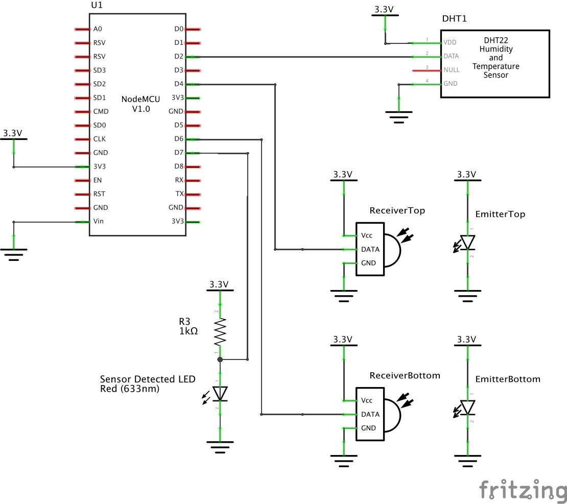
02/15/2016 at 01:19 • 2 commentsThe Adafruit IR Break Beam sensor comprises two components; an emitter that generates an IR beam and a receiver that is sensitive to the IR beam. When the beam from the emitter is broken the receiver pulls its digital output low. The receiver's digital output is open collector therefore the input mode for D4 and D6 were set to INPUT_PULLUP to keep them normally high.
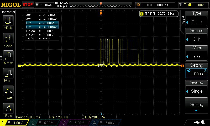
![]() There are two IR break beam sensors, one for the top slot and one for the bottom slot of the letterbox. The scope shot below shows both sensors being triggered at the same time.
There are two IR break beam sensors, one for the top slot and one for the bottom slot of the letterbox. The scope shot below shows both sensors being triggered at the same time.![]()
Both sensors normally hovered around 3.3V. They exhibited a little bounce which is taken care of using software debouncing.
An interrupt was attached to each input triggered on the falling edge.
void init_letter_sensor() {
  Serial.println("Initialising letter sensor");
  pinMode(D6, INPUT_PULLUP);
  pinMode(D7, OUTPUT);
  pinMode(D4, INPUT_PULLUP);
  pinMode(BUILTIN_LED, OUTPUT);
  attachInterrupt(D6, letterBottomSensorActivated, FALLING);
  attachInterrupt(D4, letterTopSensorActivated, FALLING);
  digitalWrite(D7, LOW);
}
As you can't pass a parameter to an interrupt handler two interrupts were created, one for top and bottom. An LED was driven from D7 to indicate when either IR beam's were broken.
The interrupt handlers simply update a global state variable that, when changed, is handled within the main loop() routine.
void letterBottomSensorActivated() {
  state = LETTER_SENSOR_DETECTED;
  letterSensorDetected = LETTER_BOTTOM_SENSOR;
}

void letterTopSensorActivated() {
  state = LETTER_SENSOR_DETECTED;
  letterSensorDetected = LETTER_TOP_SENSOR;
}
When a letter sensor is activated it will publish an event with a payload indicating top or bottom sensor. Separate topics were created to separate temperature readings and letter sensor events.
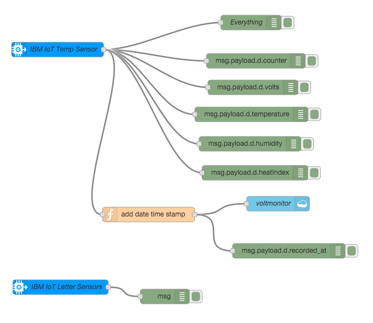
// temperature sensor event topic

char tempsensortopic[] = "int-2/evt/tempsensor/fmt/json";

// letter sensor event topic

char lettersensortopic[] = "int-2/evt/lettersensor/fmt/json";
The NodeRED flow was changed to accommodate the different topics. A second IBM IoT node was added and the original IBM IoT node was changed to only take in temperature sensor events.
![]() The Temp Sensor node only listens for tempsensor events.
The Temp Sensor node only listens for tempsensor events. ![]()
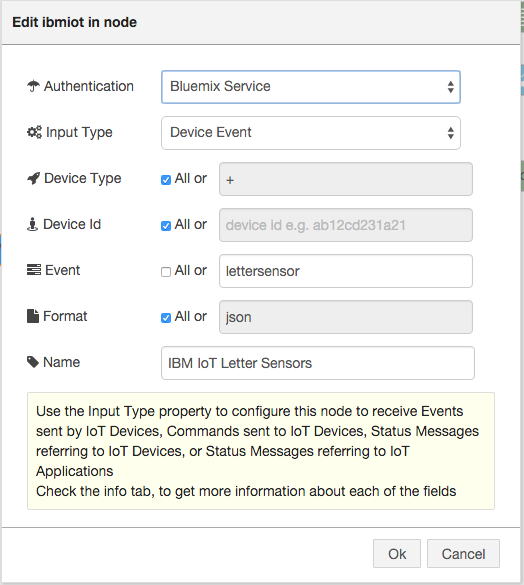
The Letter Sensor node only listens for lettersensor events.
![]()
A timer was also introduced to trigger reading the DHT22 temperature and humidity sensor. The os_timer_t was set to complete at 15 seconds and repeat.
os_timer_t myTimer;
bool timerCompleted;
void setup() { // ...other setup code os_timer_setfn(&myTimer, timerCallback, NULL); os_timer_arm(&myTimer, 15000, true); }Again the timer handler routine simply sets a global state that is handled within the main loop() routine.void timerCallback(void *pArg) { timerCompleted = true; }The current consumption with these components was as follows:State Min Current (mA) Average Current (mA) Max Current (mA) Power Supply (V) Idle 53.5 65.2 104.9 3.3 Top Sensor Active 107.5 Bottom Sensor Active 107.5 Both Sensors Active 108.0 Chopsticks came in handy to hold up the emitter and receiver units. This was also the first time OTA firmware update was used.
![]()
Refer to the IR Break Beam branch for the code
-
DFRobot Digital Vibration Sensor V2
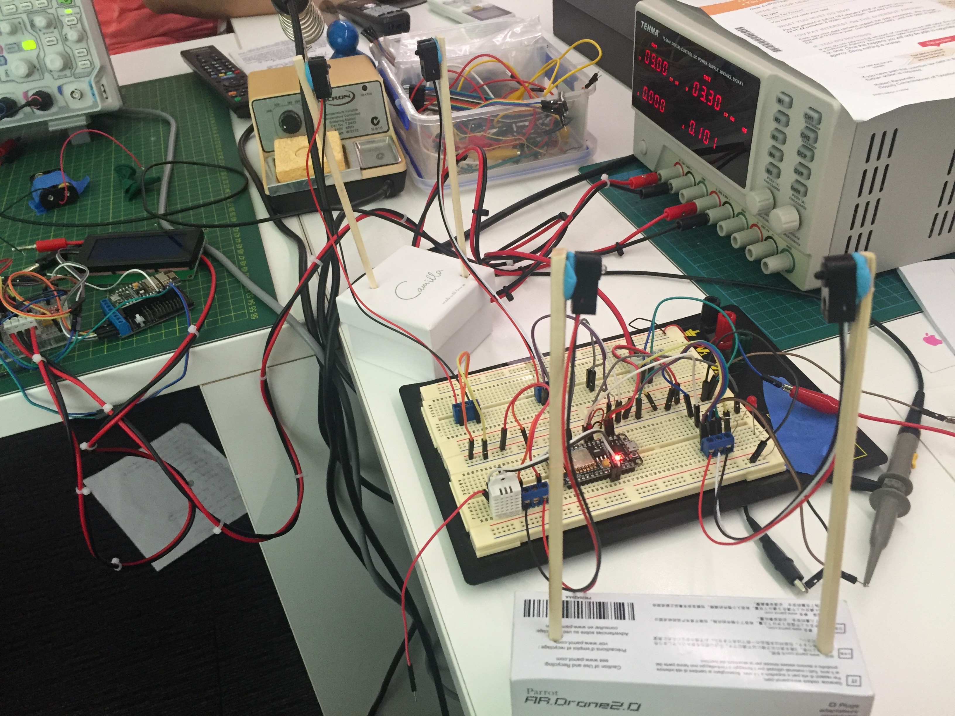
02/07/2016 at 14:26 • 1 commentThe DFRobot Vibration Sensor uses the same type of coil mechanism inside to detect vibration. This sensor has a normally-high digital output which goes low during a vibration. I took the MCU with the sensor out for a field test with my letterbox. An LED was wired to switch on when a vibration was detected. Whilst knocks and taps were detected, inserting letters and pamphlets into the top tray did not cause a strong enough vibration to be detected by the sensor. Power was supplied by 2xAA batteries.
![]()
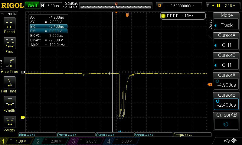
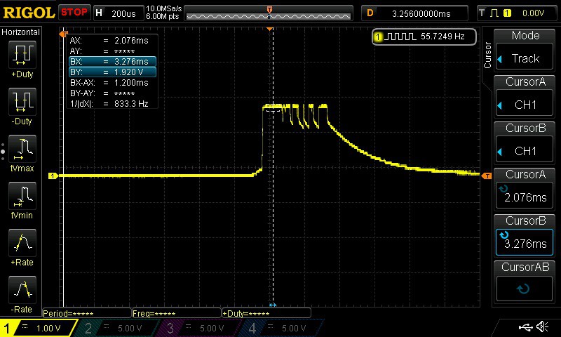
The following scope shot shows the signal on D6 when the vibration sensor is triggered. There was approximately 250ms of bounce.
![]()
The initial transition low was distinct with a drop of 2.88V down to 0V and adequate to trigger the FALLING interrupt on the MCU input pin.
![]()
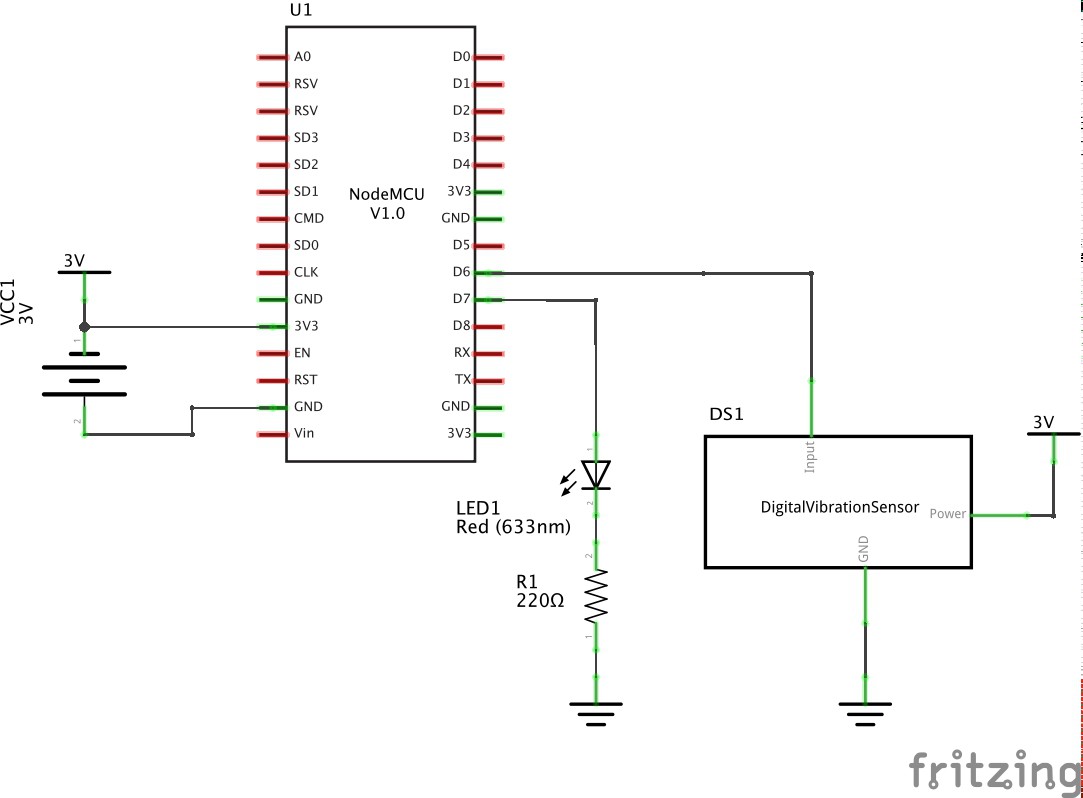
The sensor was attached to D6 with an interrupt used to detect the falling edge. See the dfrobotvibrationsensor branch for the code changes.
void init_letter_sensor() {
  pinMode(D6, INPUT);
  pinMode(D7, OUTPUT);
  pinMode(BUILTIN_LED, OUTPUT);
  attachInterrupt(D6, letterSensorActivated, FALLING);
}
With the DFRobot Digital Vibration Sensor setting its output normally high, it is a slight waste of power.
For the Adafruit vibration sensor tests I tied it low and saw the spikes going high when vibration was detected. Whilst it certainly wasn't a clean transition it was sufficient to be detected by the MCU input pin as a change in state with the interrupt.
I suspect a more sensitive vibration sensor may be prone to false positives due to strong wind. That would be unacceptable. There is one final test to perform with an alternative vibration sensor that I have on order. It is a piezo based sensor and should be a little more sensitive. However, it may result in false positives.
![]()
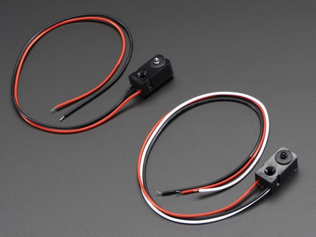
The final solution that I believe will have close to 100% accuracy is an IR break beam sensor, also on order. This can be mounted across the openings of the letterbox (centre) to detect anything coming through that cuts the beam.
![]()
-
Migrating to Platform.io IDE (Atom)
01/31/2016 at 01:08 • 0 commentsMore structured details to come. Some quick notes:
- Copy the original Arduino .ino file to Platform.io IDE on Atom may cause build issues. Create a new .ino file using PIO IDE and then copy/paste source code from Arduino .ino file to new .ino file.
- The packet size of the MQTT client needed to be increased from 128 to 256. This is in the PubSubClient.h header file located in .pioenvs/nodemcu/PubSubClient_ID89
- The following libraries were added:
- 19 Adafruit-DHT
- 89 PubSubClient
-
Vibration Switch
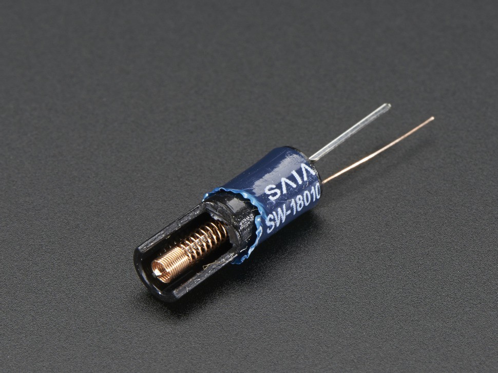
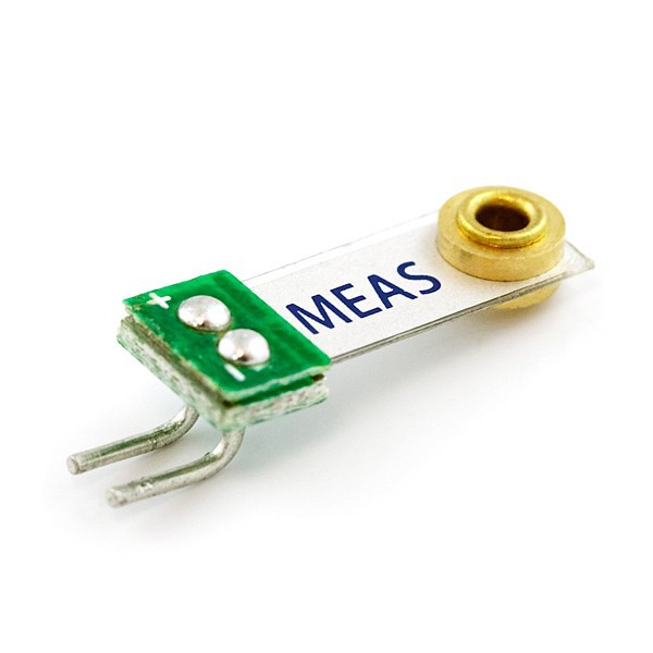
01/08/2016 at 01:12 • 1 commentTried the Adafruit vibration switch (purchased from Core Electronics) to see if it can be used to detect the insertion of a letter/package in the letterbox. It comprises a metal pin with a soft spring coiled around it. When it is moved the coil touches onto the pin, essentially behaving as a switch.
I connected it to a resistor and LED to observe the waveform when it makes contact.
![]()
It generates quite a few pulses due to the bounce. It doesn't look like the pulse has a large enough rising edge to trigger the GPIO of the MCU. This needs to be tested.
![]() Here is a shot of the inside of the vibration sensor
Here is a shot of the inside of the vibration sensor![]()
The Smart Letterbox
Attach a device to an existing letterbox that will send a push notification when a letter or package is inserted
 There are two IR break beam sensors, one for the top slot and one for the bottom slot of the letterbox. The scope shot below shows both sensors being triggered at the same time.
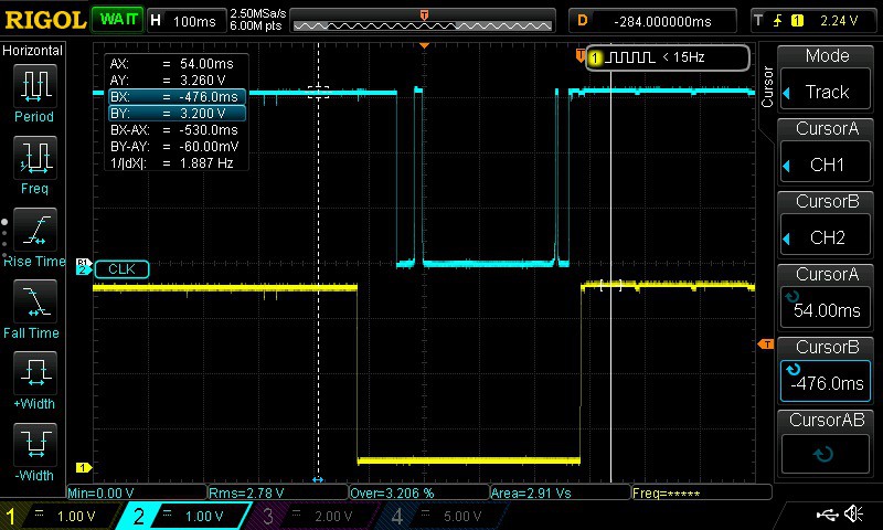
 The Temp Sensor node only listens for tempsensor events.

 Here is a shot of the inside of the vibration sensor