Close
0%
0%

MSP432 RGB LED Panel Controller

A simple controller for the RGB LED panels found at Sparkfun and Adafruit, using the new MSP432 ARM microcontroller.

Similar projects worth following
This project uses the TI MSP432 ARM MCU to drive the RGB LED panels commonly found on Sparkfun (https://www.sparkfun.com/products/12583) and many other electronics sites. The MSP432 has many peripherals that allow me to offload much of the "display management" tasks, freeing up the main CPU to do more graphics processing. This project has involved a whole suite of engineering fun stuff, including PDM modulation for full color, nested timer interrupts and state machines.

The MSP432 has a max clock of 48 MHz, which would typically be too slow to do anything fancy with a display, however my preliminary results have been optimistic. By using the USCI serial TX modules and the DMA controller and liberal use of timer interrupts, I have managed to get it working without issue at 60 FPS. I have yet to test the full performance capabilities, but I think I could push to above 100 FPS.

The hardware for this project is relatively simple. Essentially just a the MSP432 with the display connected to its eUSCI outputs and a few GPIOs. The challenging part of this project was designing the firmware in a way to leverage all of the MSP432 peripherals to reduce the computational requirements for the CPU. To do this, the firmware does the following:

  • A graphics driver subsystem comprised of:
    • Multiple timer interrupts trigger frame transmission as well as LED PDM pulse widths, etc
    • 6 eUSCI SPI peripherals with interrupts to continuously drive the display without active control from the MCU
  • DMA controller handles large memory transfers from the main program to the graphic's driver.
  • A state machine to manage events as the CPU returns from several interrupts at any given moment.

The firmware is posted on github for those looking for more details.

  • 1 × Texas Instruments MSP432 TI MSP432P401XPZ
  • 1 × 16x32 RGB LED Panel
  • 1 × Passives, LEDs, power connectors, etc

  • Hardware design

    John Boyd12/07/2015 at 04:43 0 comments

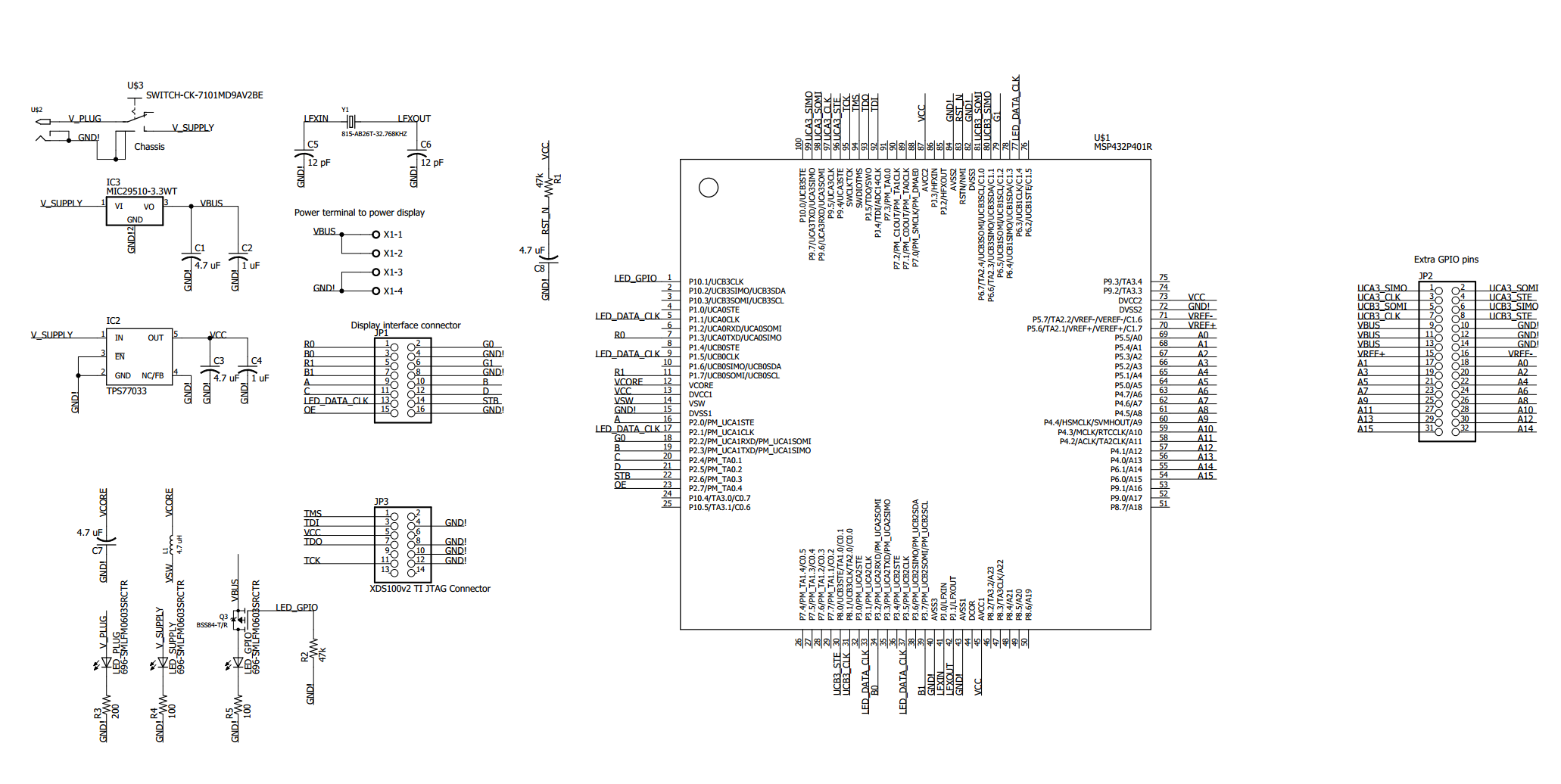
    As can be seen in the schematic, the circuit for this controller is quite simple. The key detail is that the display data lines are all connected to eUSCI serial TX/RX peripherals on the MSP432, in such a way that they all share the same clock line. This way, I can configure one of the 6 eUSCI modules as a SPI master and the other 5 as SPI slaves, causing the 5 slaves all to transmit data to the display synchronously with the master.

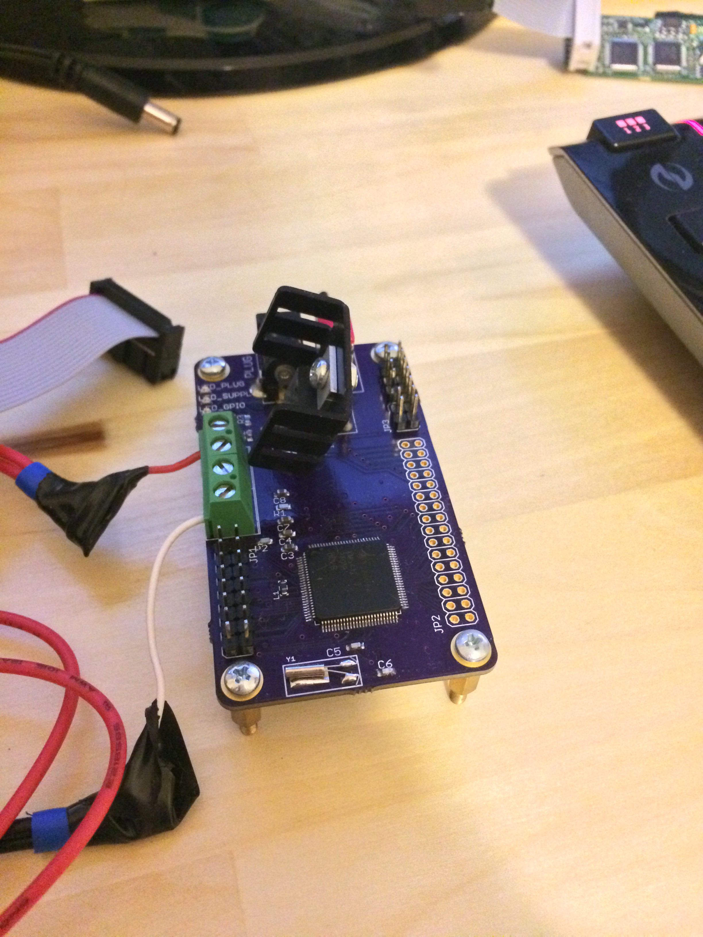
    The board design for this design is equally simple, with the only real challenge being to fit some of the large components on the board with enough clearance from each other. As can be seen in the images, there was not enough clearance between the voltage regulator and the power supply jack, when I mounted a heat-sink to the regulator. I will fix that in the repo for completeness sake, but I probably will not order another set of boards, since this one works fine.

View project log

Enjoy this project?

Share

Discussions

Similar Projects

Does this project spark your interest?

Become a member to follow this project and never miss any updates