Close
0%
0%

Oasis 3DP

A powder and inkjet 3D printer based on HP45 inkjet technology

Similar projects worth following
Oasis is a powder and inkjet 3D printer (3DP) that uses older inkjet technology to print an object. HP45 inkjet printheads jetting binder are used to bind powder locally. This part can then be cleaned and treated to create an 3D object.

3DP can print in several materials to get several results:
-Gypsum: For full color parts if printed with a color. Infiltrated with CA afterwards;
-Sand: For sandcasting moulds;
-Sugar: For edible prints;
-Ceramics: For printing stoneware. Parts need to be fired afterward;
-Metals: With a lot of post processing;

Oasis (and my other 3DP printers as well) were developed to add powder and inkjet 3D printing to the list of open source 3D printers.

Oasis is not a finished printer, rather a working prototype. Software and hardware may have quirks.

Oasis

Oasis is a open source powder and inkjet (3DP) 3D printer. It is designed to be a hackable platform to experiment with 3DP printing.

Current specs:

  • Build size: Ø84mm x 100mm;
  • Printhead: HP45;
  • Printhead DPI: 600;
  • Printhead swatch size: 300 nozzles, 0.5" (12.7mm);

Handy features:

  • A cover to keep dust out and powder in. (This may seem mundane, but was seriously lacking in my previous printers).
  • A large, flat, unobstructed build area that is easy to clean. (Again, seems mundane, is not mundane).
  • An aluminium extrusion frame where parts can easily be bolted on.
  • Plenty of room for future additions (It should be able to handle 5 printheads or a 200mm cubed print area).

Logs of interest

How 3DP

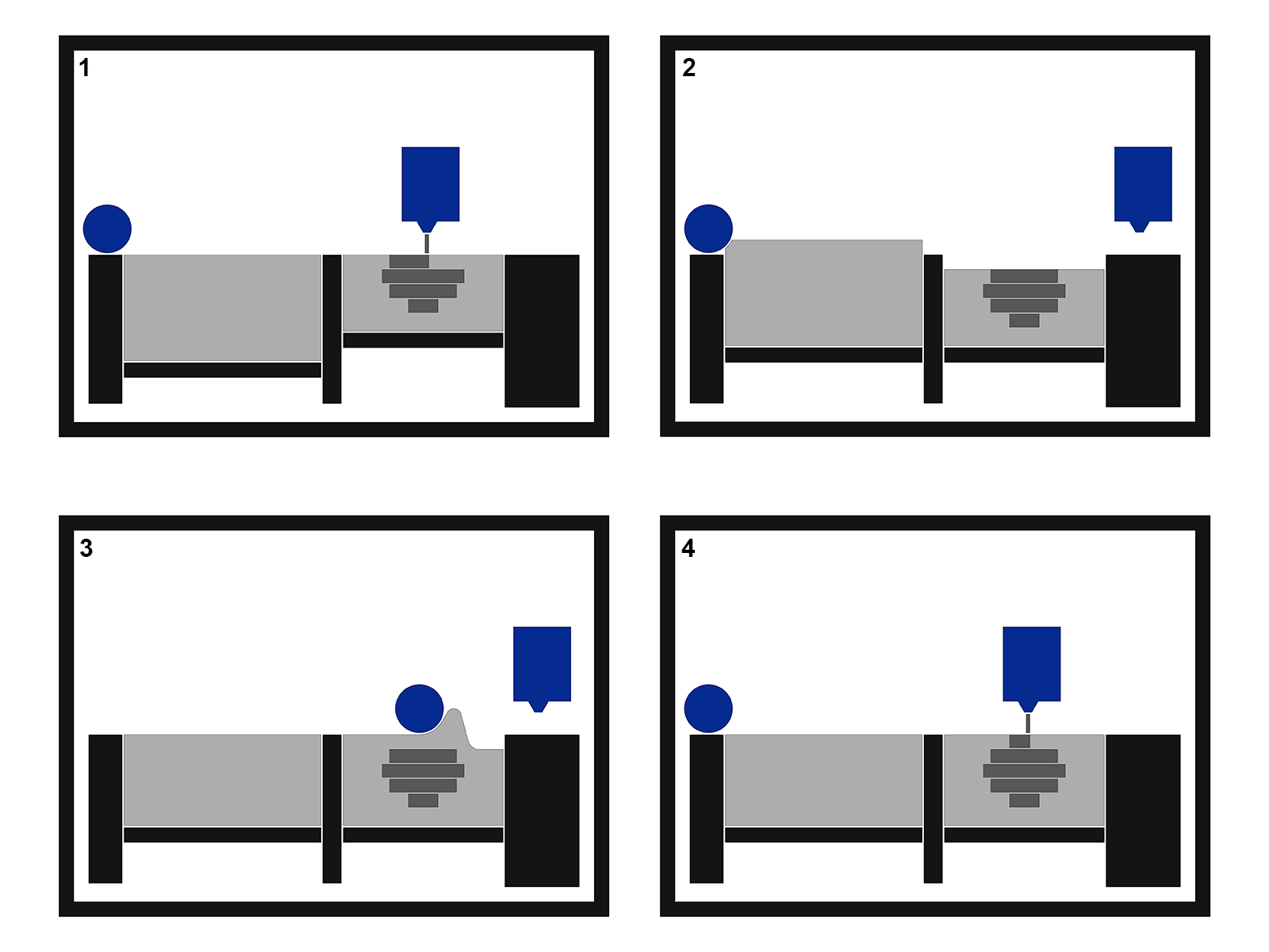
'3DP' also going by the names 'binder jetting' or 'powder and inkjet printing', is a technique that uses inkjet and powder to fabricate parts. 3DP printers consist of a moving inkjet printhead, a build area, and a way to deposit new layers of powder in said build area. The example below uses 2 hoppers and a spreader. The left hopper supplies the powder and is called the 'feed hopper', the part is built in the right 'build hopper'. A spreader can move between these hoppers to transfer powder from one to another. The order of operation for 3DP printing is as follows:

  1. The inkjet head deposits binder wherever the part needs to be. Where the binder fills the powder, the powder solidifies;
  2. The build piston lowers by the layer thickness, the feed piston raises enough to fill the build area completely;
  3. The spreader spreads the powder from the feed hopper to the build hopper;
  4. The spreader returns and the printer starts at step 1 again. This is repeated until the part is finished.

After this printing, the part is allowed some time to dry. It can then be removed from the printer and gently cleaned. After this the part can either receive further processing, or be used directly.
Why 3DP

3DP is quite unlike FDM and SLA. It's biggest advantages are:

  • You do not need support material. The powder is added one layer at a time, and the powder from the previous layers supports the next layers. All the unprinted powder can be reused infinitely.
  • A wide range of materials can be printed. While FDM is limited to plastics, and SLA requires light sensitive resins, 3DP can print most materials that come as powders.
  • Color can be printed. Because 3DP uses standard inkjet technology, it is possible to add color, simply by printing dye alongside the binder.

3DP is not perfect though, There are some drawbacks that need to be considered:

  • Powder printing is inherently messy. Very messy.
  • All prints require post processing, ranging from simple cleaning to firing or infiltrating. Untreated parts are very fragile. This also limits maximum size of parts. The part needs to be able to survive post processing.
  • All of the print area needs to be filled with powder. While the excess can be reused, a minimum amount of powder is required to print at all.
  • 3DP prints only one material at a time.
  • Hollow parts need escape holes to drain unprinted powder.

What 3DP

There are a variety of materials 3DP can print. The only thing these materials have in common is that they are powders. In most cases, a glue is added to the powder. Examples of this are PVA, sugar or maltodextrin. The binder is generally an inert liquid, like an alcohol/water mix. I have...

Read more »
Oasis make package 20220717.zip

A full package with all electronics, 3D files, drawings and software required to make one Oasis. While in combination with the 3D PDF, it should be possible to to build an Oasis, more information will be given in the instructions section. Updated schematic for the Oasis printer.

x-zip-compressed - 41.63 MB - 07/17/2022 at 16:50

Download

Oasis controller compact 20220521.zip

A newer version of Oasis controller that is more compact and has some quality of life improvements.

x-zip-compressed - 1.13 MB - 05/21/2022 at 17:53

Download

GNU GENERAL PUBLIC LICENSE Version 3.pdf

The software license for Oasis.

Adobe Portable Document Format - 77.43 kB - 09/08/2018 at 10:54

Preview

Oasis Total BOM 20181018.xlsx

A bill of material for one Oasis, to the current state of the machine.

sheet - 26.92 kB - 10/21/2018 at 08:11

Download

OA-Y00-A01-00 3D-PDF 20181014.PDF

A 3D PDF of the mechanical parts of Oasis. Slow and in a finicky format, but openable by adobe pdf reader. Good for reference.

Adobe Portable Document Format - 26.12 MB - 10/14/2018 at 13:06

Preview

View all 7 files

  • 1 × Full BOM can be found in files ("Oasis Total BOM *date*") 1 Oasis contains 128 unique mechanical parts and 40'ish electrical ones. Listing them here would be madness.

  • Some material closeups

    Yvo de Haas06/01/2022 at 17:54 0 comments

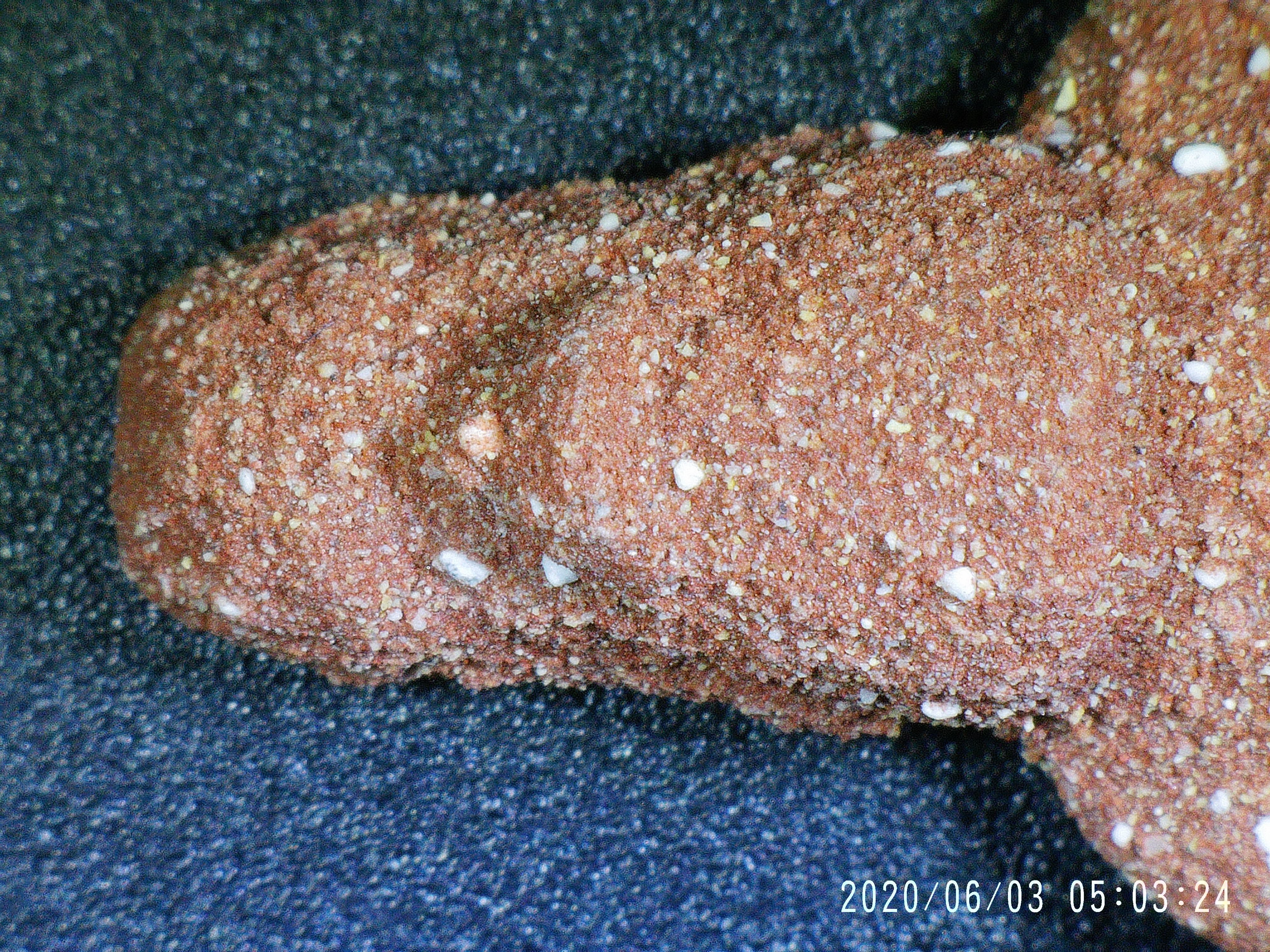
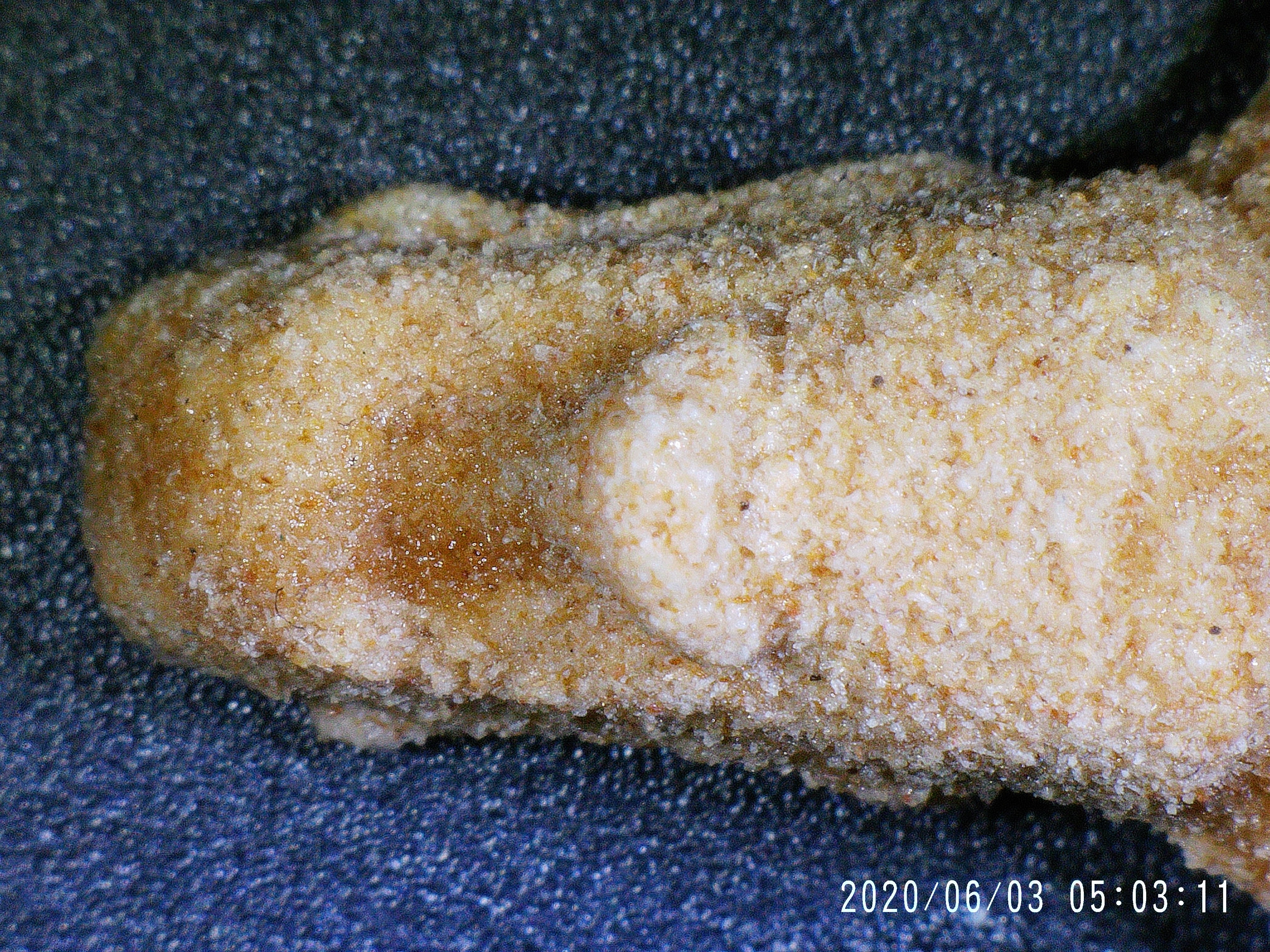
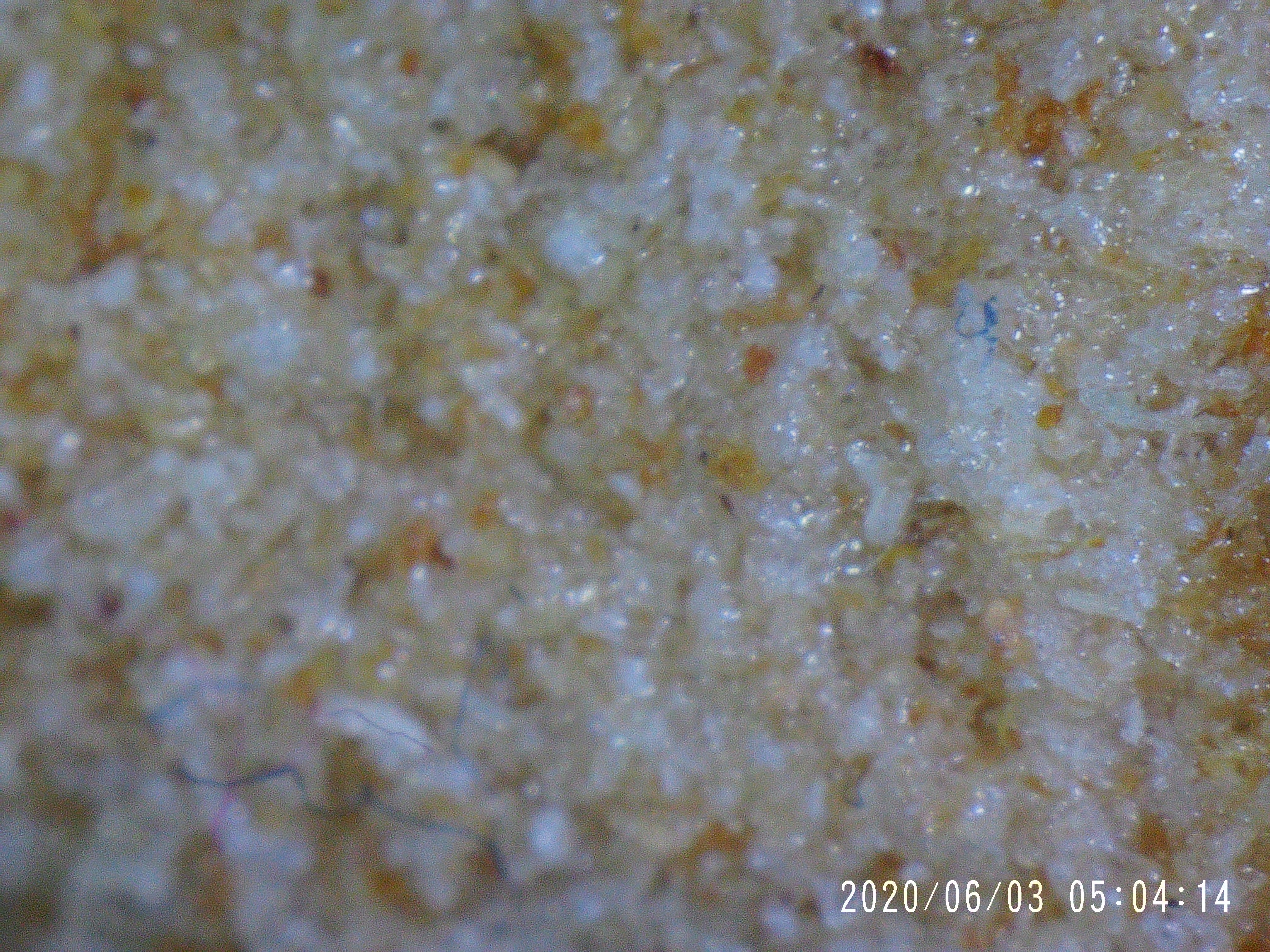
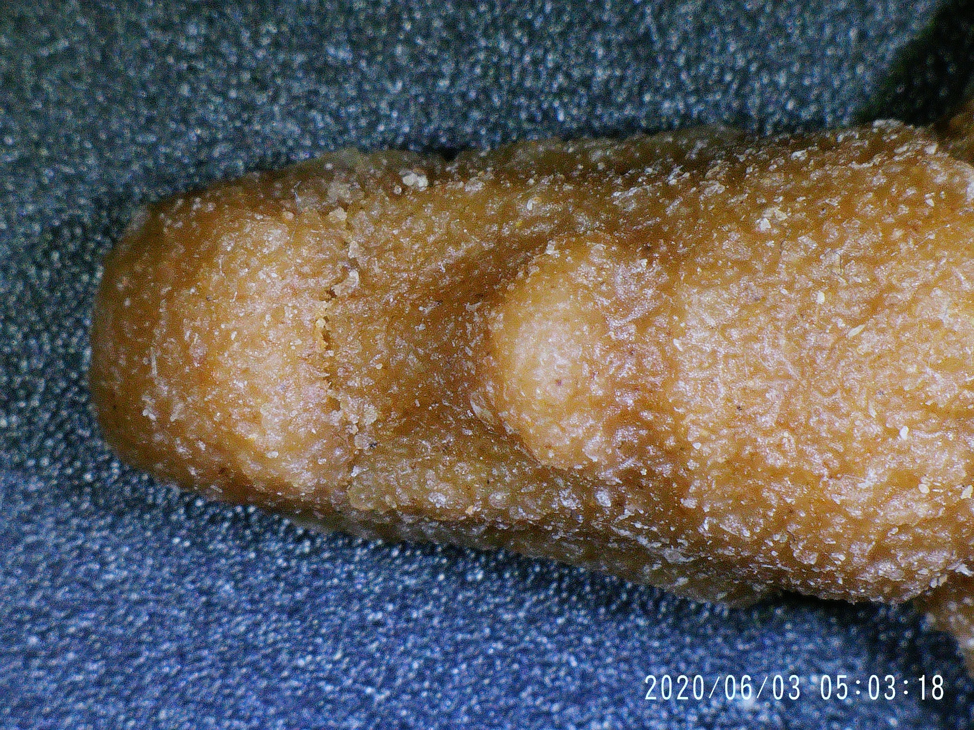
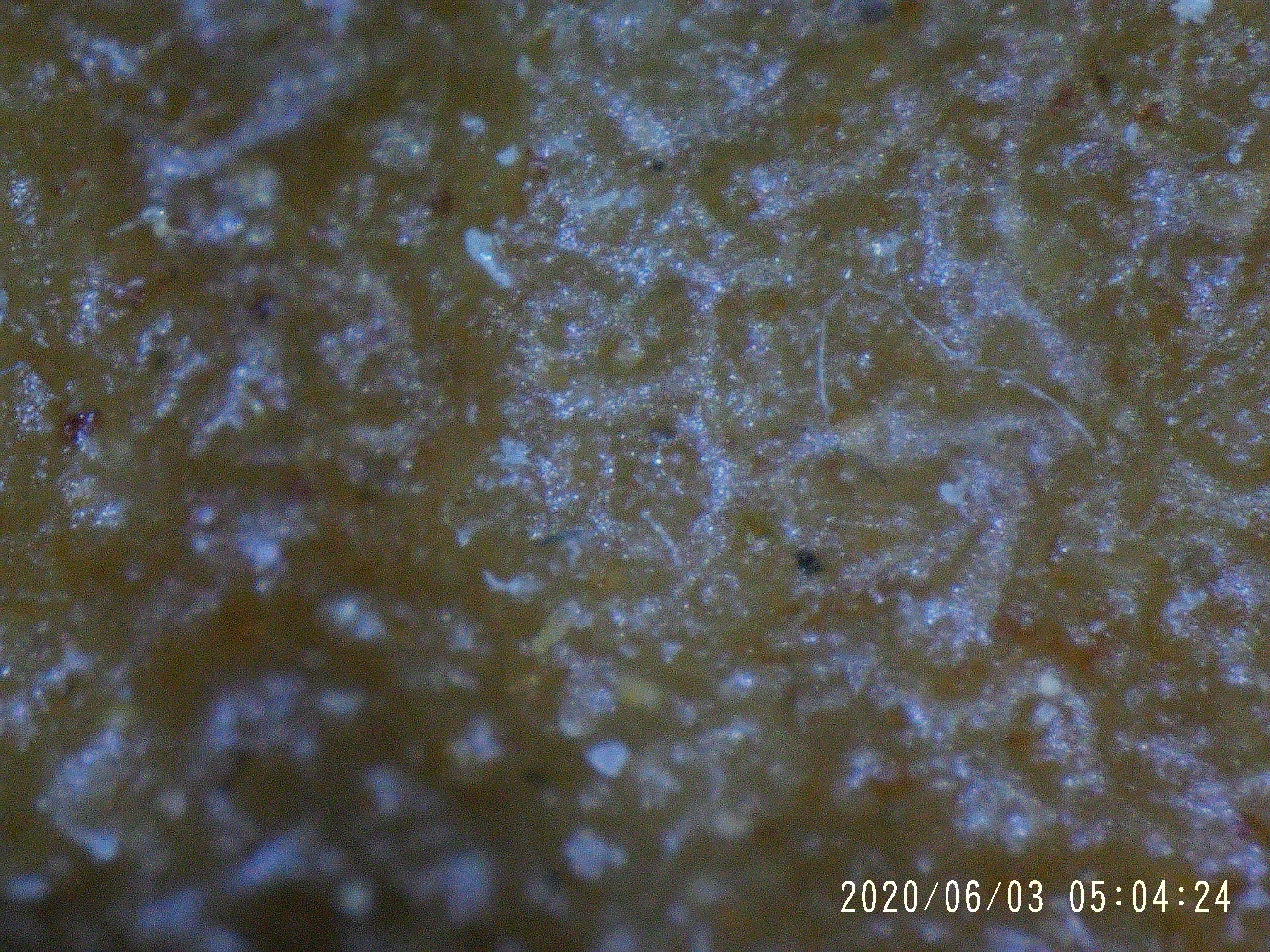
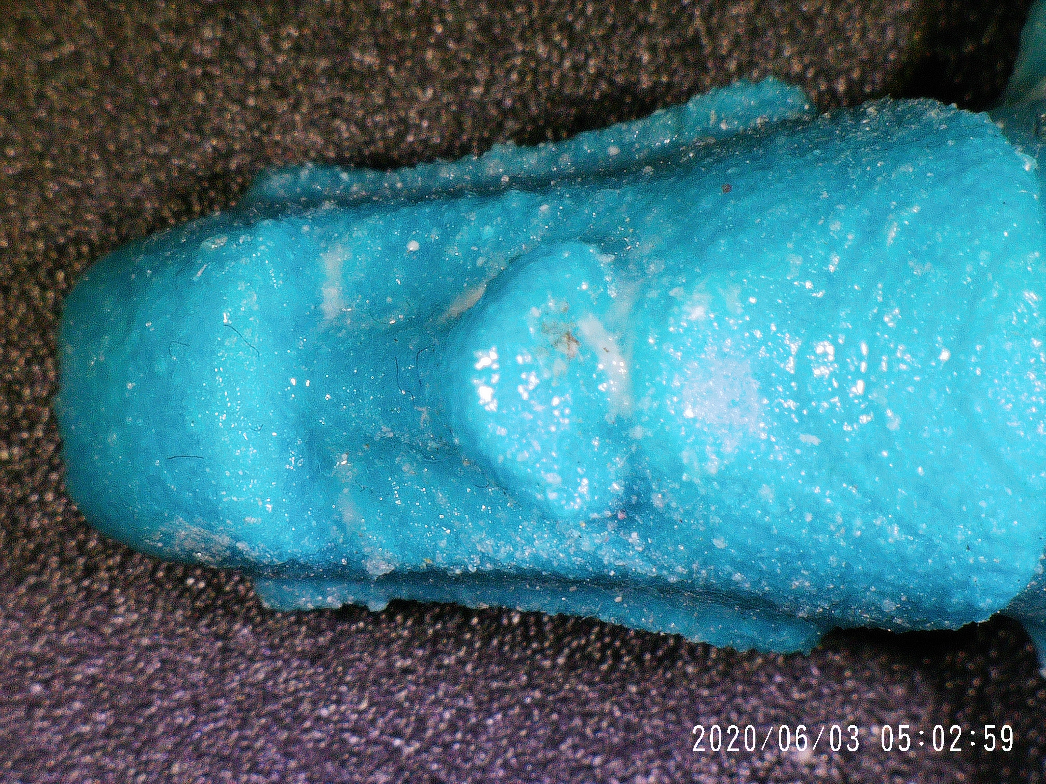
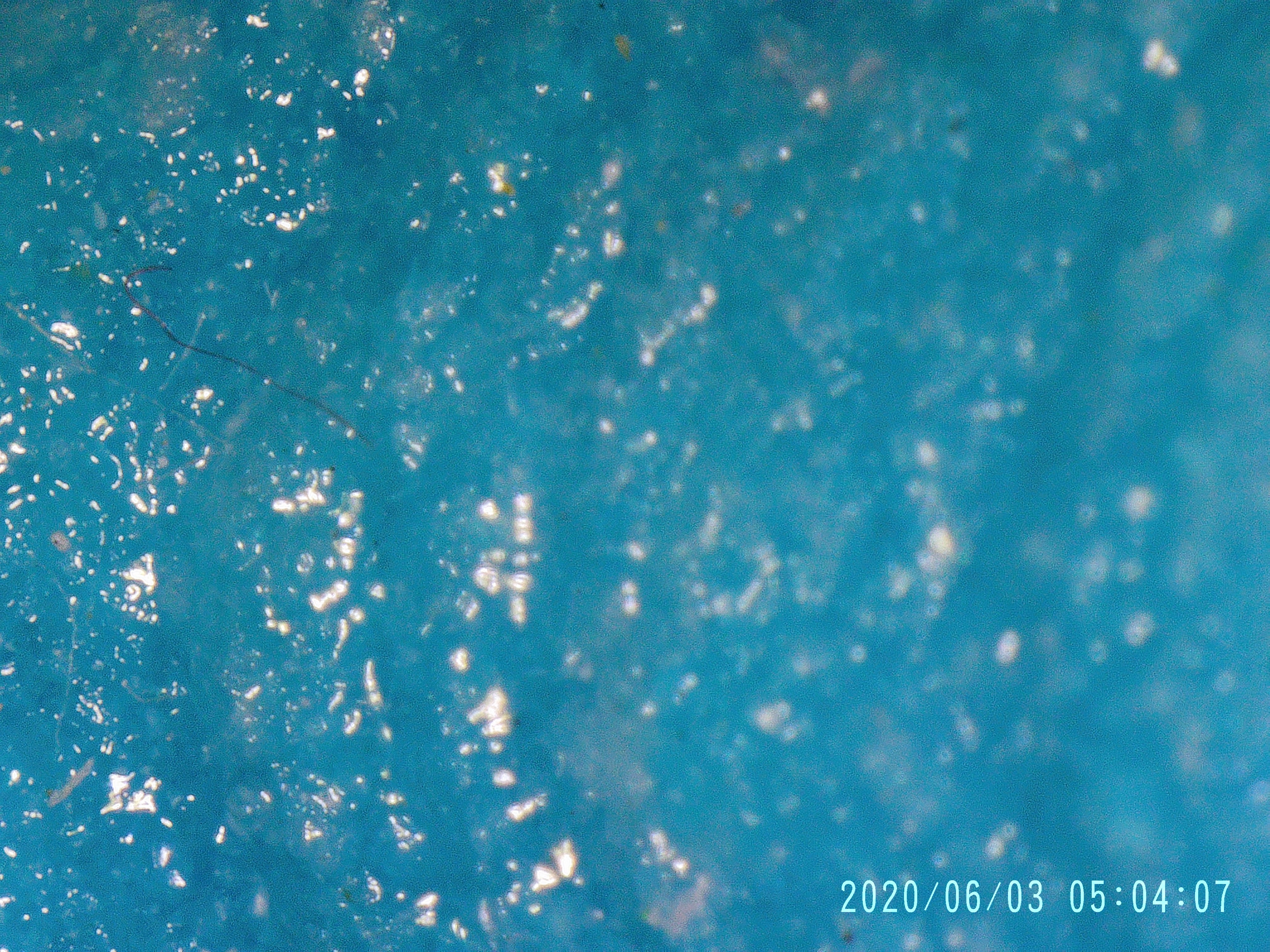
    Because it was asked, some closeups of some of the 3D prints made on Oasis.

    The first is gypsum, infiltrated with CA glue. The blue color comes from the binder, which has a small percentage blue added.

    Second is Tethon Terracotta powder. This fired in a kiln after printing.

    Last is Wood powder. The first set is infiltrated with CA, the second set infiltrated with beeswax.

  • A new Oasis software is available

    Yvo de Haas05/21/2022 at 17:58 0 comments

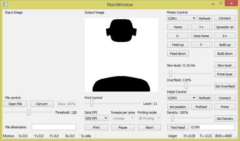
    A new version of the software to control Oasis was added to the downloads. This is called "Oasis controller compact"

    It works much the same as the old version of the software, but is more compact, has no text boxes as inputs, has selectable com ports (hit refresh if you do not see your port appear, tested in Windows, but should work on Linux) and an overfeed setting, which determines how much too far the feed piston goes up per layer added.

    None of the features are groundbreaking, but I hope it will be of some use to people who have got an Oasis running.


  • Warning! A mistake on Driver V3.01 and lower

    Yvo de Haas12/30/2018 at 10:33 0 comments

    I would add this to the instructions as well, but Hackaday.io is a bit special in that it wants me to edit ALL instructions at the same time.

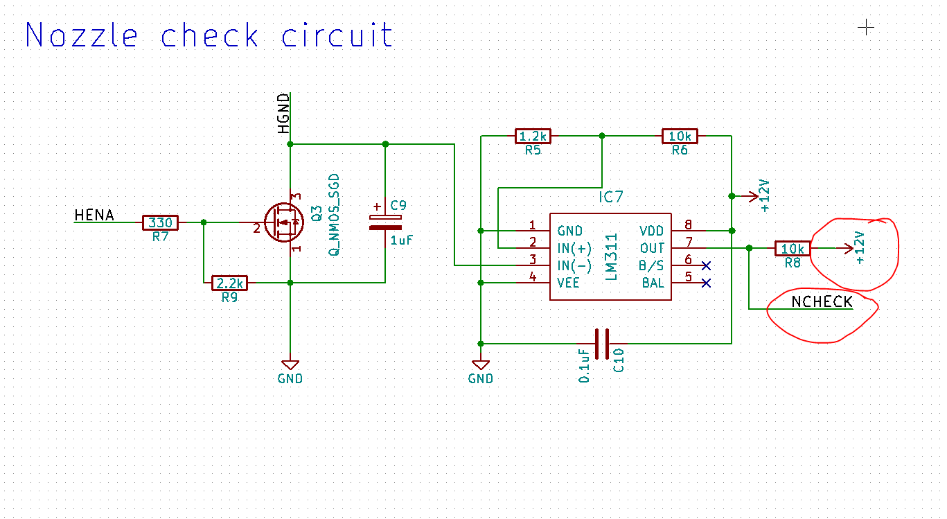
    Someone made a mistake on the driver board V3.01 (it was me). The pullup for the nozzle check signal is pulled to 12V, not 3.3V. This means that an input for the Teensy is being pulled to 12V most of the time. I myself have not experienced any issues whatsoever with this, but I suspect some other people I have been talking to have experienced issues (broken Teensy's).

    I am working right now on a V3.02 design that will pull the check to the right voltage. I advise anyone who want to make this not to use the V3.01 driver.
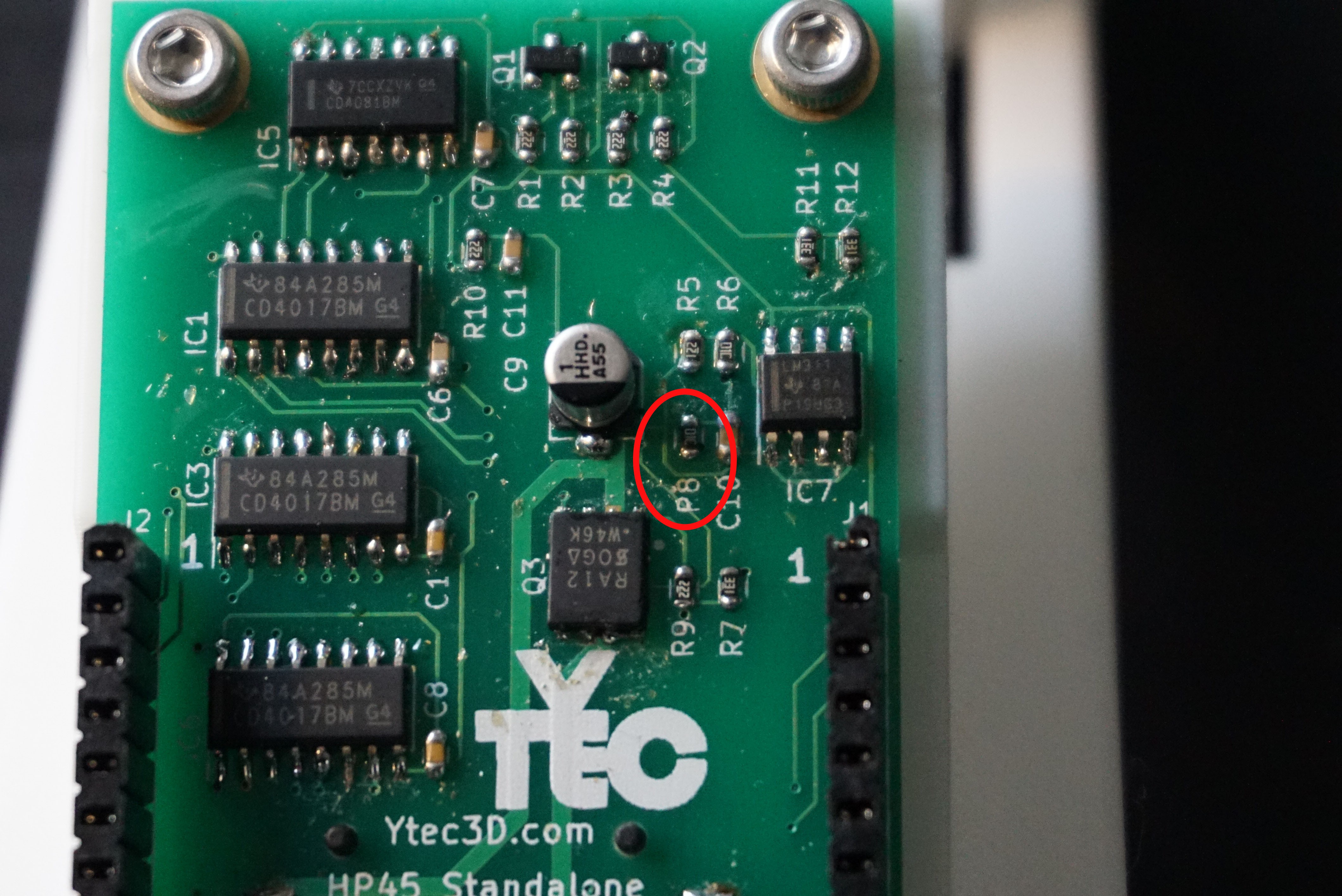
    However this new design will not fix the problem for people who already have a board. Below is a fix for this issue. TL;DR is tombstone the resistor and solder a wire to the nearest 3.3V.

    The culprit is R8 (shown here as P8, because the silkscreen is worn off). Desolder it.
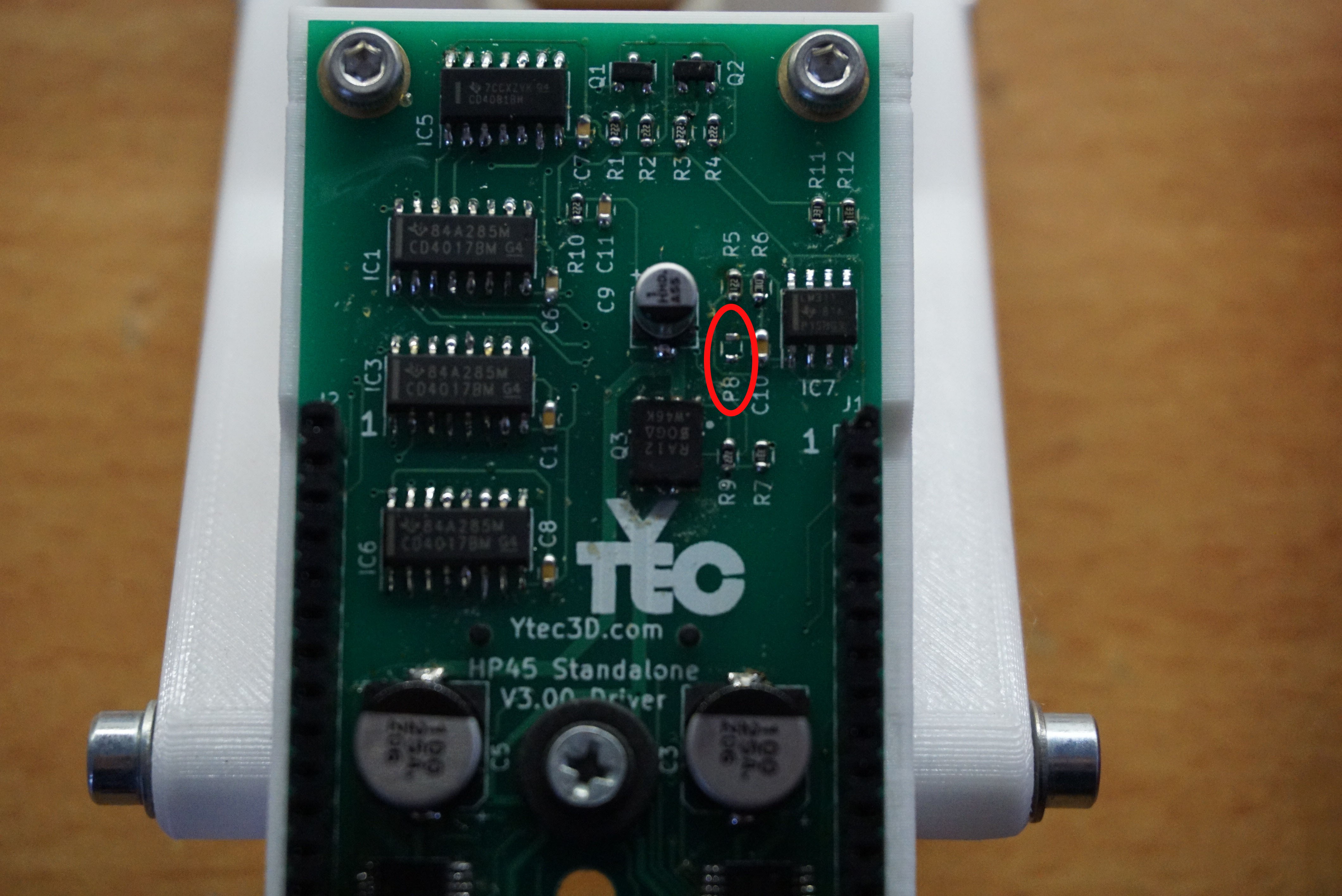
    You are now left with 2 pads. The pad closest to the R8 silkscreen is the check pin. The pad furthest away from R8 silkscreen is 12V. Solder one side of the resistor you desoldered (or another 10k resistor) with one side to the check pin, facing up (tombstoning it).
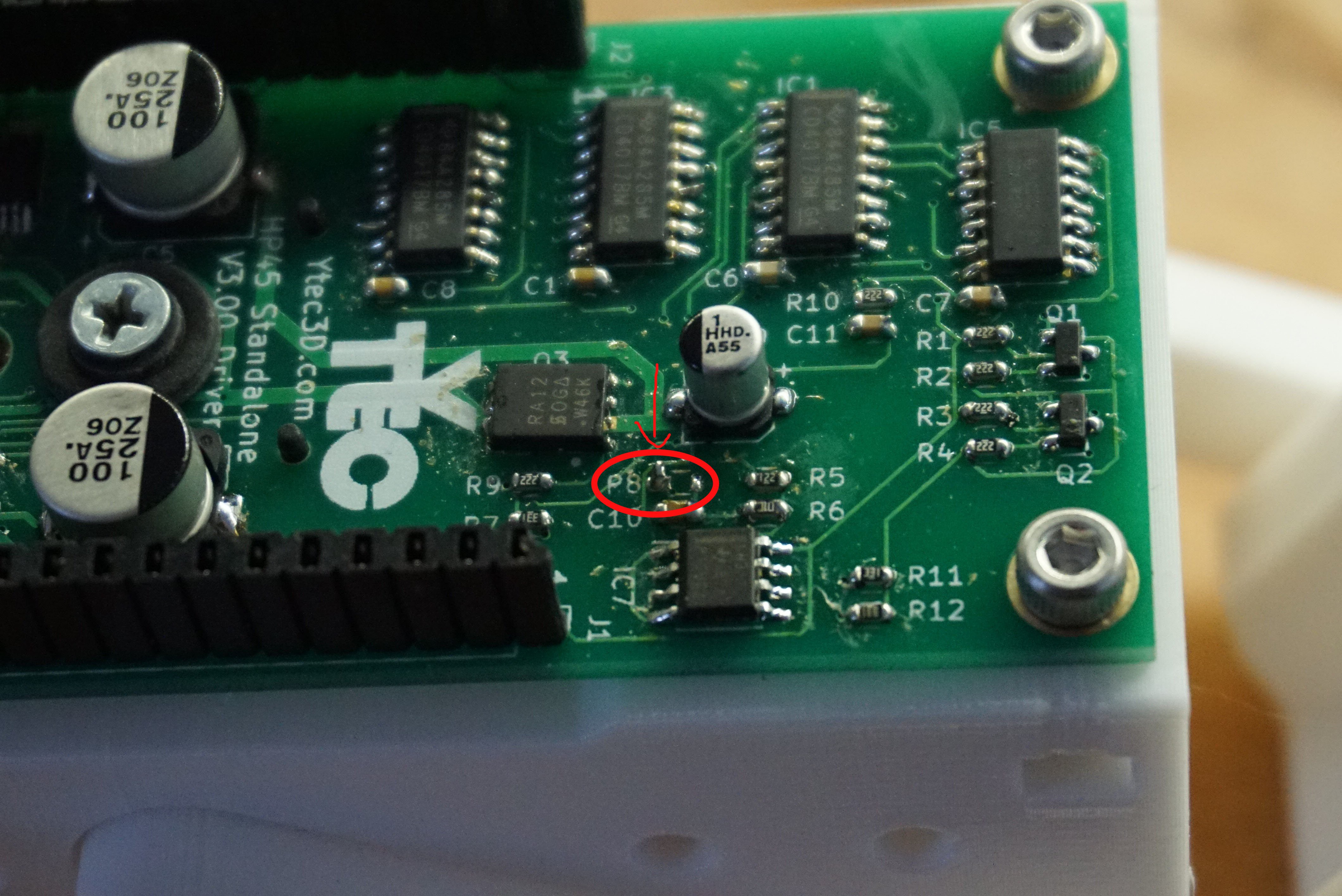
    Now a wire needs to be soldered from a 3.3V pin to the side of the 10k resistor facing up. R11 and R12 have 3.3V on the pads closest to the silkscreen. First solder a wire to the R11 or R12, then bend the wire to R8 and solder it to the side of the resistor facing up.
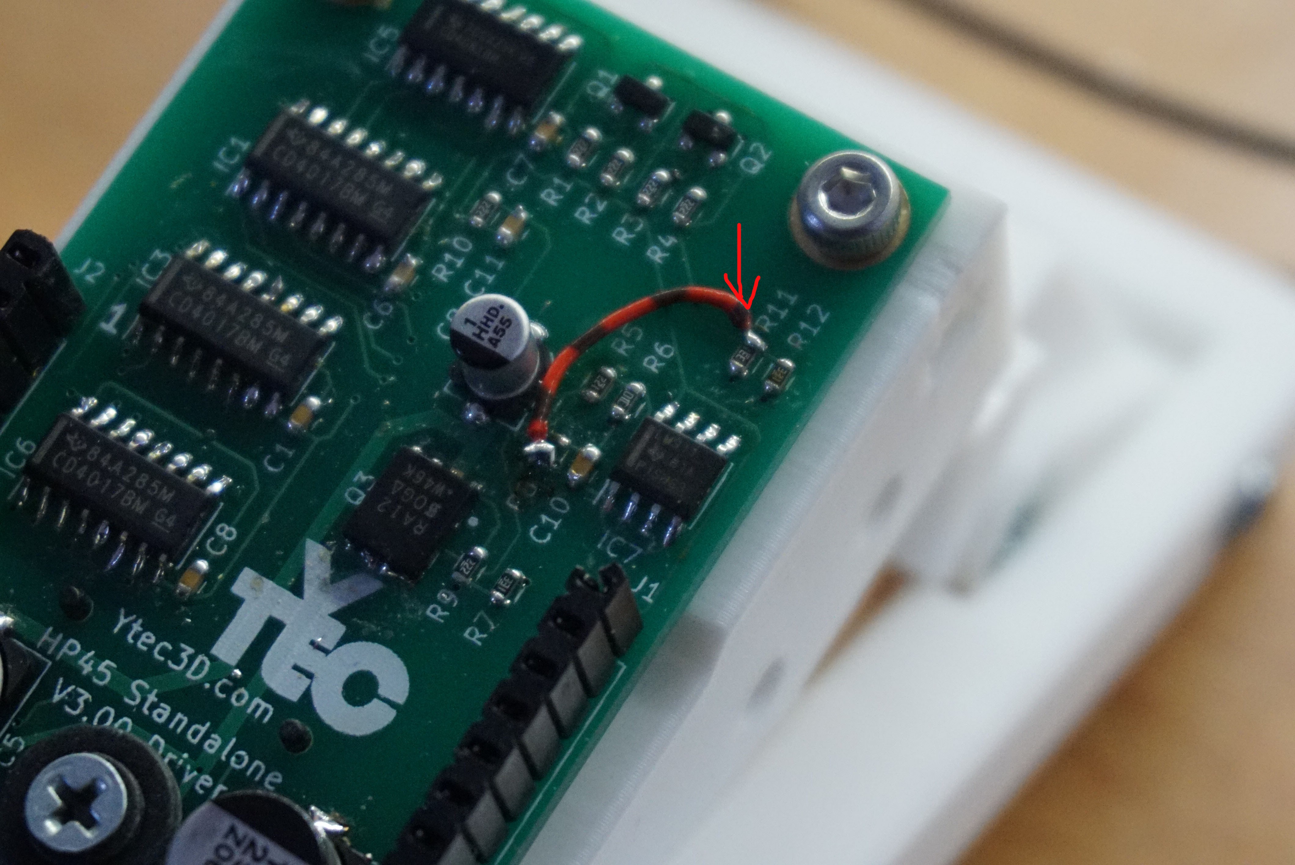
    Now the check pin is pulled to 3.3V and the check pin is no longer capable of destroying the Teensy.
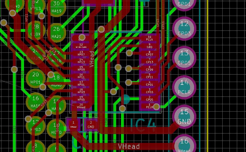
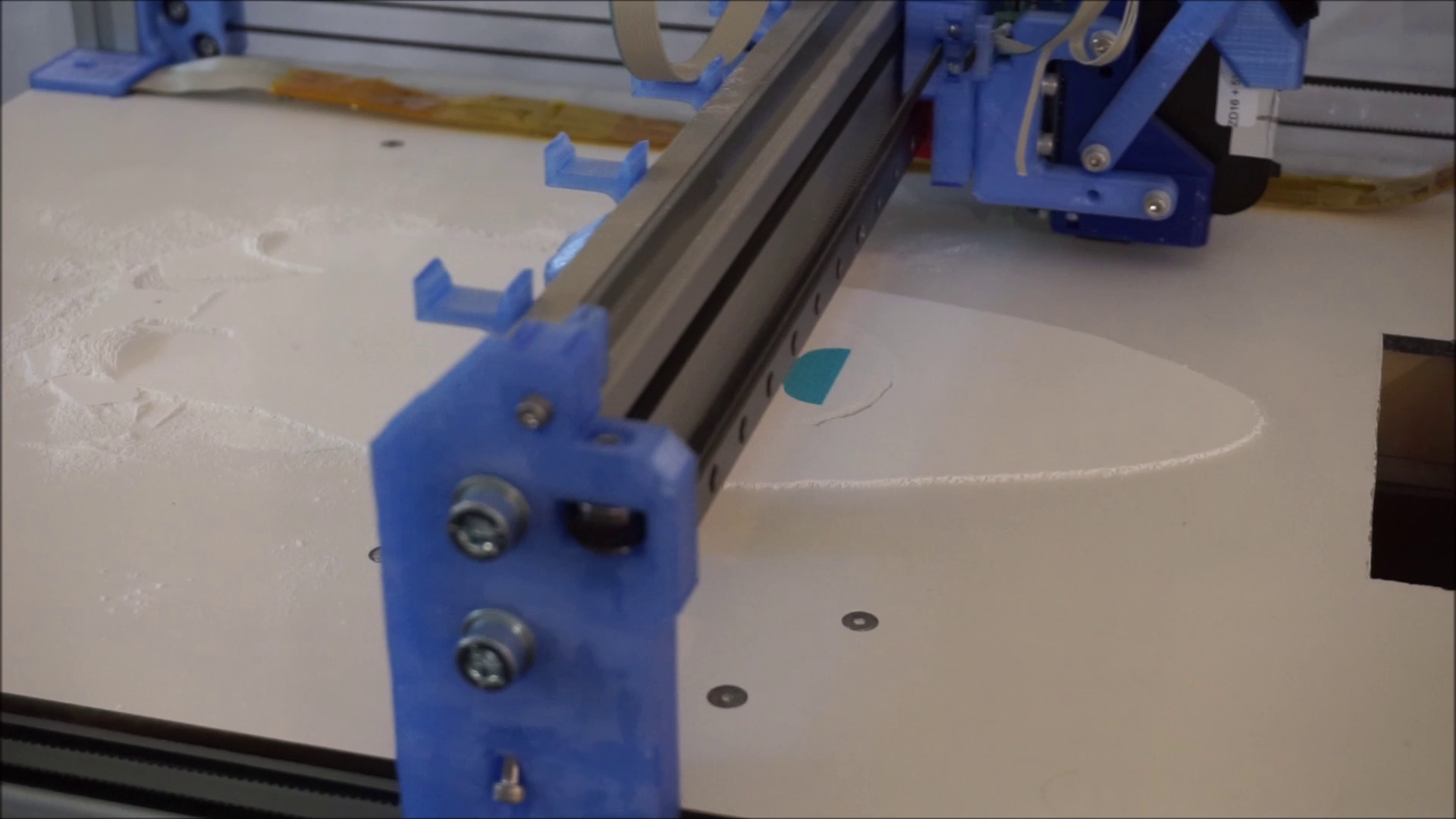
    (Edit 20 minutes later: While designing V3.02 I found an even bigger mistake in the PCB on the TLC driver. It shorts 12V to ground, and several signals directly to ground. It is not in the Gerber files (V3.01 still had V3.00gerber files in it) but it is in all versions of the KiCAD files. The TLC driver has moved 2mm to the side and shorted on everything. I will fix and upload ASAP because this is a real problem. I have no clue how this one got in, but it is quite a bad one. My apologies)


  • Making the spreader go up

    Yvo de Haas12/08/2018 at 11:18 0 comments

    One of the biggest annoyances of Oasis for me has been the spreader. It does an amazing job spreading a new layer, but it has one quite big flaw. It drags powder back.

    This dragging back the powder should not be happening. The pistons lower to move out of the way of the spreader. However, there is quite a bit of overshoot after the piston, and there is powder on either side of the piston as well. This is the powder that is being moved when the gantry moves back.

    The first reason I know it does is because I can see powder being moved when the spreader moves back, the second reason is because there is powder behind the spreader and this heap of powder gets bigger every new layer. The third reason is that in the build piston there is an edge of powder that is moved from the overshoot, back into the build piston. The excess powder in the build piston is actually a serious problem that I do not want.

    See on the left, a heap of powder appearing
    Blue line, roughly where the piston is. Red line, where there excess powder

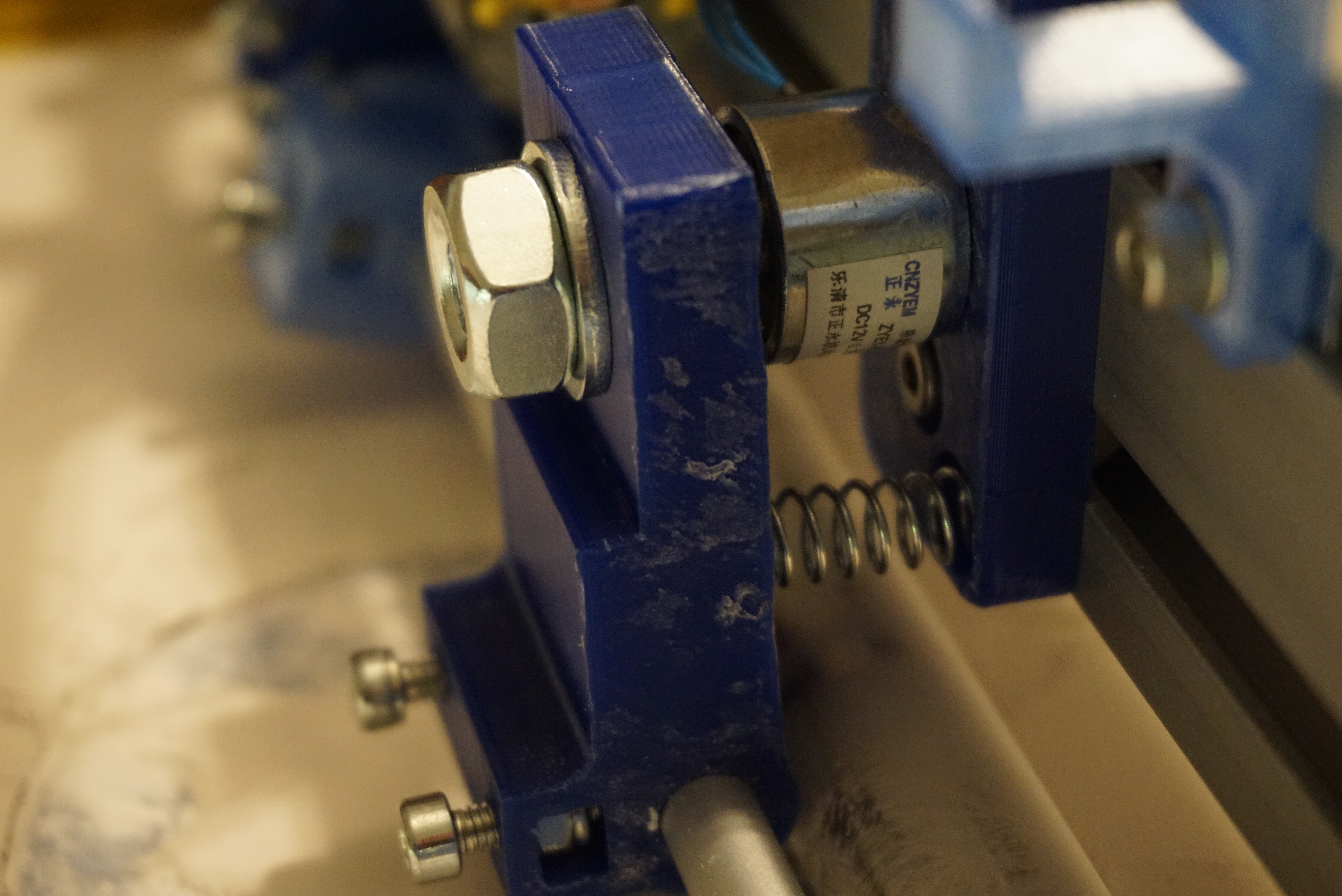
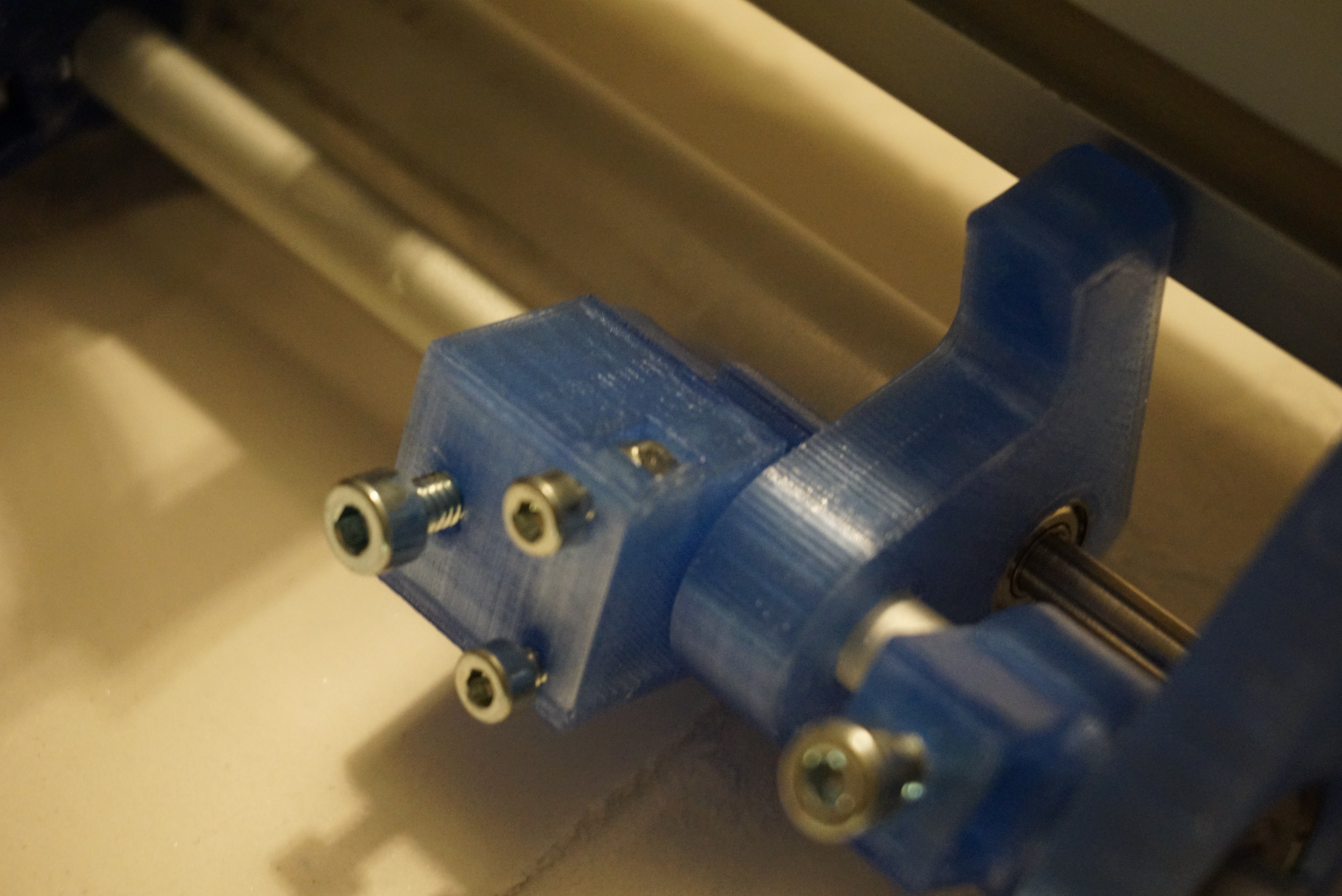
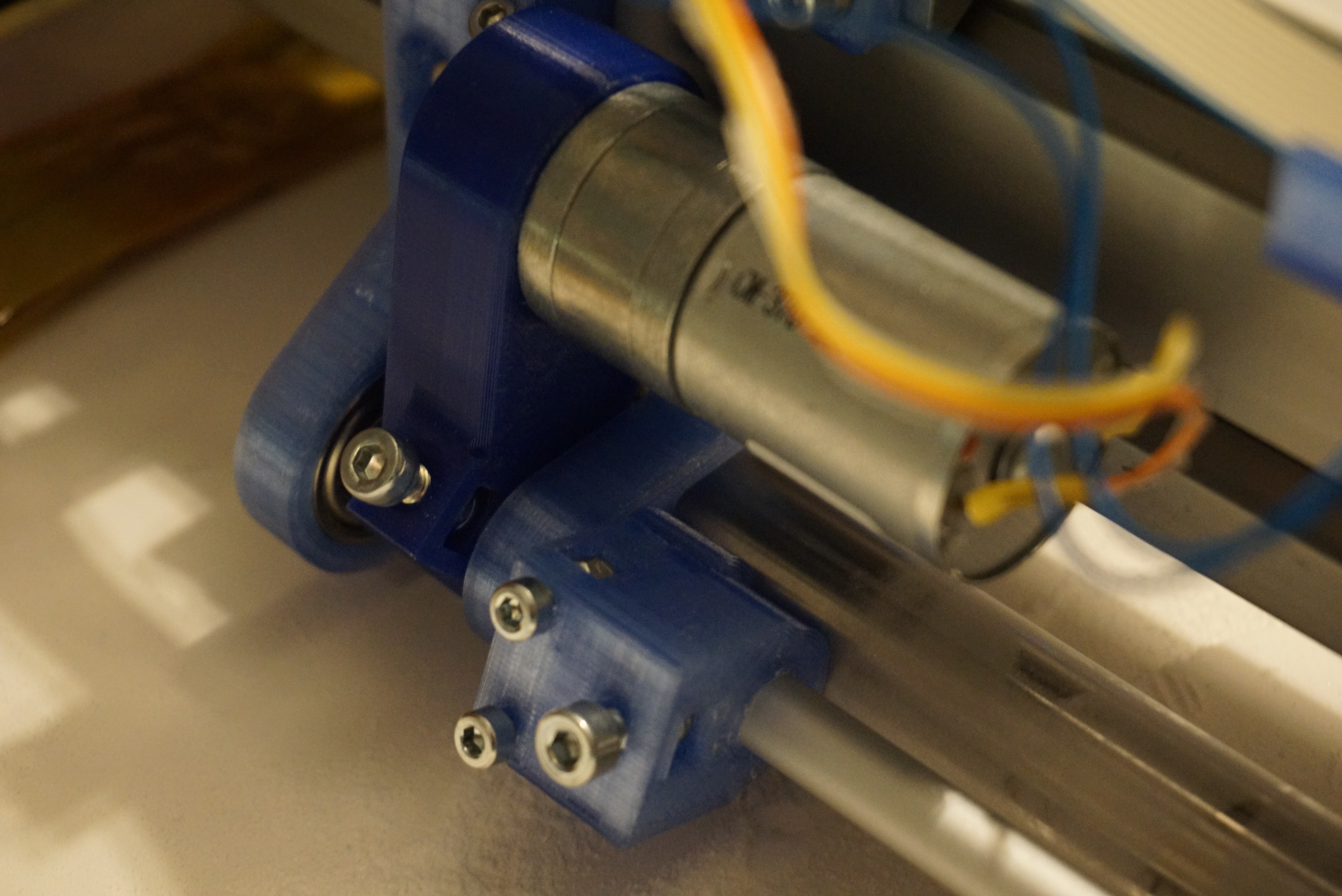
    This problem is cause by the spreader not being perfectly concentric, and some slop in the mechanisms. There are plenty of things I can fix here, but I am going to make the spreader lifting.

    The requirements are simple. When the spreader is on, the roller must be down. When the spreader is off, the roller must be up. The positioning needs to have a high repeat accuracy. It must also not move up under the load of powder.

    I chose a central shaft in 608 bearings to move the spreader on. This way, the spreader moves in it's entirety, and not only left or right. There are plenty of adjustment options I can make, but the old adjustments turned out to be perfectly adequate.

    I run GRBL, so I do not have many options for driving it. Hobby servo's are not an option here, GRBL does not really support them. The only reasonable options that do not require many modifications are solenoids and electromagnets. 12V is one position, 0V is another (with a spring).  I chose electromagnets since I had them (Specifically, this one)


    In the video you can see the spreader moving down (snapping into the electromagnet) when the roller is powered, and springing back up when the power is removed. The up position is a bit springy, but that is OK.

    Because the spreader is now lifting, I will change the software so I can toggle between moving the pistons out of the way or not. For the lifting spreader, I do not need to move the pistons down, saving a second or 2 on every new layer. This software will not be shared instantly, There is more I want to do. The CAD will be uploaded shortly.

    The old spreader works fine for the people who are building Oasis right now. The new one is just a little better at the cost of complexity.

  • Future plans for Oasis

    Yvo de Haas11/05/2018 at 06:44 0 comments

    I have spent the past few months working hard to get Oasis ready before the deadline of the Hackaday Prize. While I am of course a bit sad that I did not win, I knew that I was going against some great projects. Congratulations to all the winners.

    My goal for the past few months has been to get Oasis 'working'. Printing, as good as I can in the time I have. Now that I no longer have any deadlines, I will dial the amount of work I put in Oasis a bit back. This does not mean that I will stop it, not at all. 3DP has been really interesting to me for the past few years, and I still want to make it better, but I need to catch up with other things too, something that I made little time for the past few months.

    While it may take a while, these are the things I hope work on with Oasis for the coming time (not in order):

    Materials

    So far I have been printing with original Zcorp materials. This is not really going to work well on a cheap(ish) and open source DIY powder printer. Zcorp powder and binder is REALLY expensive. I have had my eyes on several recipes since Plan B year ago. I compiled the most notable ones here. Now that I have a machine that is workable, I will finally test some of these recipes.

    My main focus will be ceramics, then gypsum. Other material options such as sand and maybe metal will be for an unplanned future.

    Depowdering

    Cleaning parts is difficult. For Plan B I built a box with gloves and an air pump to clean the parts. While this works surprisingly well. I want to make a better tool using better parts. This will be a negative pressure chamber with better recovery of the powder. I also want more pressure for the cleaning air. Lastly, I hope I can make it somewhat portable.

    Firmware

    Firmware works, sort of. Both the decoding of printing lines and the printing happens in  the main loop. Because of this, I cannot print much faster than 50mm/s right now, while the absolute max should be around 400mm/s. I do not hope to get the maximum speed without FPGA's but I do hope I can reach around 200mm/s without much fuss.

    To get to this speed I hope to offload all of the inkjetting code to interrupts and DMA. If I manage that, I will instantly lose the biggest bottleneck in the code. Set up inkjetting for one burst using interrupts, and letting it trigger through DMA. I might need to update the controller side of the PCB to make it work, but that is a small price to pay for higher speeds in my opinion.

    I also want to add features such as virtual speed and hardware trigger so it can print without an encoder, making it more usable to other people as well.

    Software

    Python I had to learn from scratch. If I would write it again now, I would do a lot of it completely different. And so I probably will. Too many points to mention, but I will make it faster, more stable, more usable, and to fix a problem I still have, make it output Plan B code as well.

    Another thing I want to do in software is make it usable without 3DP. I have yet to think of a way to make a universal inkjet driver for use in other projects, but it is something that I would be really interested in.

    Selling parts

    I have been getting requests for assembled printhead drivers. I ran the numbers for an assembled driver, and I get to the $150-200 range. Right now, with all the software and firmware in a meh state, I really am not comfortable selling it at those prices. I will take effort to make the price go down by redesigning it, and improve the software so it will work for more people and I actually feel comfortable selling it at higher prices.

    Color printing

    I want to find a way to print in full color. There are several options. One is to add a CMY head. HP has ones that are compatible with the HP45 connector. It is narrower however, limiting print speed. I can also make a driver for 5x HP45 printhead. More expensive, but a lot faster. What I decide on will be for later, but I do want to get full color available at some point.

    ... Read more »

  • How to install the HP45 connector

    Yvo de Haas11/02/2018 at 19:05 0 comments

    I sell HP45 connectors on Tindie. In order to prevent the misery that is the connector falling apart, I am writing this guide.

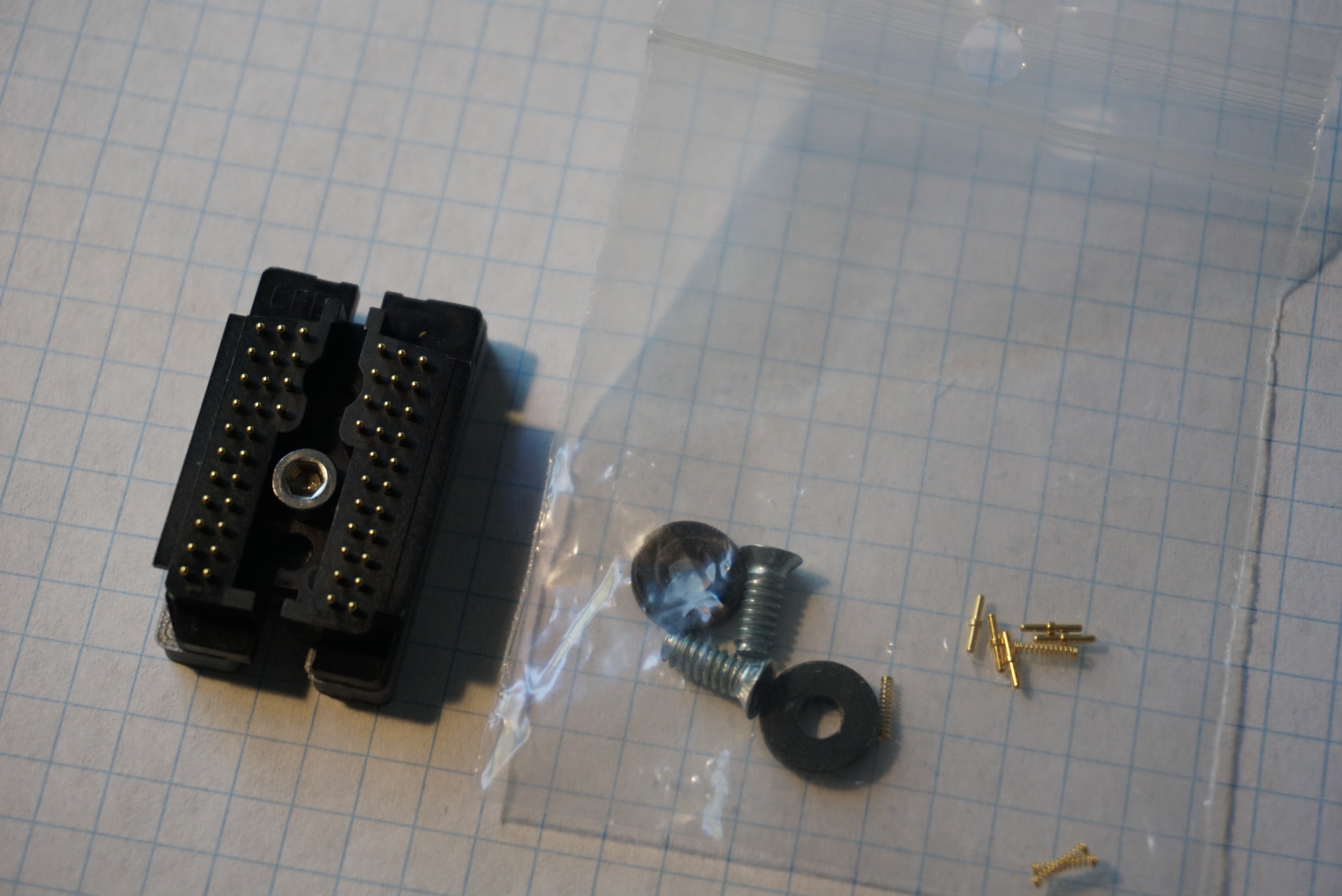
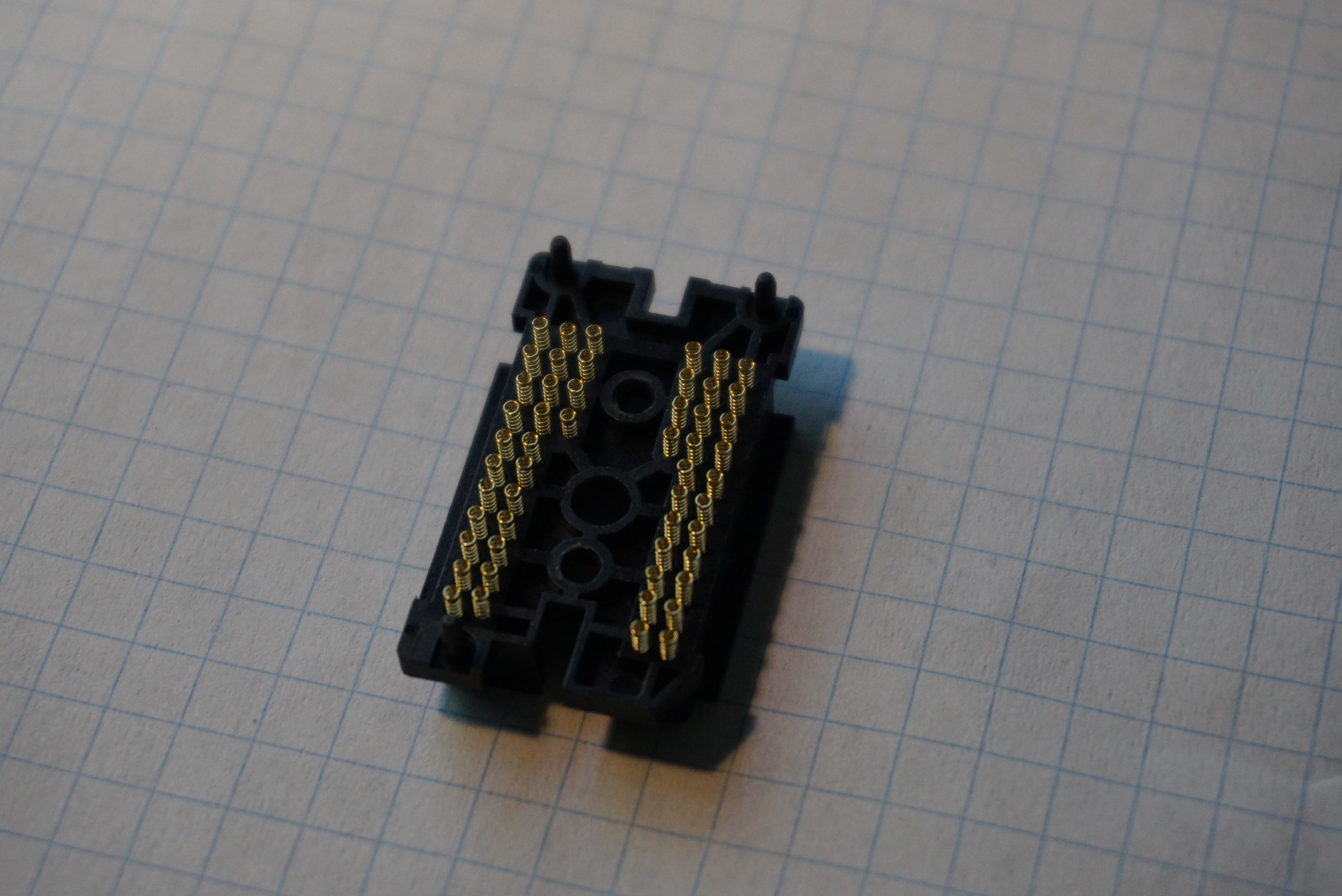
    The kit of the HP45 connector contains several parts:

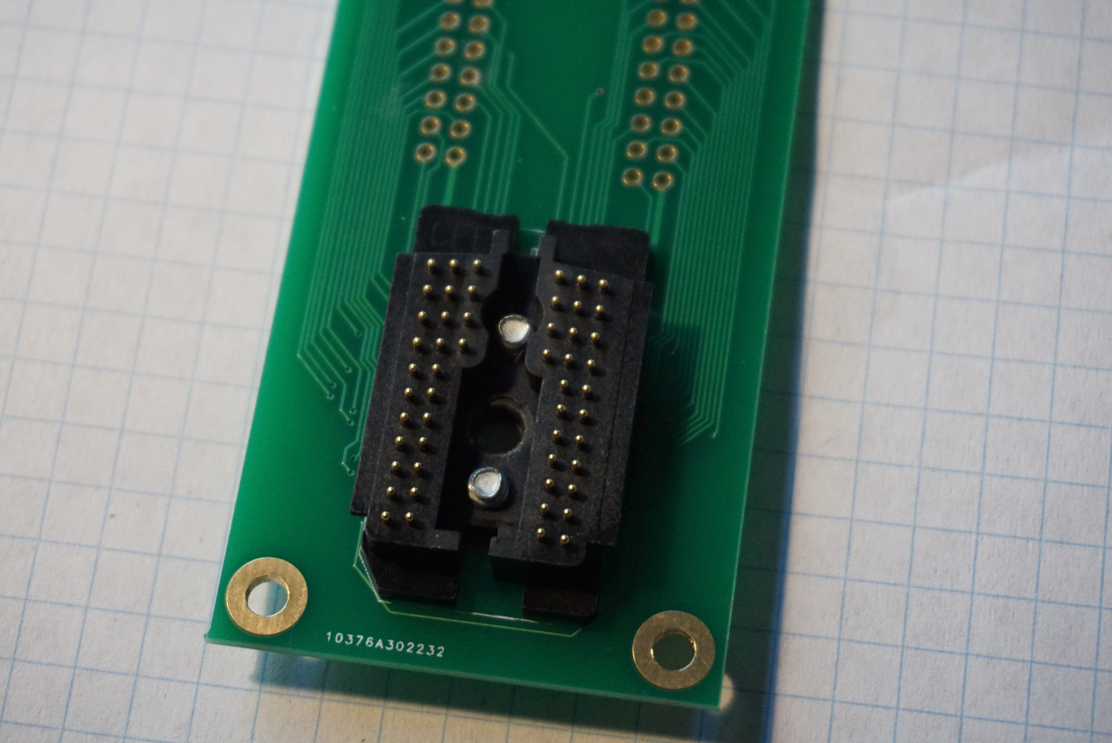
    • 1 Fully assembled, capped HP45 connector;
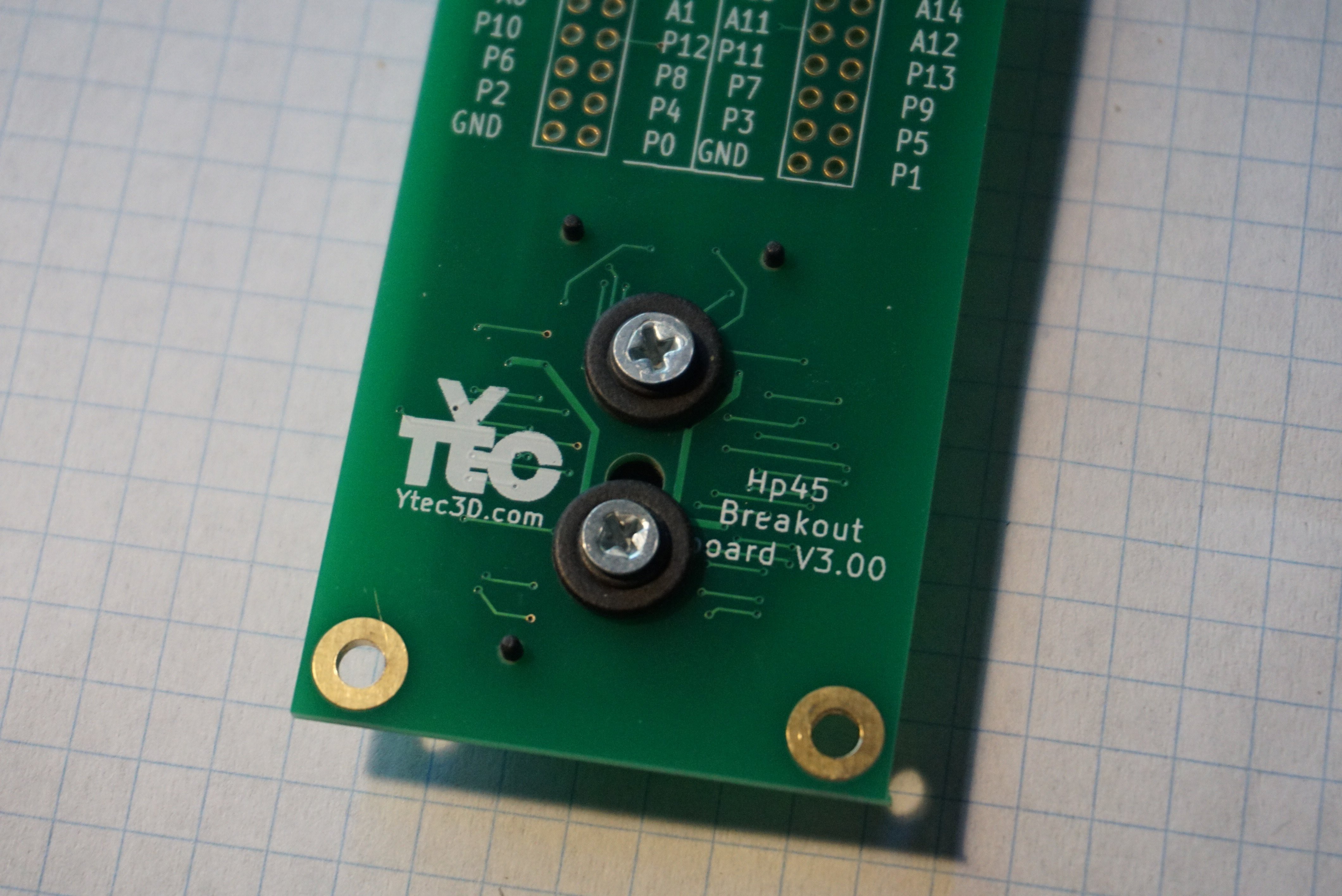
    • 2 #6x3/8 screws to mount the connector
    • 2 Resin washers to get the right depth for the screws
    • 5 Spare pins and springs for if you lose one (or five)

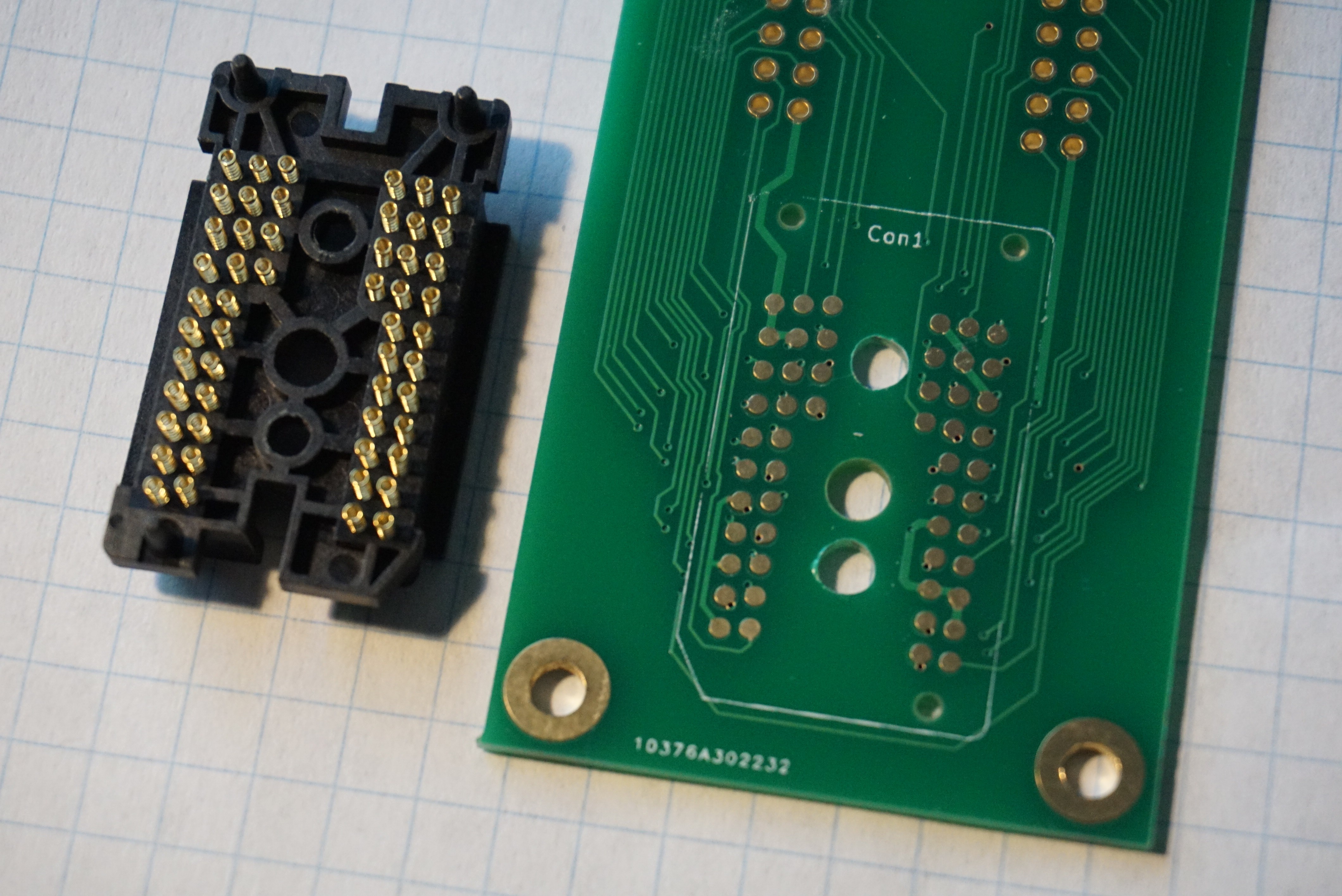
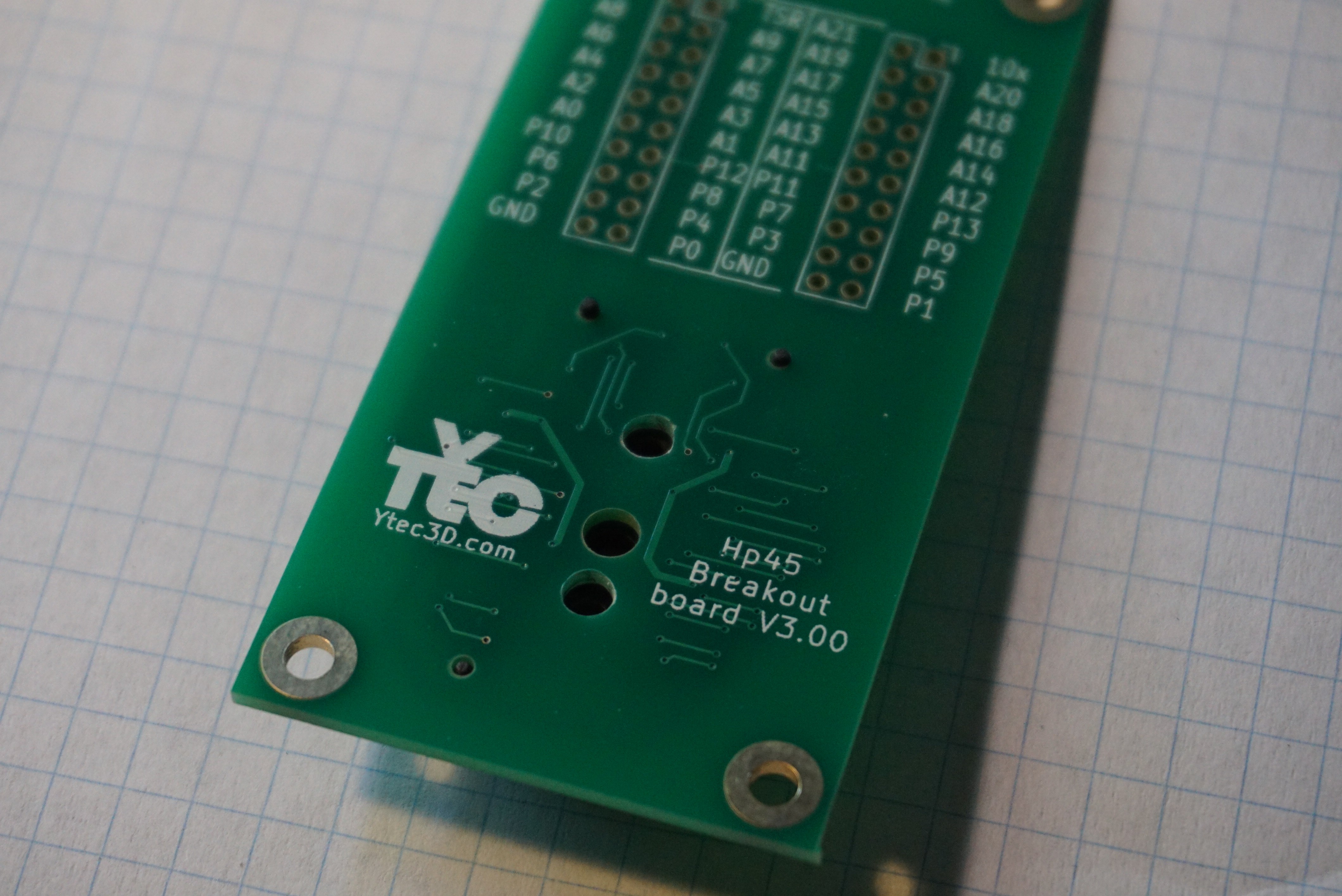
    The footprint of the HP45 connector is in the design files, or as a separate download here. This footprint should be on a PCB of 1.6mm (or thicker) since the 52 springs will push against the PCB. The pads should also be gold plated, since the springs only make direct contact, and are not soldered in place.

    Mounting the connector

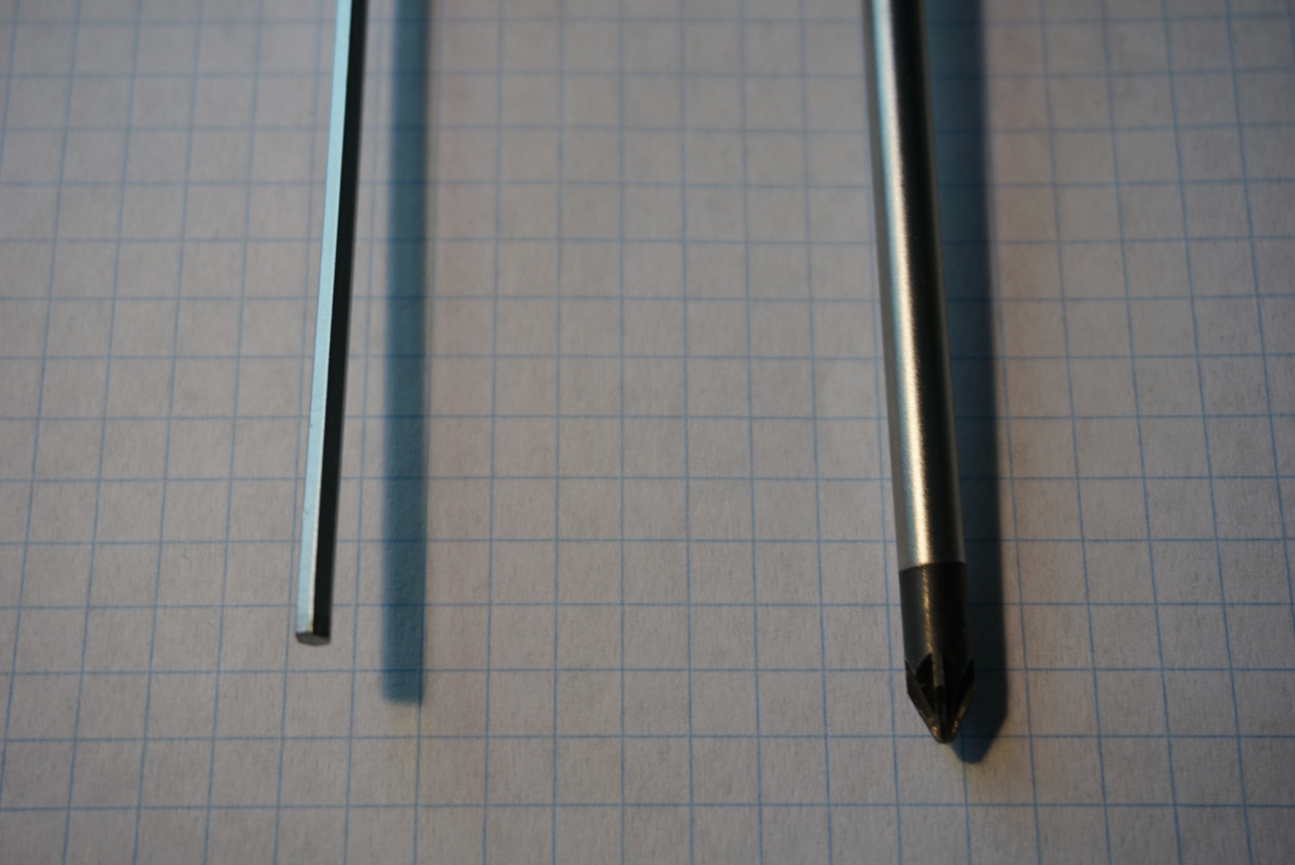
    To mount the HP45 connector you will need a Phillips 1 screwdriver and a 2.5mm Allen wrench.

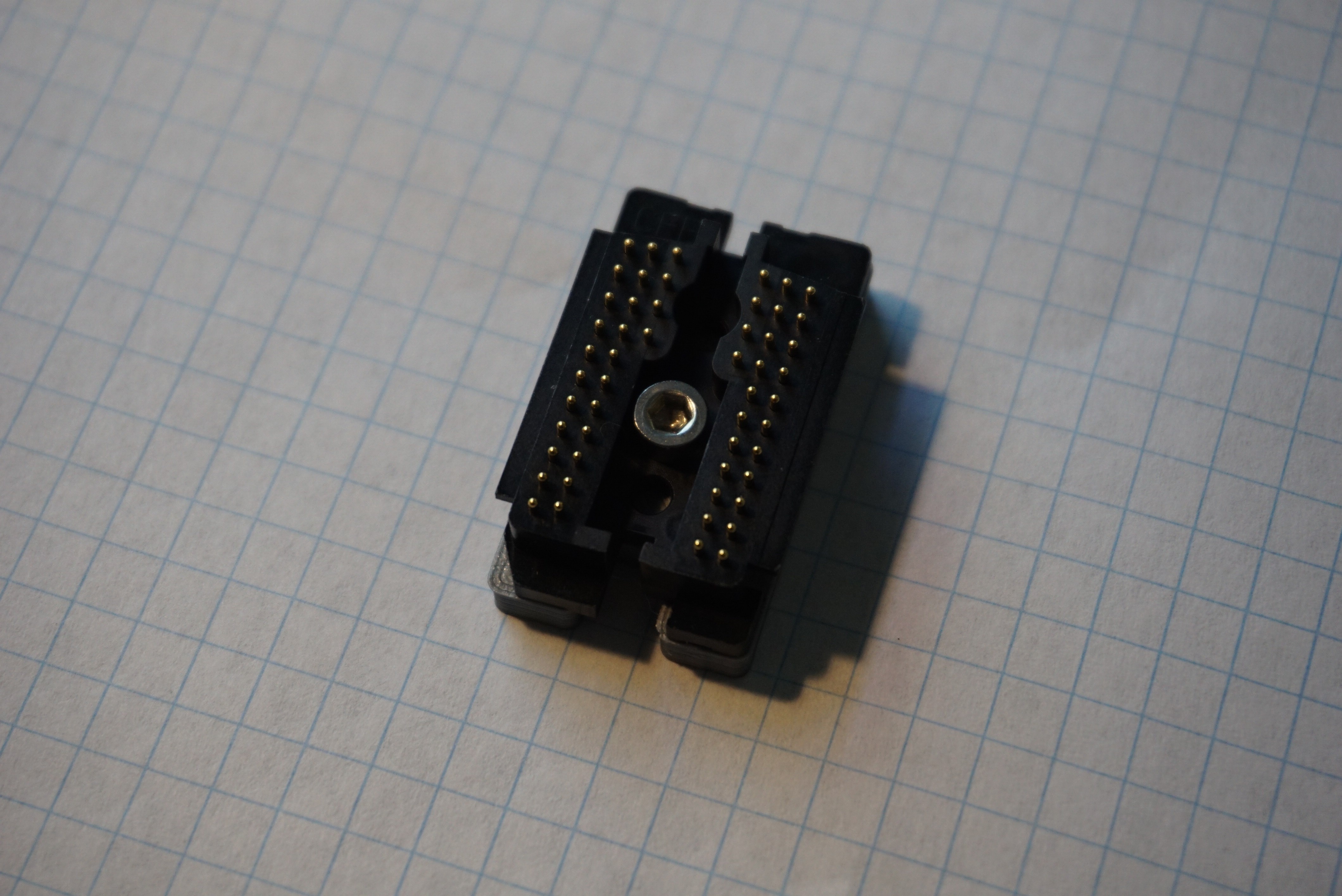
    1. Take the HP45 connector and place it pins facing up, so you see the screw head.
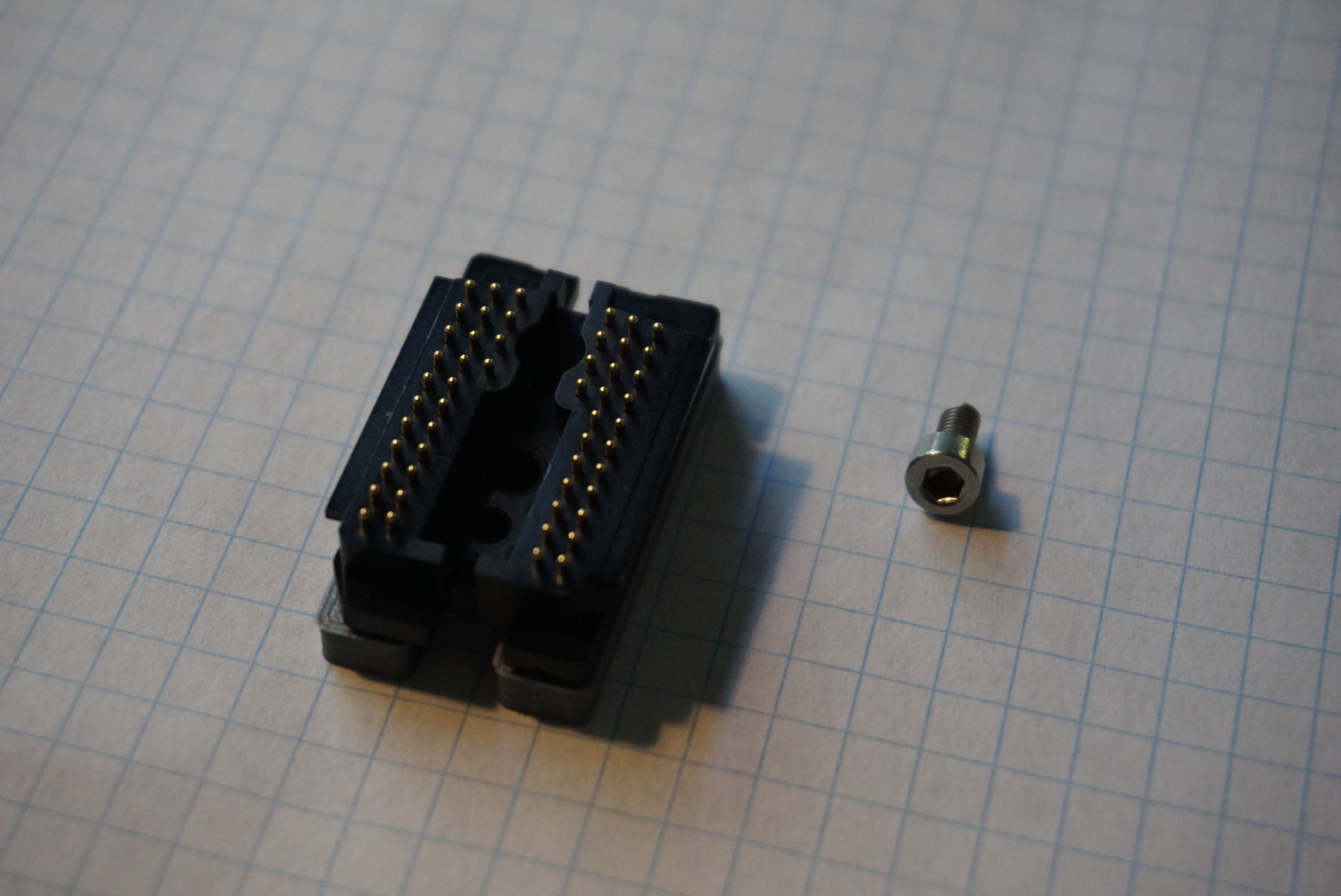
    2. Remove the screw using the 2.5mm Allen wrench (but do NOT lift the connector up).
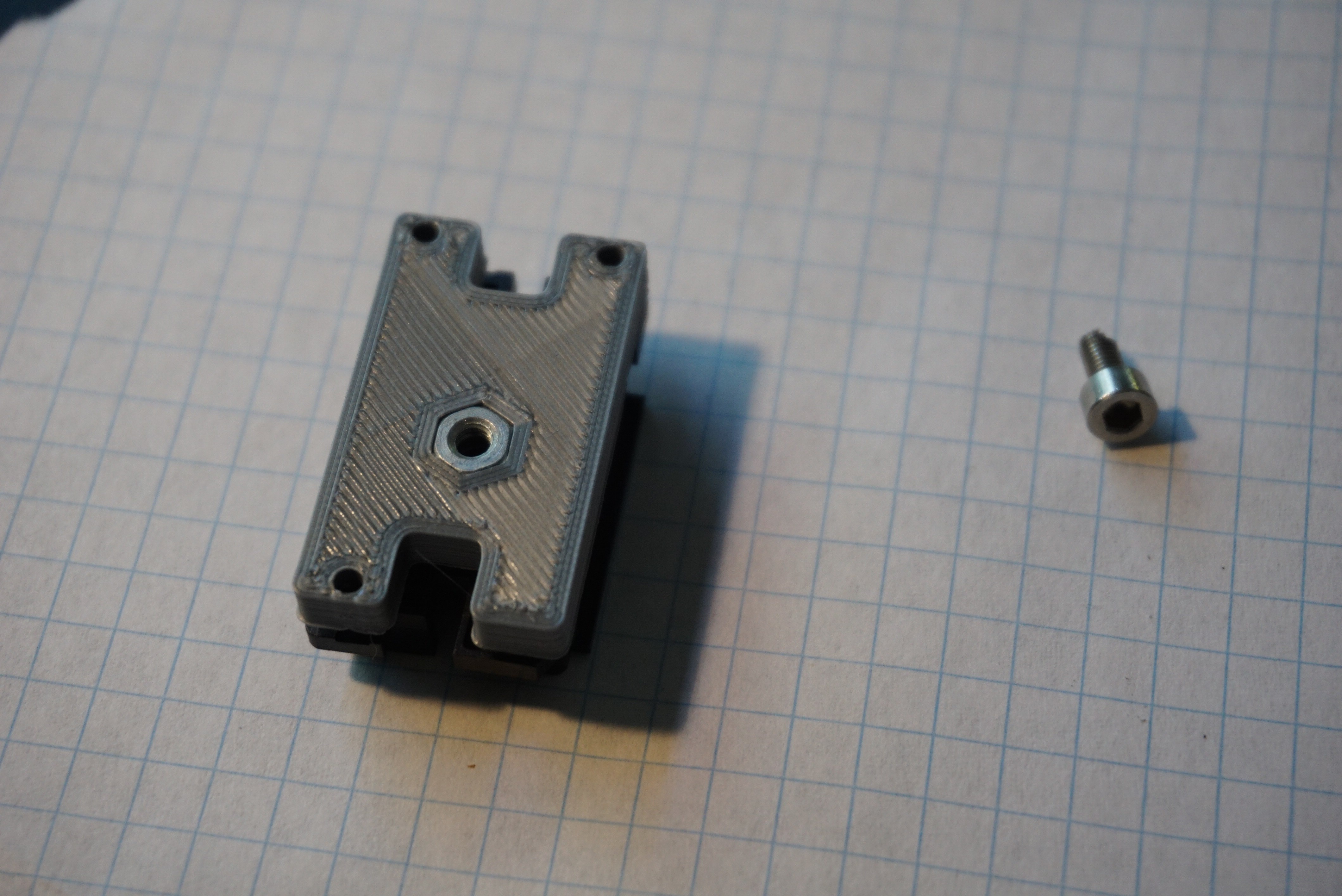
    3. Flip the HP45 connector WHILE holding the back cover on the back.
    4. When the pins are facing down, you can remove the back cover to expose the springs.
    5. Align the PCB with the 3 centering pins, and place the PCB over the connector.
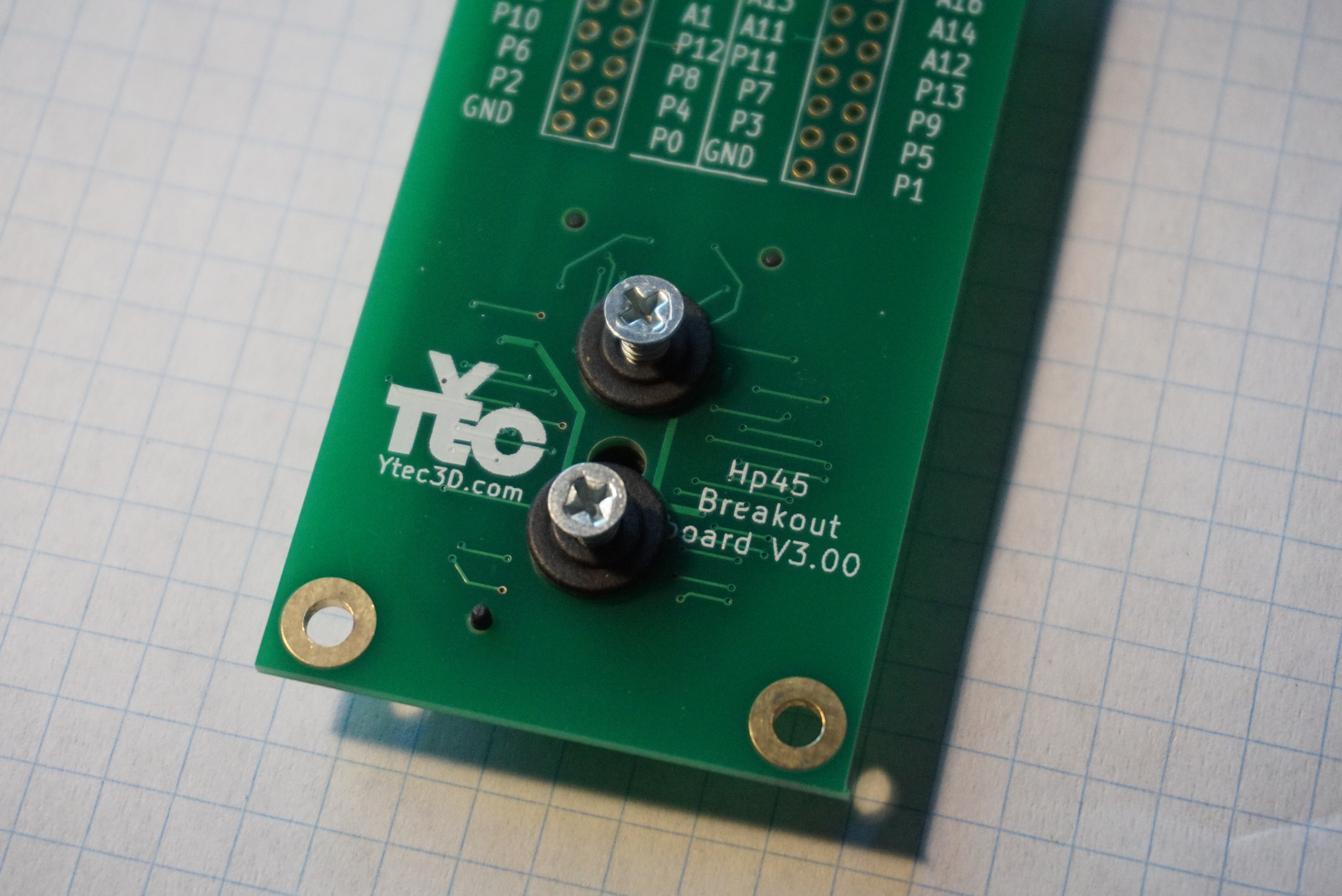
    6. Take the 2 washers and screws and place them in the 2 outer most holes (3.3ish millimeters).
    7. Push on the PCB to make all the springs compress so there is no gap between the PCB and the connector.
    8. Take the Phillips screwdriver and screw the screws into the connector. Do not over tighten, this will strip the threads you make out of the plastic.
    2.5mm Allen wrench and Phillips size 1 screwdriver
    Place connector in this position
    Remove screw
    Flip connector WHILE keeping the cover on the back
    Remove the cover from the back
    Take PCB
    Align holes and place PCB over connector
    Place the 2 washers and 2 screws
    Tighten screws in connector
    Done

    The connector is now ready for use.

  • Can Oasis print a Benchy?

    Yvo de Haas10/24/2018 at 18:49 0 comments

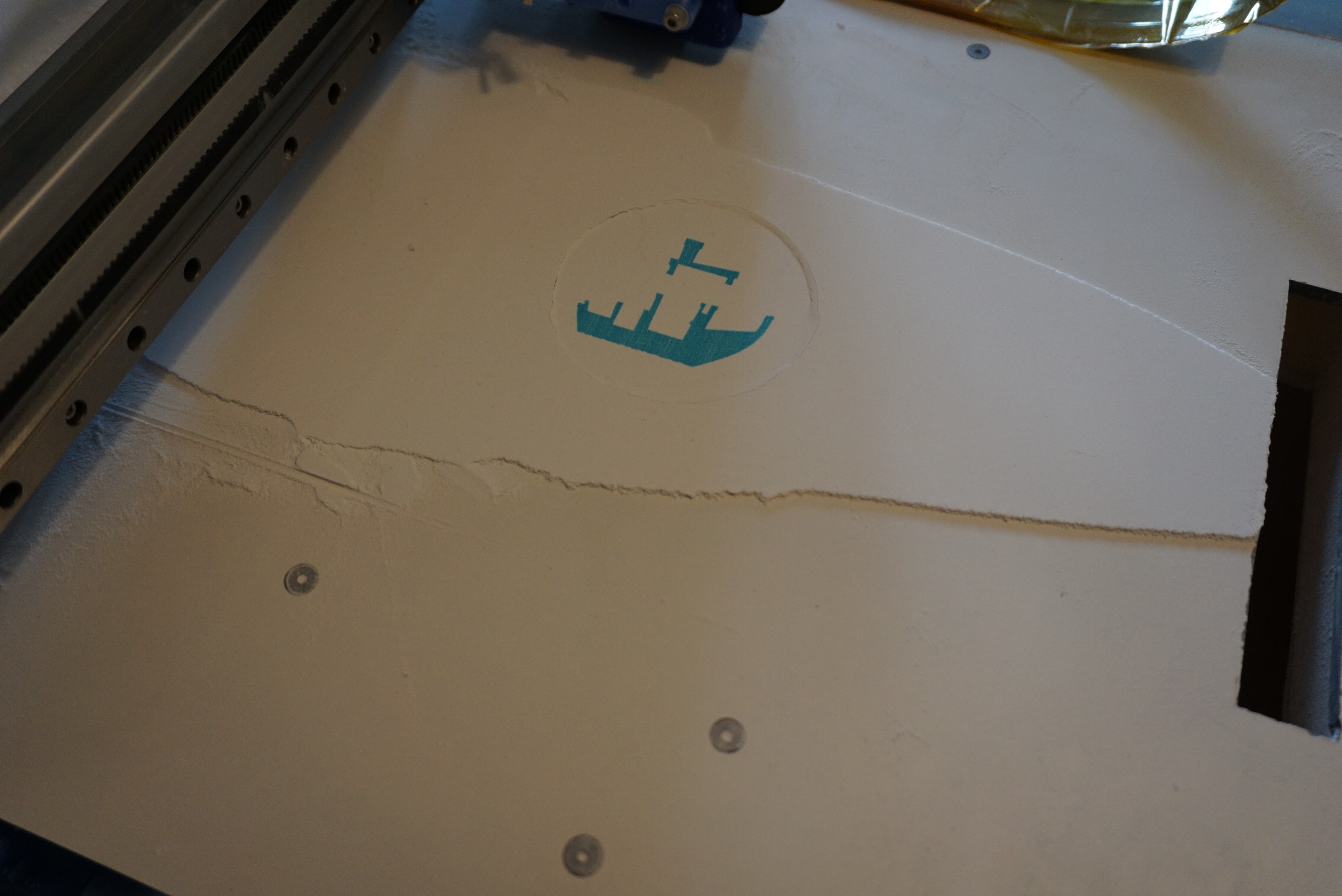
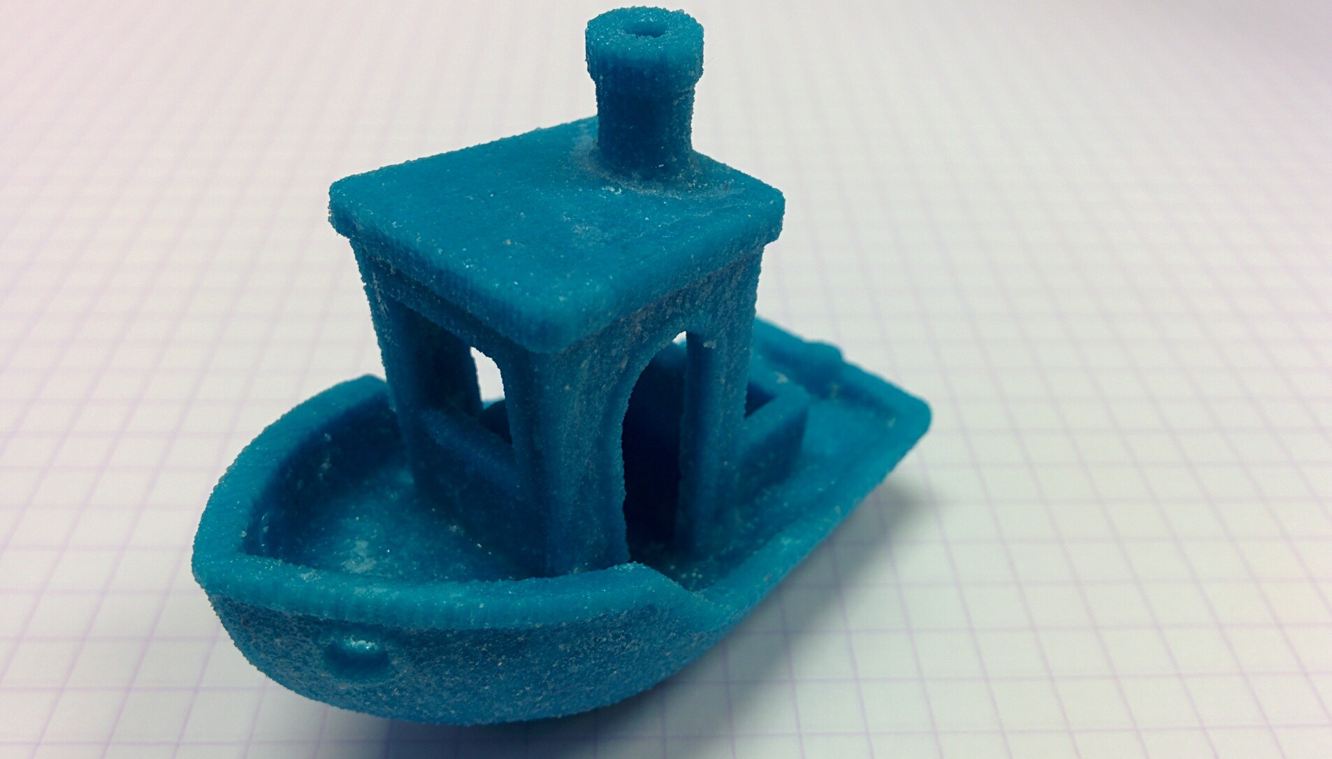
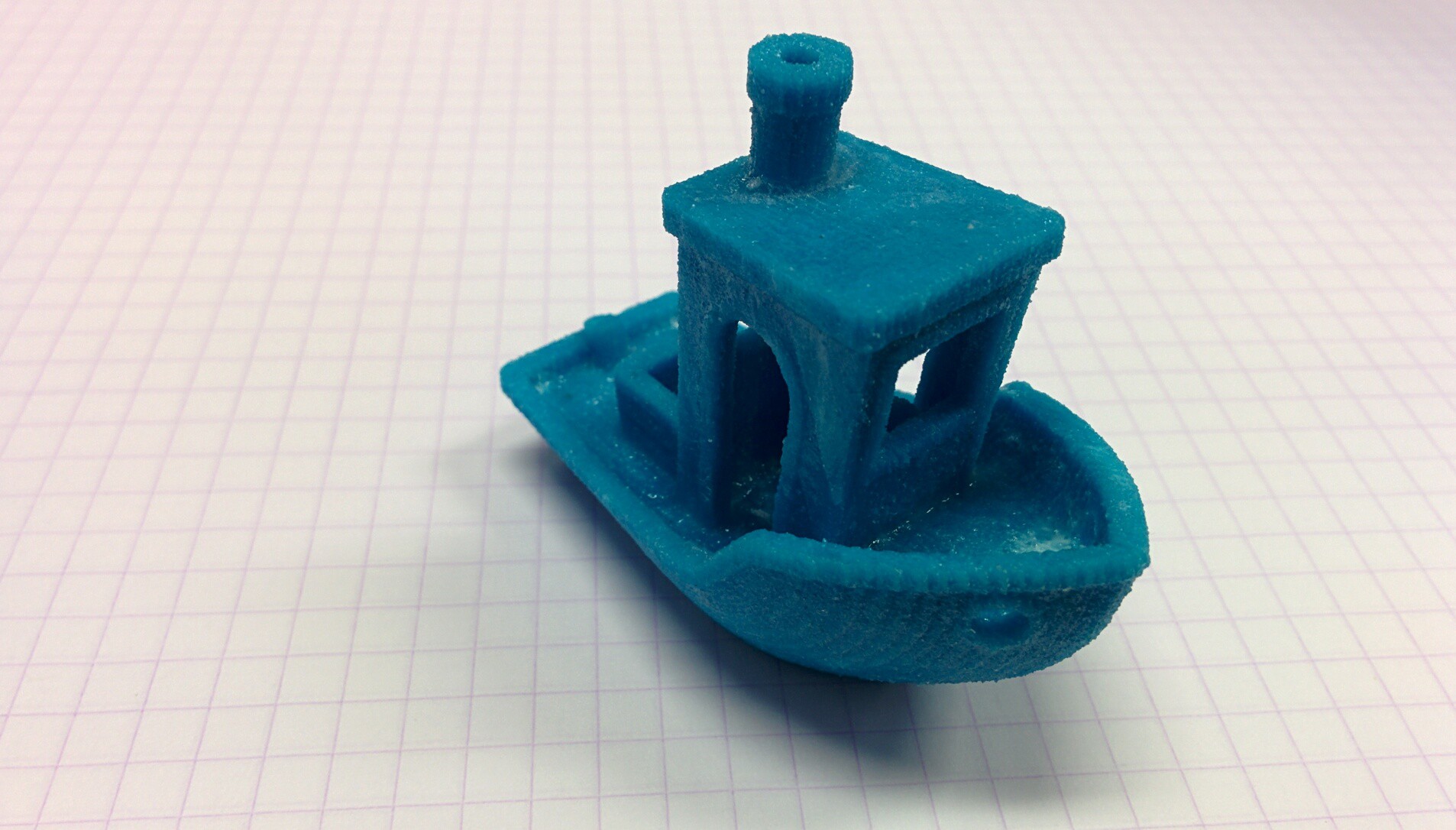
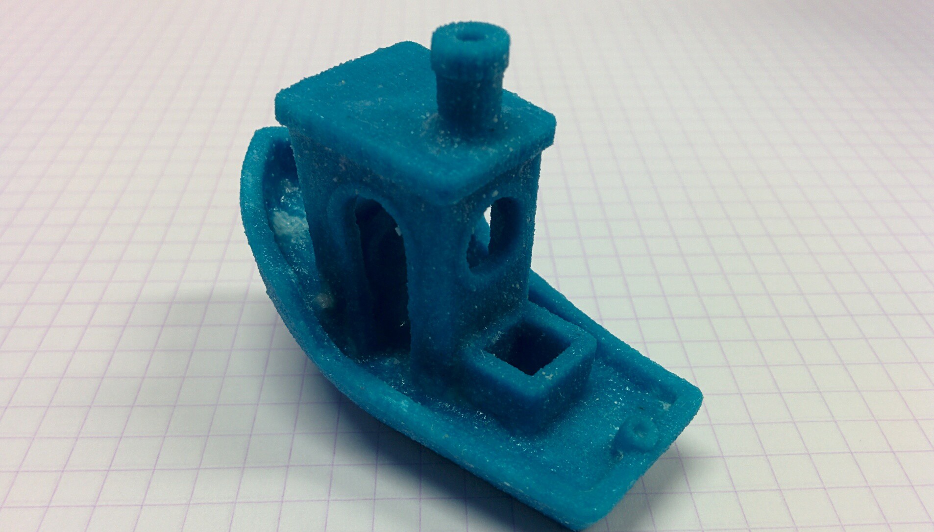
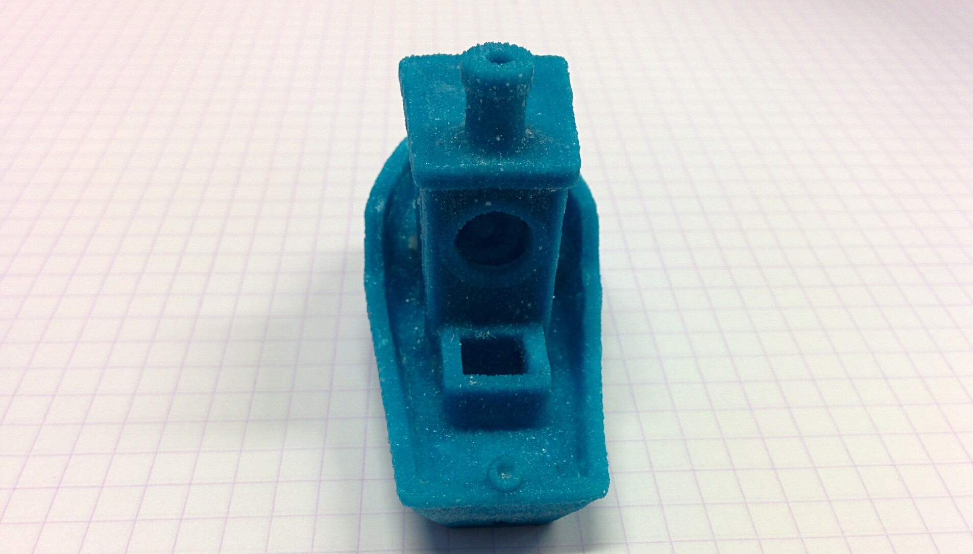
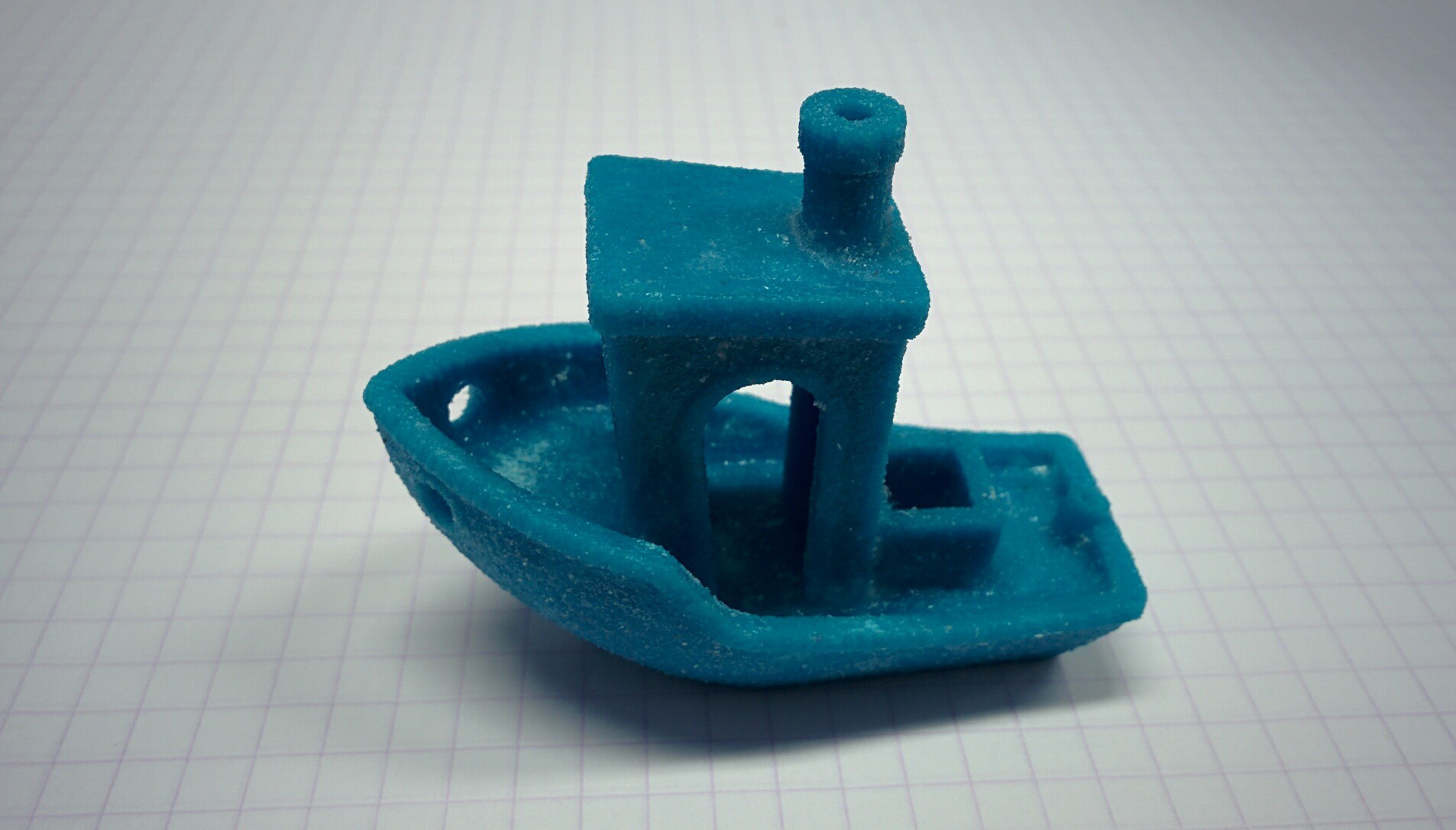
    Yes it can print a Benchy. It took a few tries because Oasis is still a bit finicky and Benchy was quite challenging, even in 3DP, but it looks great.

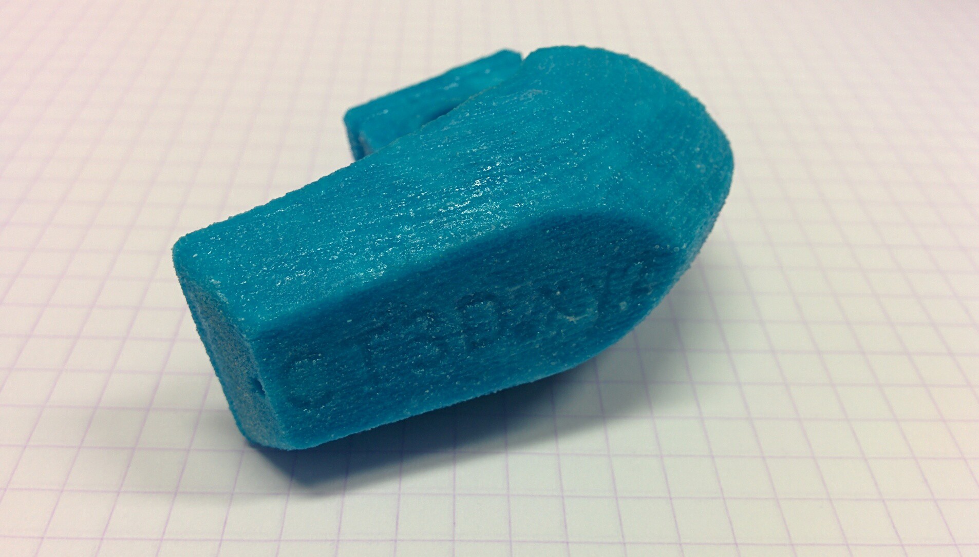
    One fun property of 3DP that is really weird for me to get used to is that I really do not care about orientation, but very much about Z-height. Because of this, I printed Benchy on it's side. It took around an hour to print at layer height 0.2mm. Currently adding a new layer takes 8-10 seconds. Benchy is 30mm'ish wide. This totals 25 minutes of new layers.

    Cleaning and infiltrating it was quite difficult. I did not want to damage it, and my depowdering setup is not perfect yet. I did miss a few small spots, but I got almost all of the powder out.

    The Benchy looks really nice, though it is a bit more rough than an FDM printed part. The text on the back of the boat is not visible, the text on the bottom is. All tiny details are visible. A curious thing I noticed is that the side facing down was a lot more smooth than the side facing up. I suspect I used too much binder, and the binder wicked to the layers below, smoothing out the part. The layers facing up cannot wick into unbound binder, and so stairs are visible here.

    Now that I have printed a decent Benchy, I think I am now legally allowed to call Oasis a real 3D printer.


    (PS. should I be spending a whole log on a Benchy? Probably not, but I don't care, because Benchy)

  • The parts of interest

    Yvo de Haas10/16/2018 at 20:05 0 comments

    Oasis is designed mostly around standard 3D printer parts. However due to some technical challenges with 3DP, there are a few specialty parts I cannot design around. In this log I hope to explain what they are, where I got them, and what alternatives are possible.

    Spreader + motor

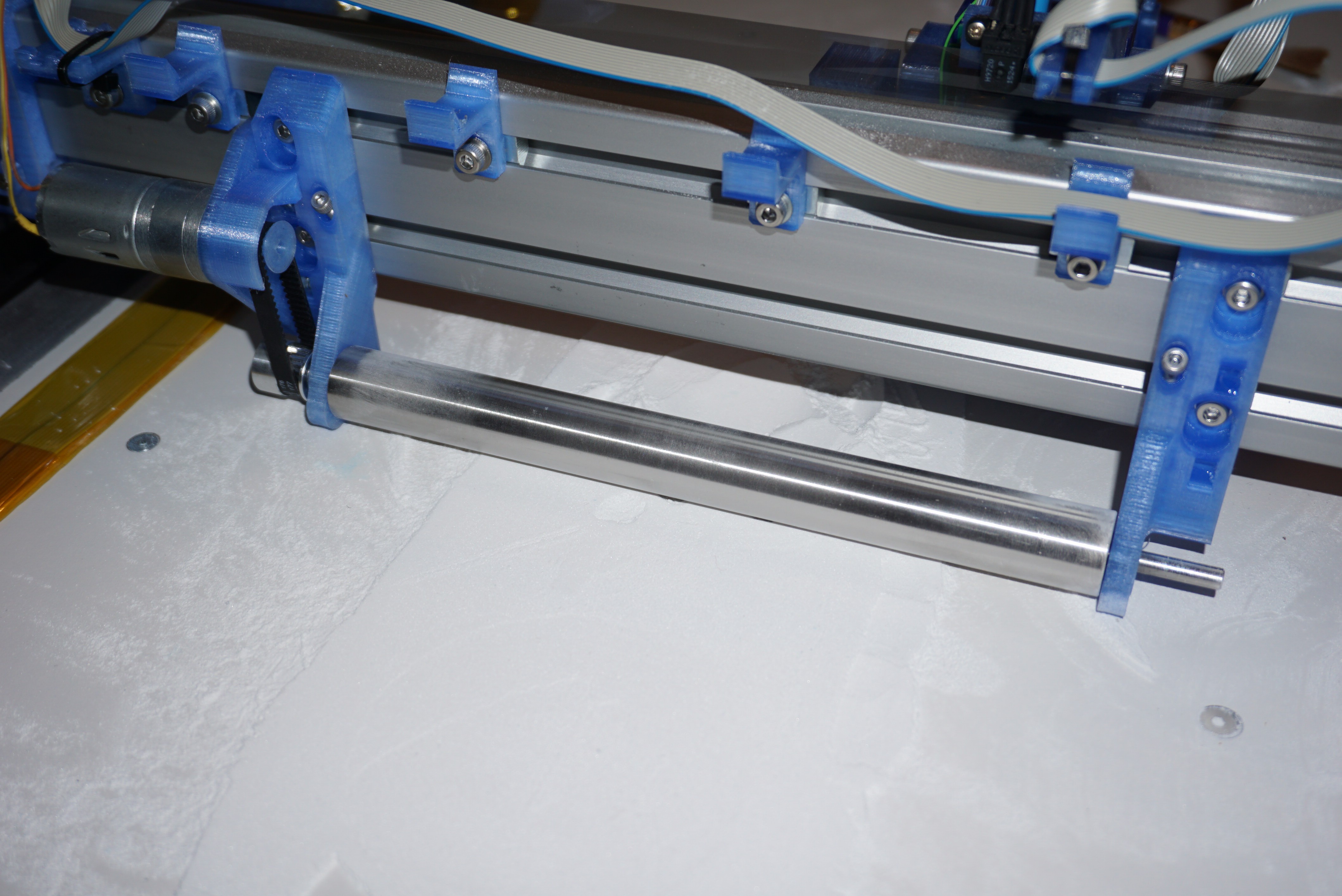
    One of the most important parts of powder printing is the spreader, A round, smooth roller. It is also one of the more difficult parts to get, and possibly the biggest compromise I had to make to ease of getting the parts. In Plan B, first I did without, which did not work. Then I had to jump through a lot of hoops to make one anyway, that worked somewhat. Now I am blessed to work at a company that can order at Misumi. Misumi, is magical. They have everything. The spreader is a standard(ish) part at misumi, 'SSFRHQ20-200-F20-P5-T20-Q5'.

    If you can buy at Misumi, do that. I have included a drawing of the spreader, 'OA-Y20-P13-00'. This is exactly what you buy at Misumi. If you have access to a lathe, you can make the spreader yourself. It does need to be concentric and smooth, but other than that should not be difficult.

    To drive the spreader a motor is required. For this I am using a cheap 25mm gearmotor. I used 300 rpm @ 12V, which seems about right.

    Between the motor and the spreader is a timing belt. I use GT2, and use a closed belt of 120mm long. They are available through the usual internet suspects. Timing pulleys can also be found here if you have trouble finding them. All used pulleys are GT2, 20T, 6mm width. The pulley on the spreader motor is 3D printed for 'pulley not being available' reasons. I advise against printing the other pulleys.

    Encoder

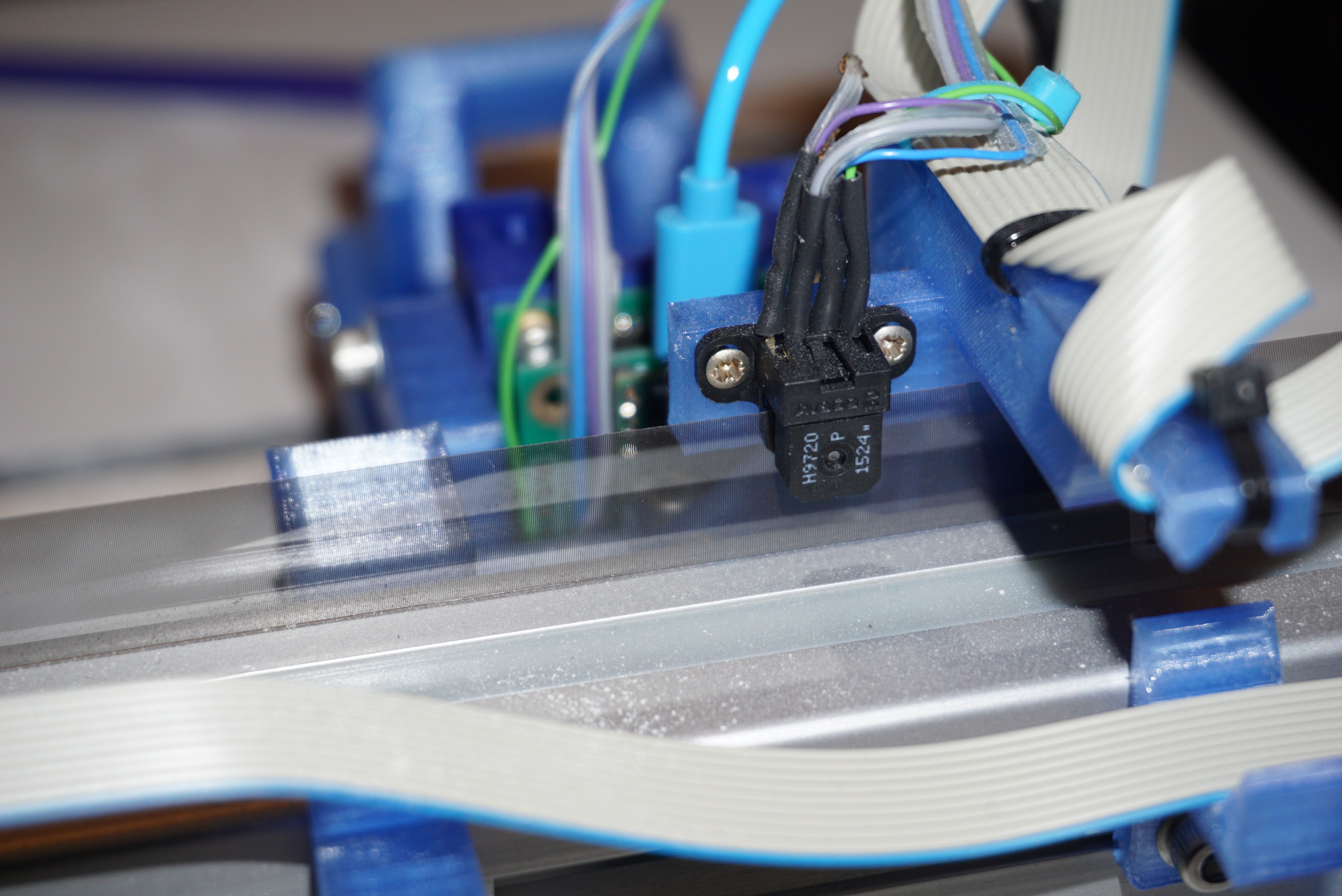
    The printhead and the motion driver are controlled by separate controllers. To synchronize them I use an encoder strip. These things are common in inkjet printers anyway, and are not that hard to get.

    For the actual encoder I use a 'AVAGO HEDS-9740#150', a 150 lines per inch optical encoder head. Most component suppliers list them, but do not have them in stock. Places like ebay do sell them. The tape can also be found on Ebay. you'll need a matching 150 lines per inch tape.

    Bearings

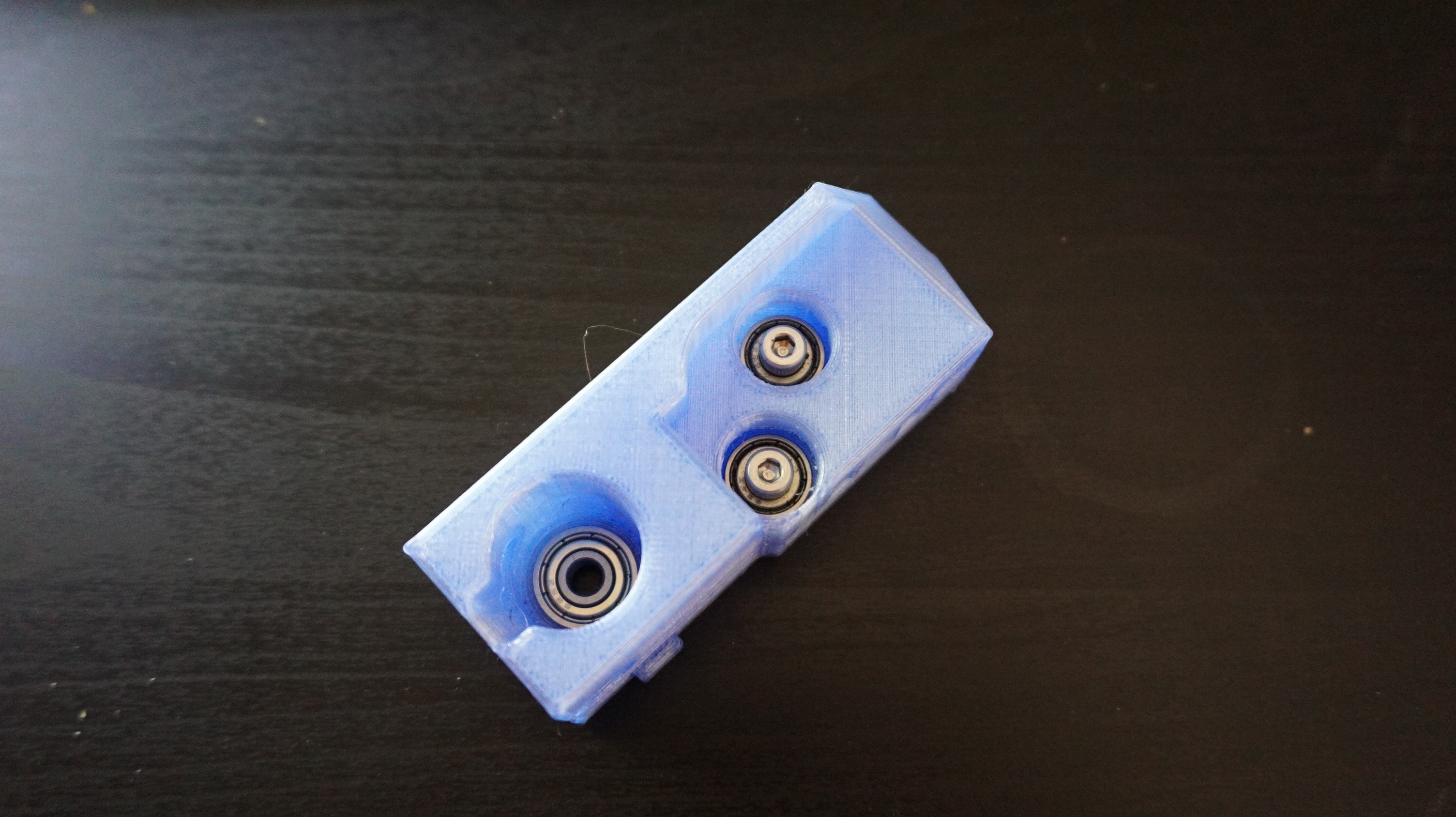
    Oasis uses mostly standard 3D printer bearings (608, 624, 625, preferably ZZ, LM8UU). However, on some places special bearings are needed. The spreader takes 685-ZZ (685-2Z) bearings. I cannot easily provide a link, but ebay has them in bulk.

    Aluminium extrusion

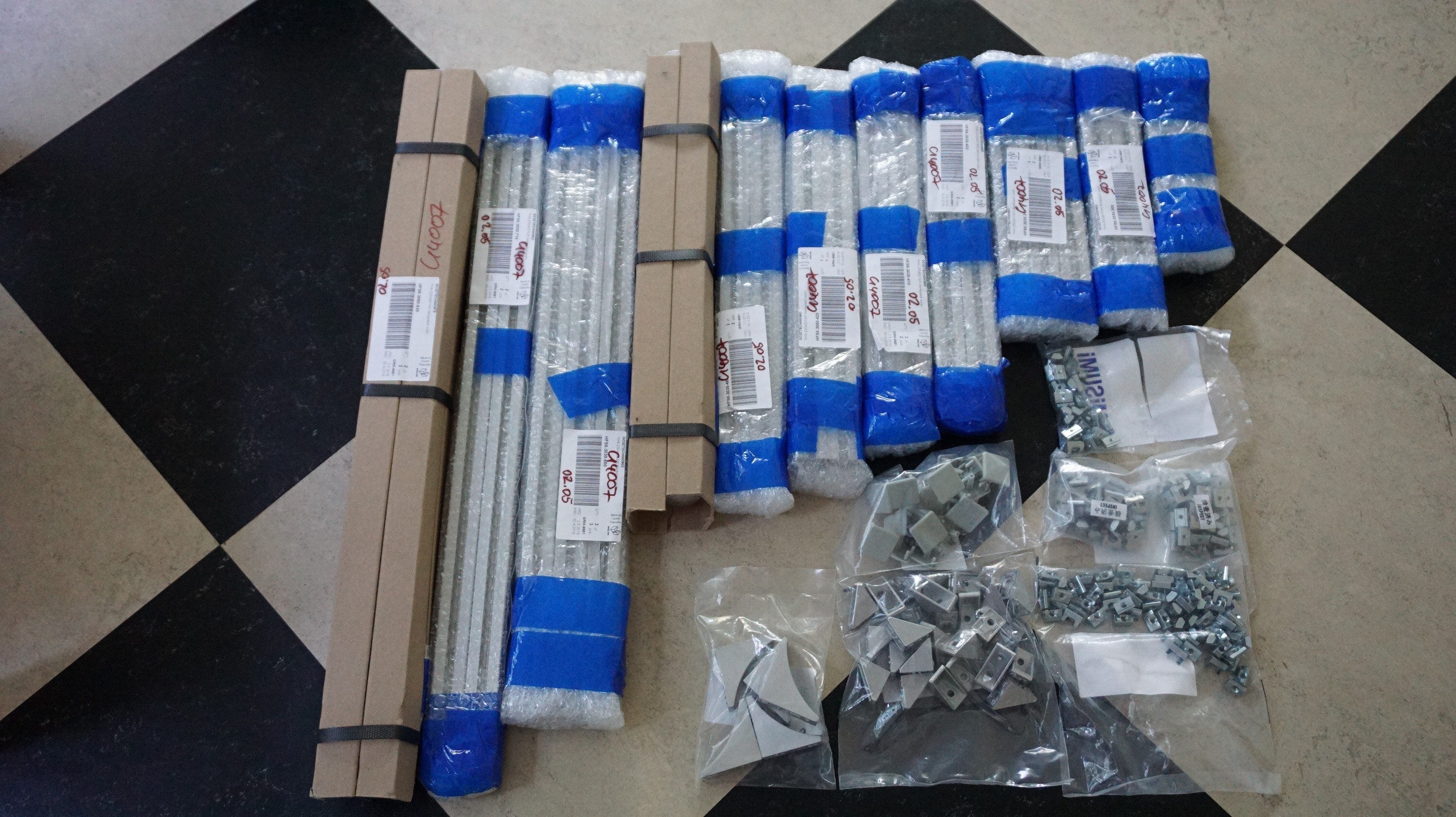
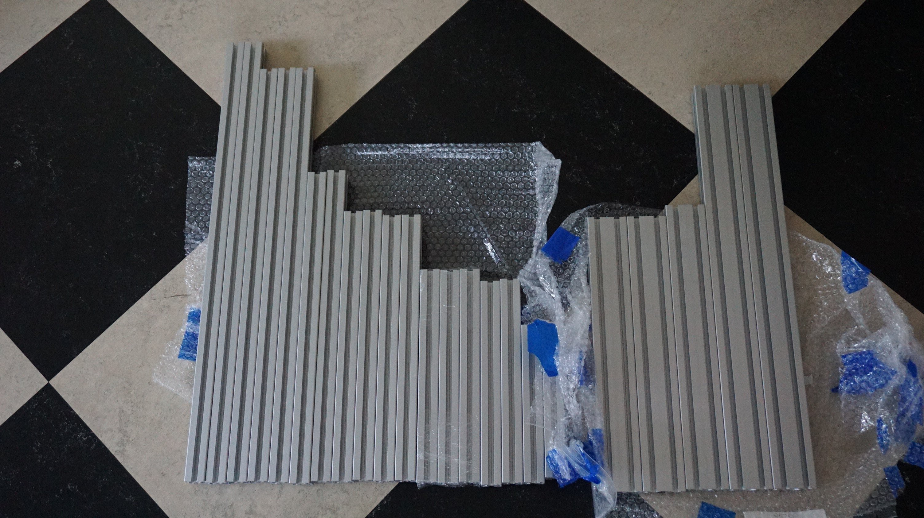
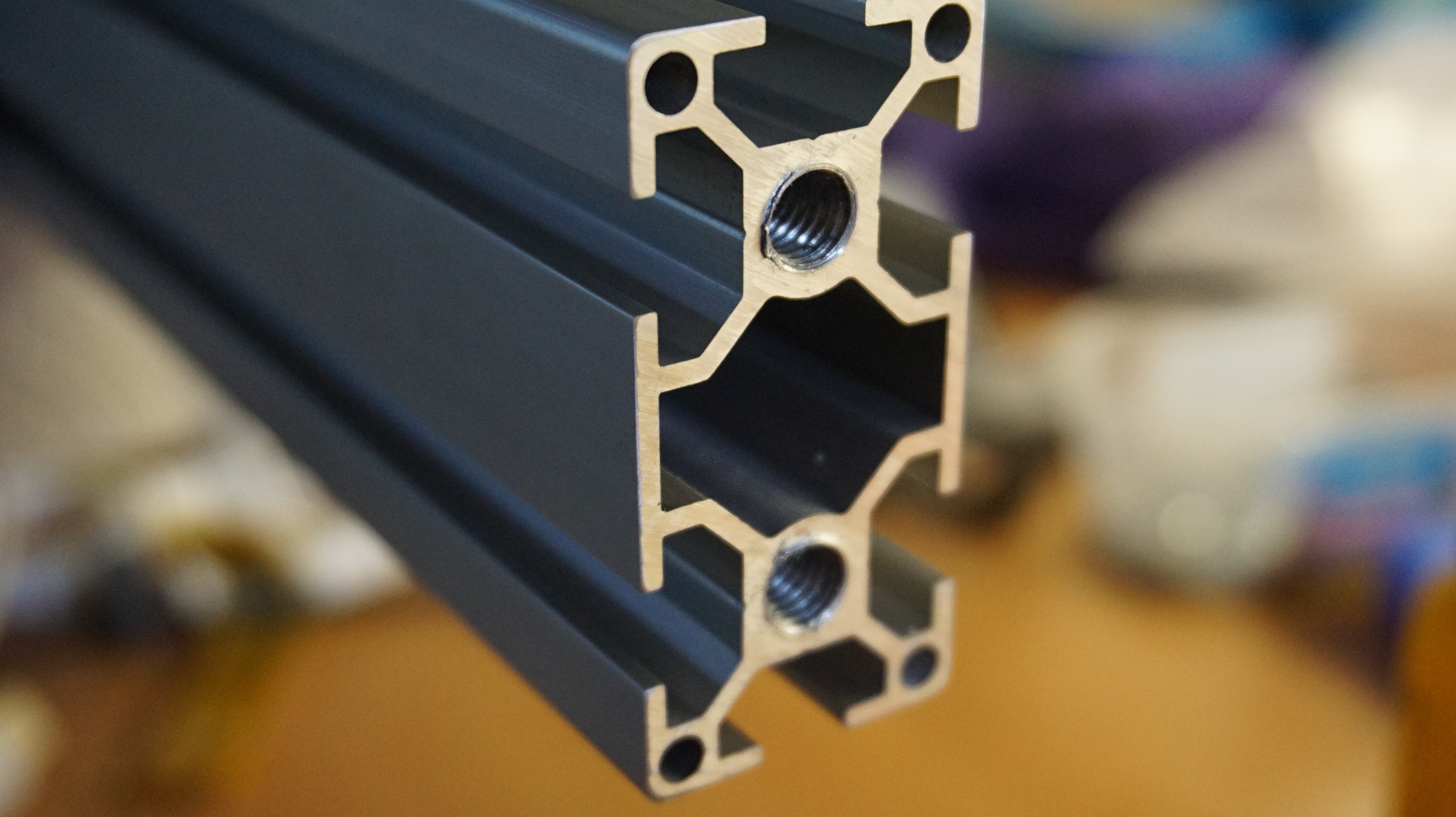
    Oasis is built around aluminium extrusion profile. 2 types of profiles are used. 30x30 and 30x60. There is not much to the profiles. They need to be 30mm, have a groove of 8mm, and the hole in the middle of the profile needs to be able to take an M8 thread. Not all profiles will need M8, but some do. You'll also need 30x30 angles, and 60x60 (2x30 long) angles. The exact type of nut you'll use is unimportant, but I prefer profile nuts that can be inserted after assembly. 

    I bought mine at Misumi because I was already ordering. I suggest finding a supplier near you. In the BOM, the Misumi name is given, but the number in the order number is the required length. You can use that to cut your profiles.

    An example of the used profile. Bear in mind that not all holes need to be tapped M8.

  • A video is there

    Yvo de Haas10/09/2018 at 18:44 0 comments

    There now is a video of Oasis


    I will not add much more to this log, since I spent the last week making this (^) video. I can now work on finishing the file packages and instructions for other people to be capable of making this printer.

    One last thing that will be clarified in the previous log: https://www.tindie.com/products/Dragonator/hp45-printhead-connector/. I now sell the HP45 connector on Tindie.

    Previous log: https://hackaday.io/project/86954-oasis-3dp/log/153322-some-info-on-interfacing-with-the-hp45

    Because logs are ordered by when the first draft was made, not when it was published, putting my 2 weeks ago started log behind this one.

  • The color of the day: Blue

    Yvo de Haas09/27/2018 at 19:03 0 comments

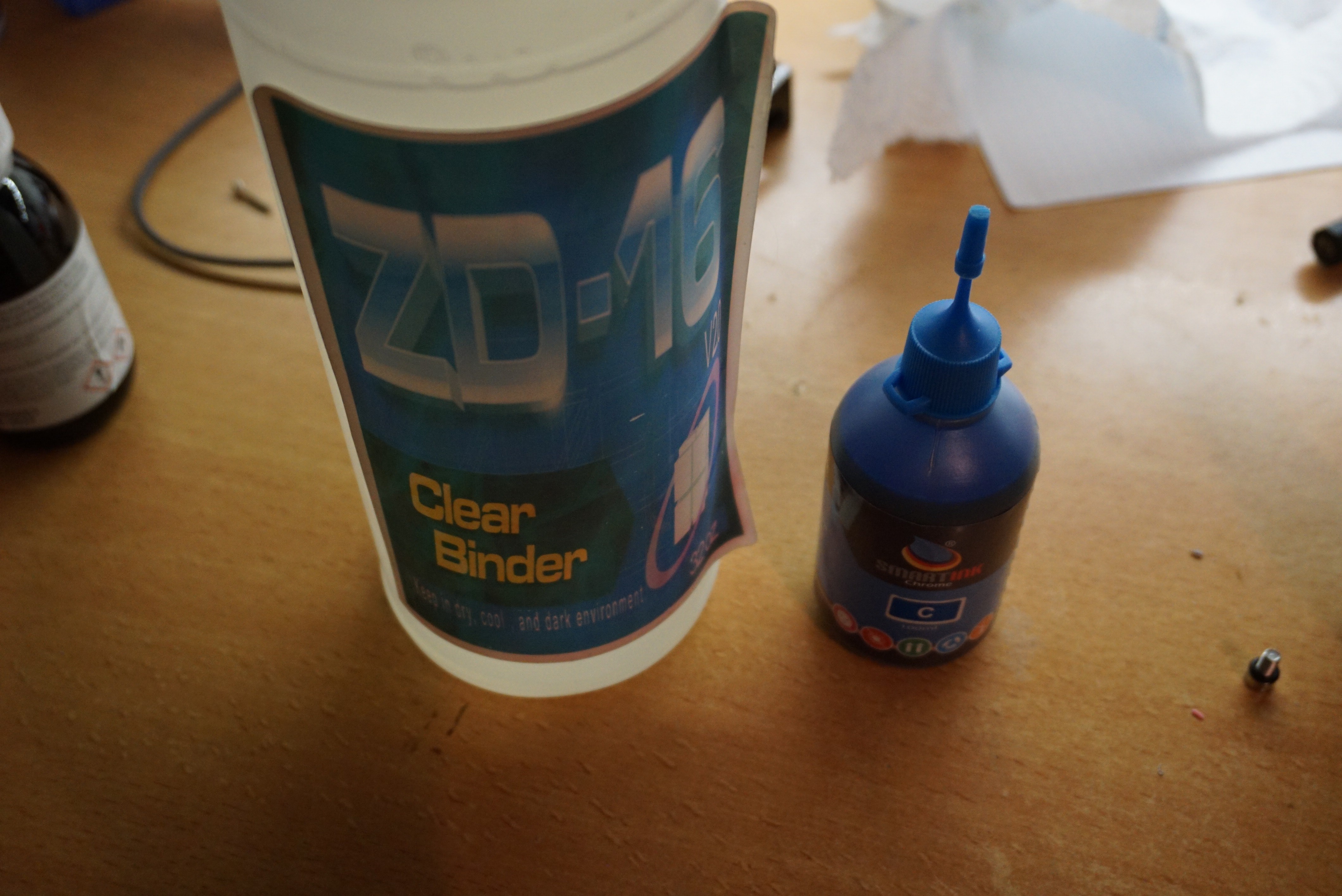
    I refilled my printhead with actual Zcorp binder. I got this stuff from a friend of mine a while ago, and it will allow me to get a bit of a baseline before I start messing with my own binders and powders.

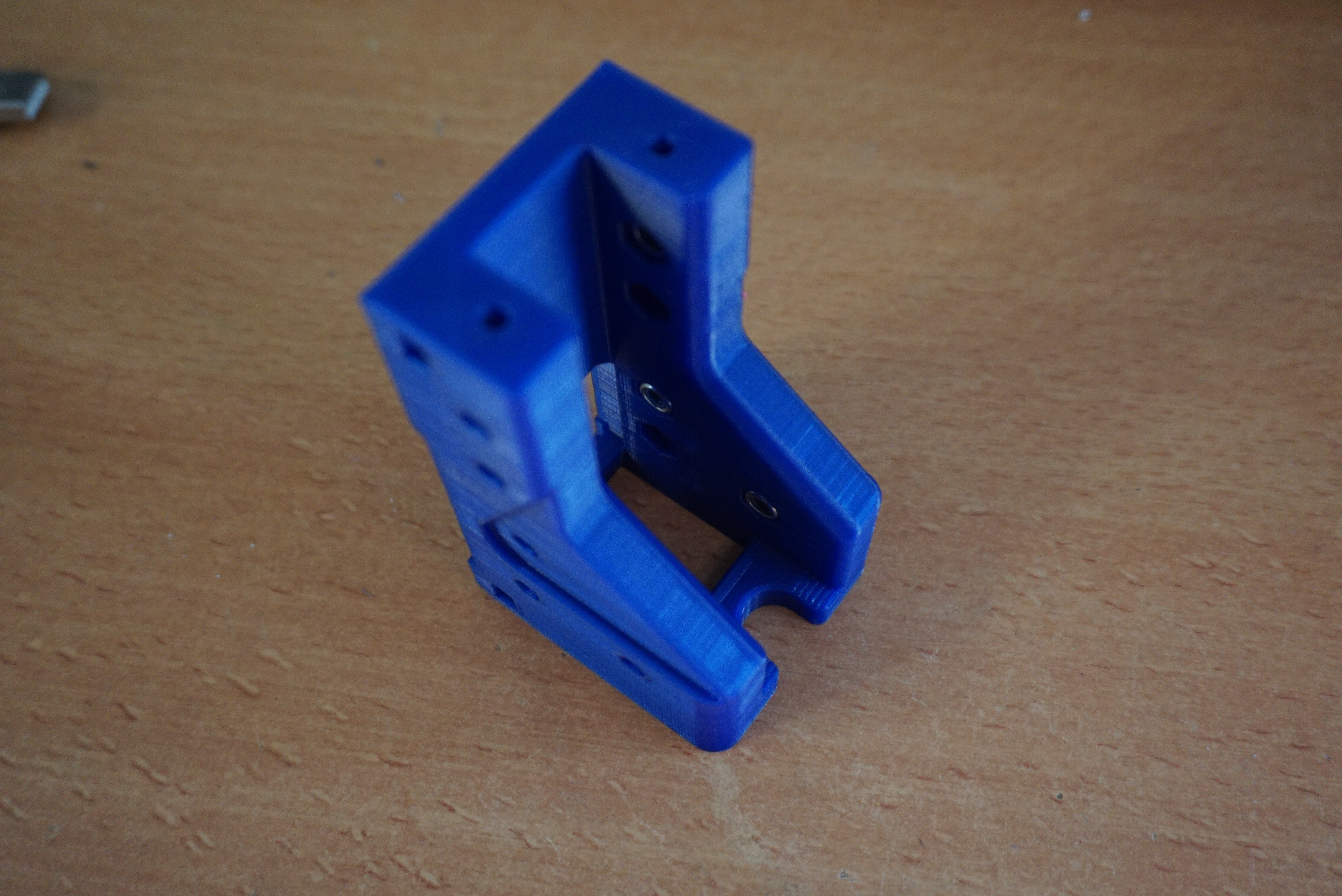
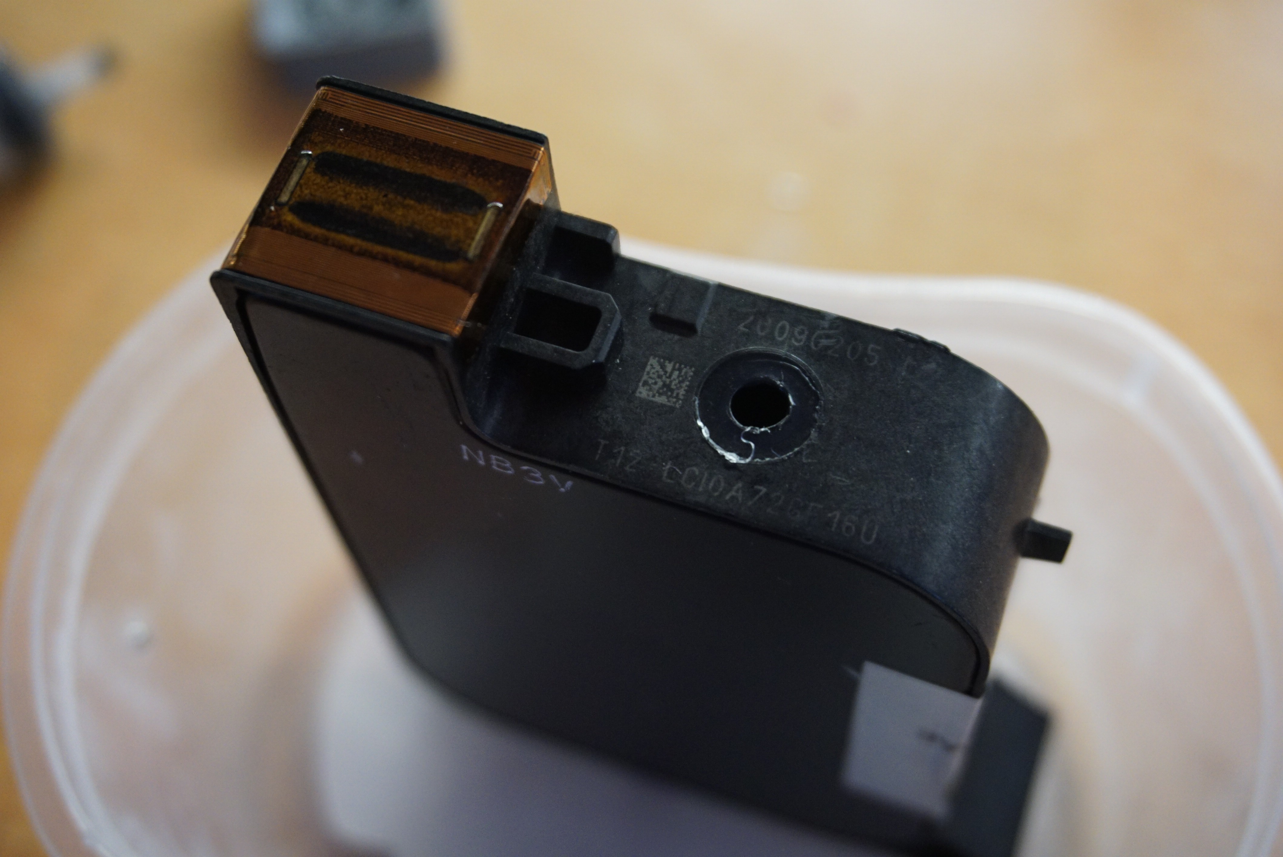
    The first important step is to print a new carriage. I thought the refill port was on the front, I though wrong. It is on the bottom. I want to plug the printhead with a screw and o-ring, so I need a hole there. I ran out of the faint blue, so I will be using the much nicer dark blue.

    To get a good idea of what the HP45 is, go here: http://wandel.ca/hp45_anatomy/. It has some great pictures of the HP45 itself and some explanations that will become important. Summary, a spring loaded tank that holds the ink under a vacuum.

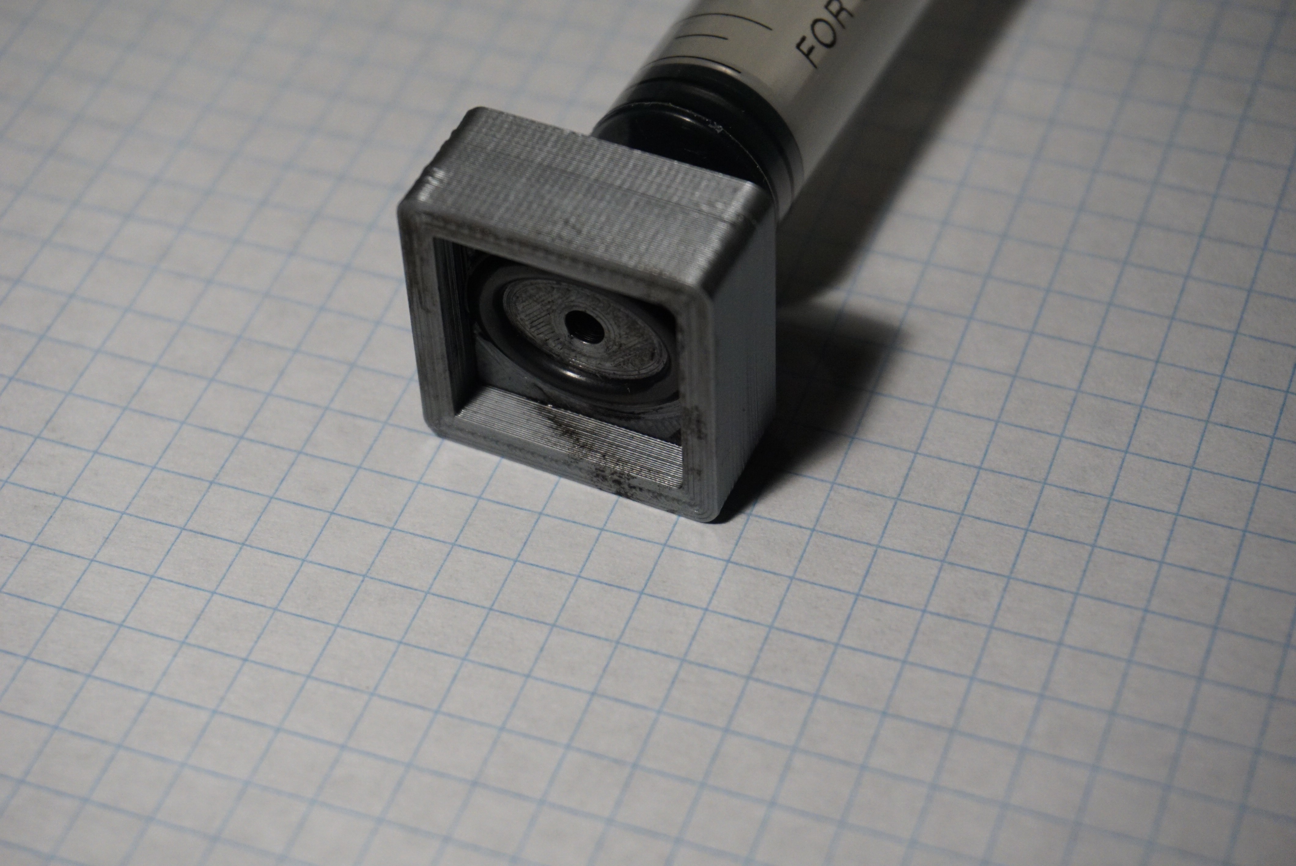
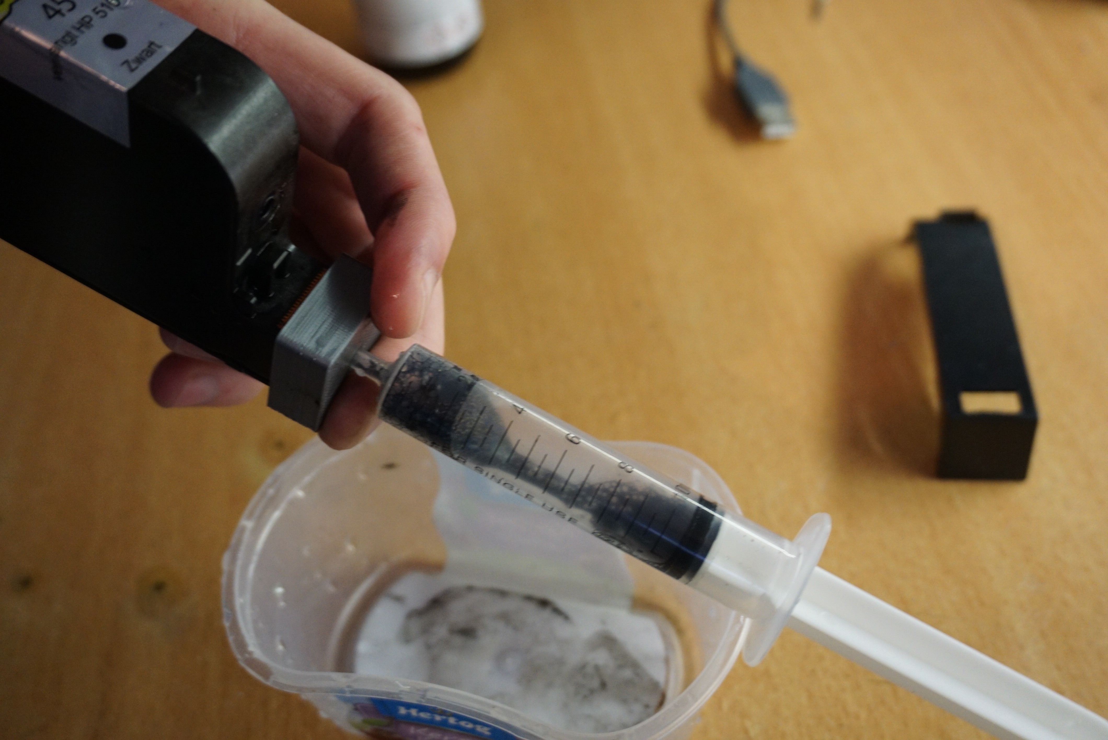
    I needed a few things to refill the printhead. The first is the binder. I also added some ink so I can see what I am printing. I chose blue because I like it. I also needed a syringe with needle, a lot of paper towels and running water. Refilling printheads is messy. You cannot believe how much ink can be diluted and still be completely black. Last I needed a suction head so I can draw the ink through the nozzles. This is a tool I 3D printed and added a o-ring to. It works shockingly well considering I spent 5 minuted designing it.
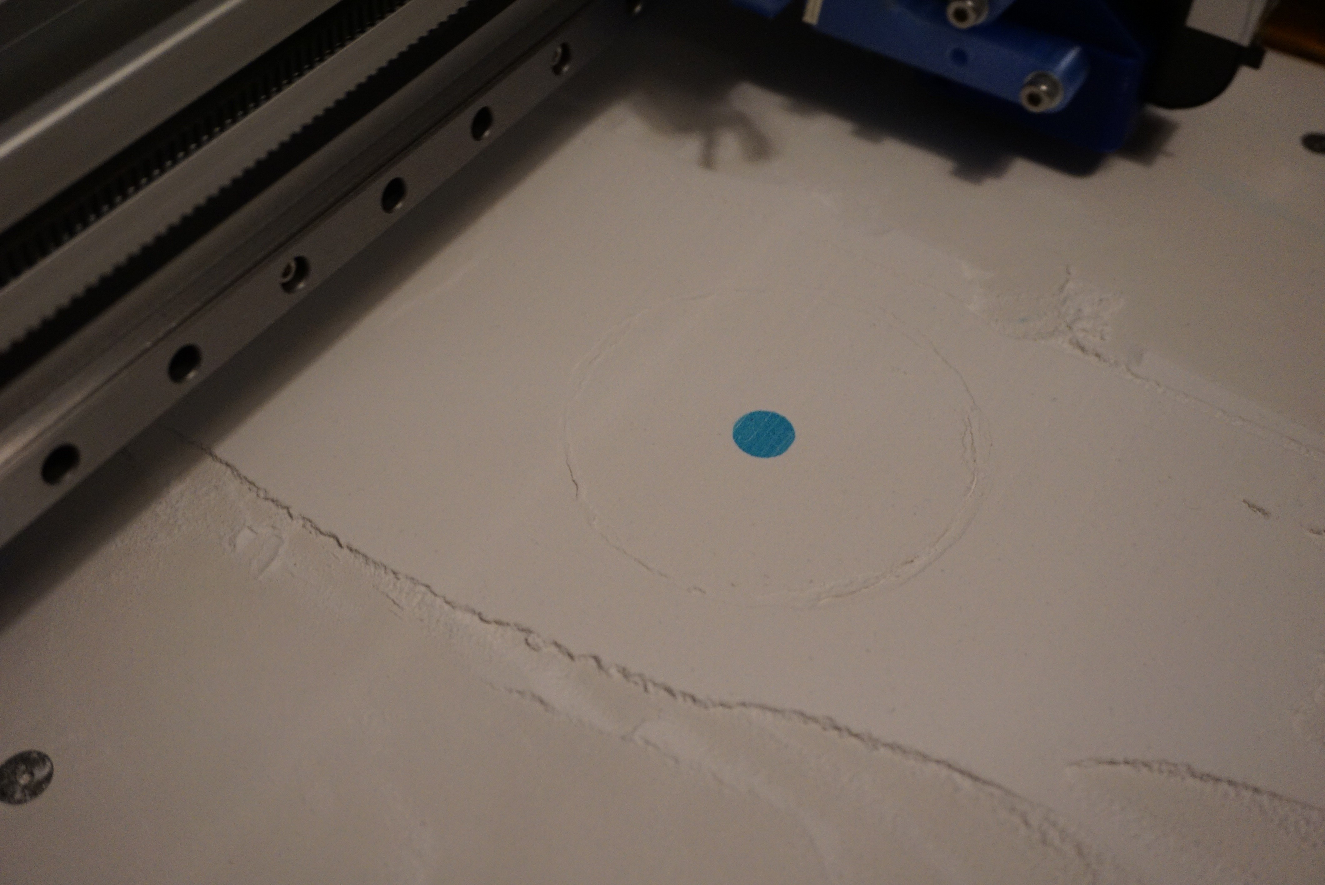
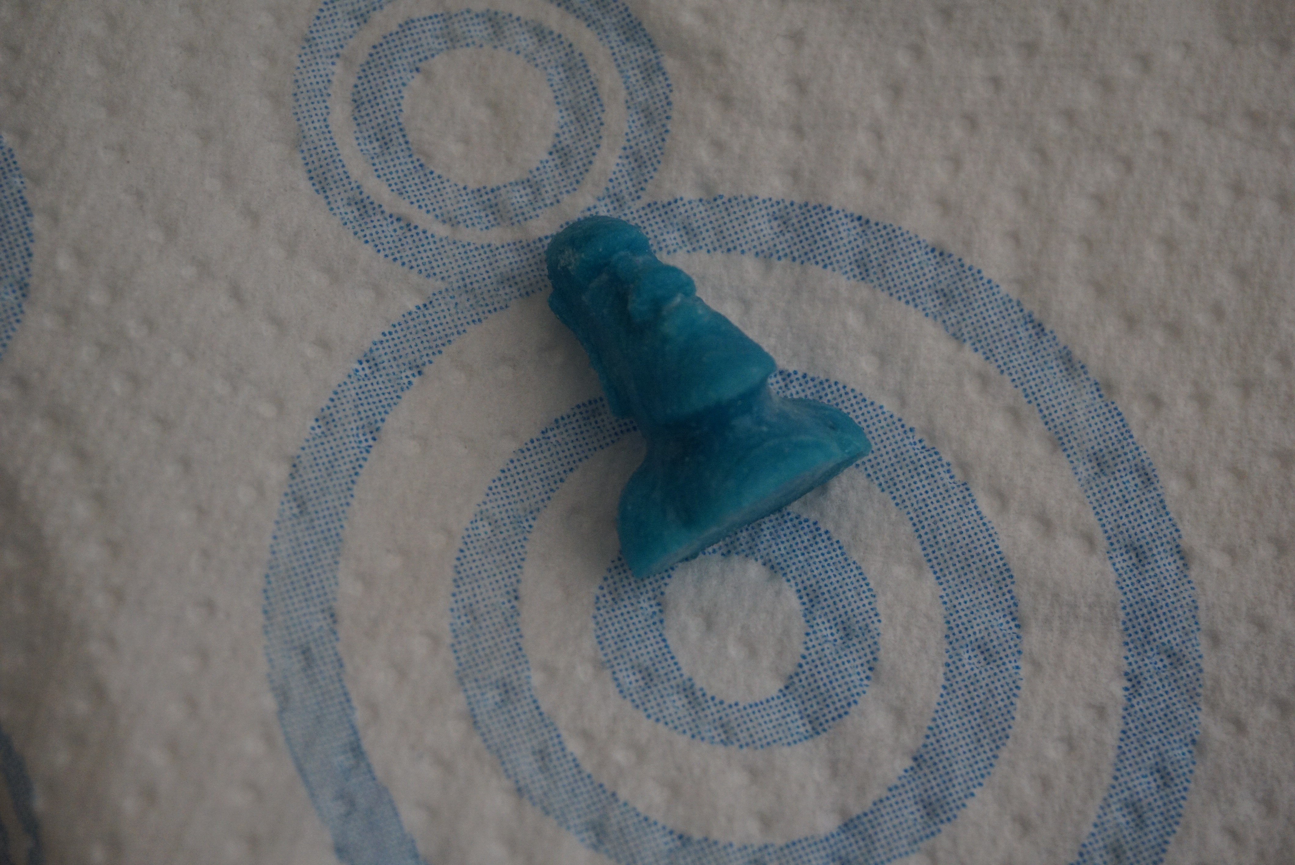
    Interesting note, the blue color of the prints now comes from the binder, not the powder. This is how you can add full color. CMYK and binder and you have a full color printer. I will investigate this after this first part of the project is done, but it is not part of the scope of this project itself.

    The rough list of steps needed to clean and refill a HP45 printhead:

    1. Take the sticker of the bottom;
    2. Push the ball sealing the printhead into the printhead;
    3. Squeeze (milk) the ink out of the printhead (it does not simply drain);
    4. Suction last ink through the nozzles using the tool;
    5. Fill with water/alcohol mix (or plain water for some of the repeats);
    6. Combination of milking the printhead and sucking ink through the nozzles;
    7. Repeat step 5 and 6 till water comes out clean;
    8. Refill printhead with binder (and optional ink, I did 1/20 cyan ink);
    9. Clamp the printhead with a strong clamp. The head should not have any air in it;
    10. Cap the hole. I used an M4 screw with a 3.5mm ID o-ring;
    11. Release the clamp;
    12. Suck the binder through the nozzles using the suction tool;
    13. The printhead now ready for use;


    I will post a proper guide later, mainly because I cannot save drafts in guides and like to write over a few days. I have plenty more pictures and detailed steps available, but I also have 100 other tasks that need doing right now.

    A thing I discovered very quickly is that the vacuum on the printhead is really necessary. Previously I just filled the head without the clamp. After a single burst of ink there was ink leaking from the printhead. I then opened the head, clamped the body with a clamp, and closed it again. This time it printed perfectly.
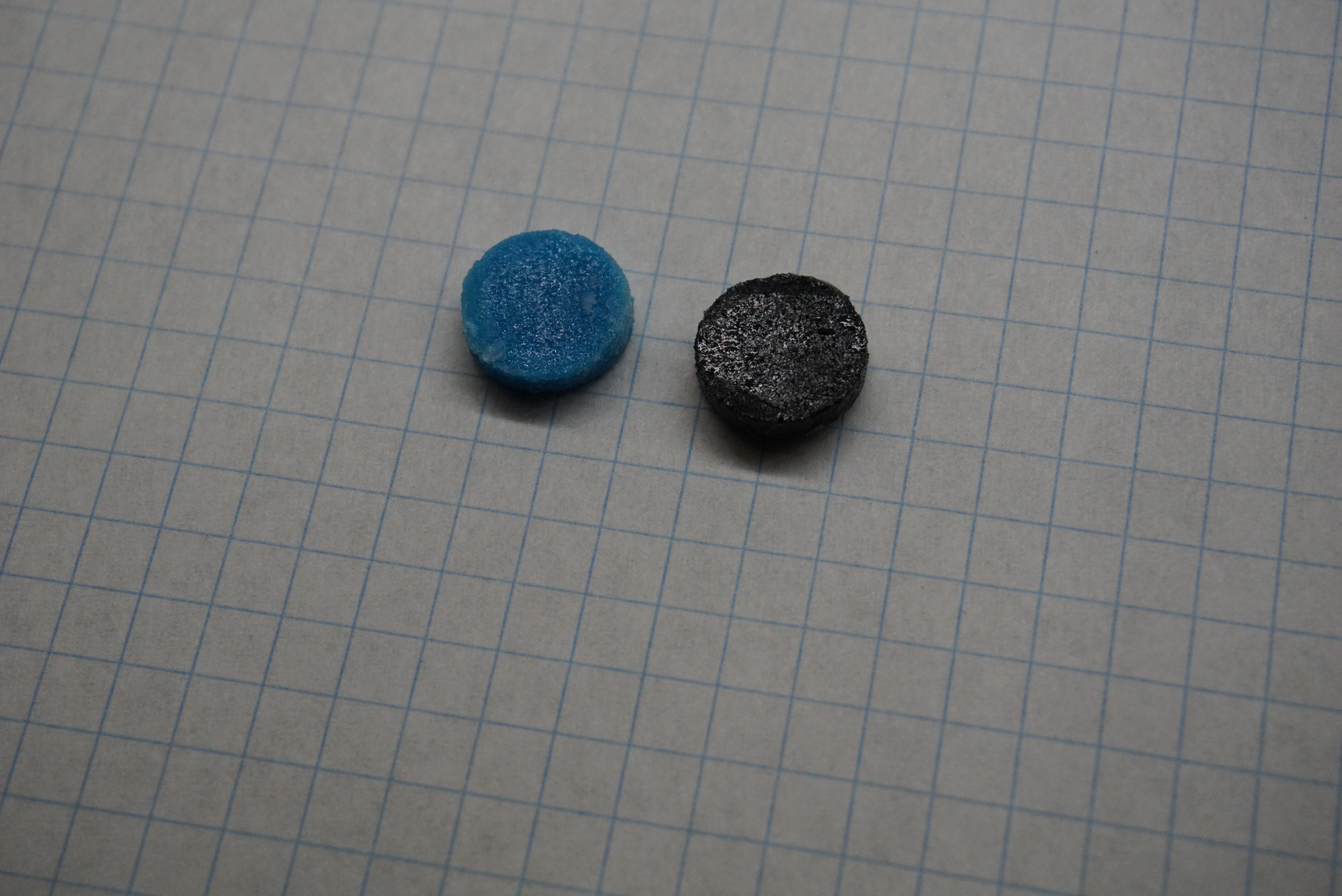
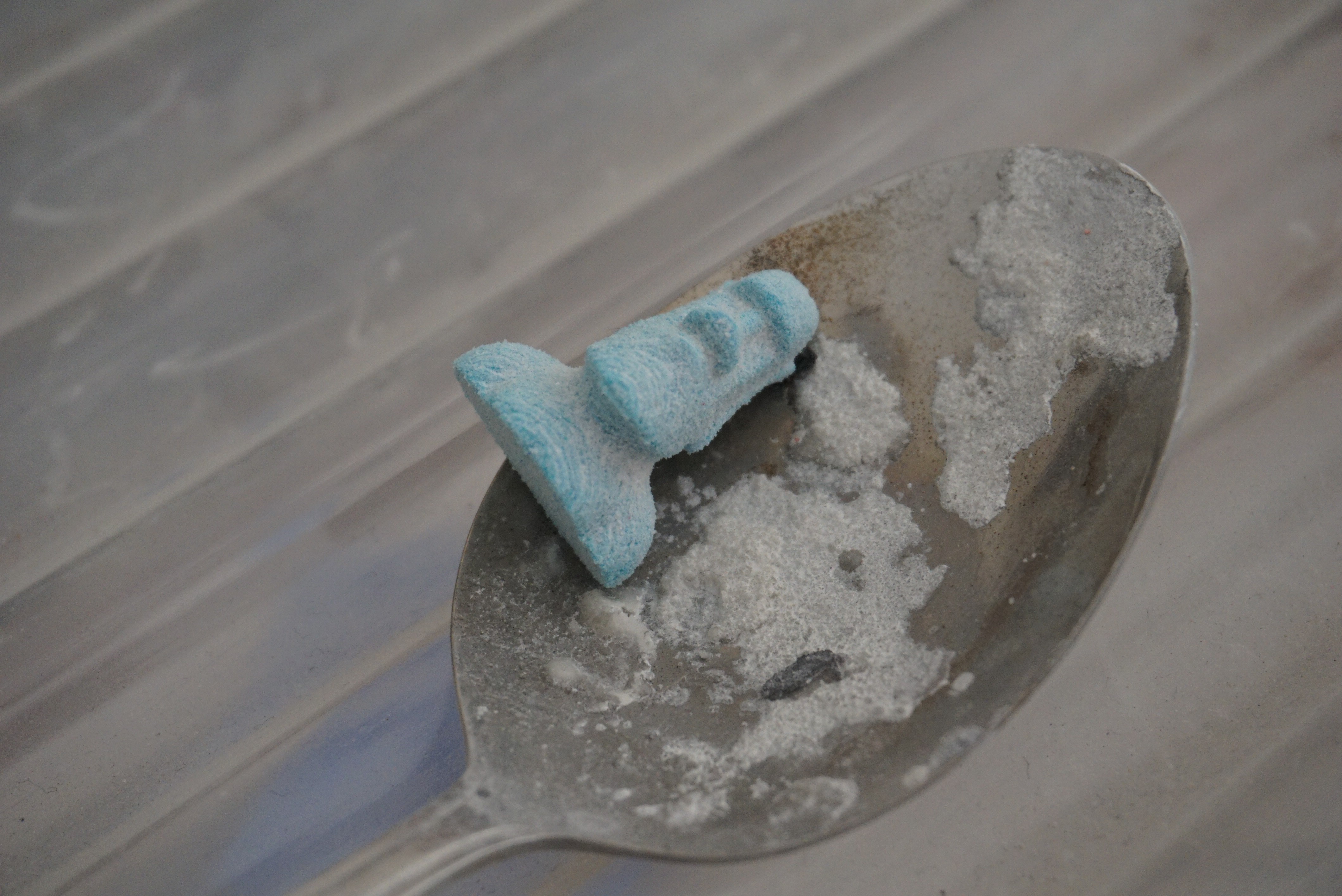
    Another thing you will find out (I did at least) is that refilling a printhead is messy. Once the ink touches your hand, it stays there. My hands are various nice shades of black and blue. Next time I will be wearing gloves.

    I have heard (but not confirmed) that you can replace the milking and sucking with a centrifuge. I have no centrifuge here, so for me it will stay a mystery, but it is a nice thought.

    I will be printing with this binder for the coming few days, trying to dial in the ink percentage and trying to print some nice objects.

    Left binder, right pure ink
    https://www.thingiverse.com/thing:149271
    Printed in glorious blue

    More coming soon, this project is now really moving.

View all 25 project logs

  • 1
    Before you start assembling

    You want to build an Oasis. Neat. Be aware that it is a prototype and not a finished, optimized product. Toolchain, Software and firmware still needs to be optimized. Why is there documentation if it is not finished. Because it works.

    All the most up to date files for Oasis are here, in the file section of the Hackaday.io page. To make an Oasis you will need 3 files the most. The first is an excel file called 'Oasis total BOM *date*'. This contains the full Bill of Materials for Oasis, mechanical  and electrical. The second is 'OA-Y00-A01-00 3D-PDF *date*' This is a 3D PDF of the mechanical build of Oasis. This should help aid in the building of Oasis. The last is a zip file 'Oasis make package *date*' This contains all files and drawings to make an Oasis.

    After extracting you will see 4 folders. 'Electronics', 'Firmware', 'mechanical', and 'software'. Each folder contains all necessary files to make an Oasis for that category.

    In 'Mechanical' There is a certain file structure in the names. All custom parts and assemblies have the name: 'OA-Ynn-Ann-nn' or 'OA-Ynn-Pnn-nn', where 'n' is a number. 'OA' is the project (Oasis), 'Ynn' is the group, or subassembly. 'Pnn' is a part, 'Ann' is an assembly, and the last 'nn' is the revision. The project starts at 'OA-Y00-A01-00' (as of writing. If you see a higher revision, don't worry and pick that). This contains the full drawing of the assembly, and refers to other subassemblies and parts.

    In each subfolder you will find at least one PDF drawing of that subassembly, PDF drawings of parts you might need to make, and STL files of parts you need to print. All drawings and step files are accompanied with STEP files you can open in many CAD packages for reference or to change them.

    These drawings, accompanied with the 3D PDF, should help you assemble the mechanicals of Oasis.

    Now the bad news. I do not have a full set of photos in the order of assembly. I built what is in the files over 3 months, improving parts as I built. In my drawings, I tried to give a good suggestion for order, but the photo's will not follow that. If you want to assemble it in your own order, feel free. All the the provided photo's are for reference and not in chronological order at all. Nonetheless I hope they will be useful.

  • 2
    Assembling electronics

    The electronics can be installed afterwards, but in order to keep this guide as chronological as possible, it is first time to assemble the electronics. In the BOM, under 'Electrical' you will find a list of components, including what name they have on the PCB, and the footprint.  I will be hand soldering SMD in this example, so it might be a bit messy in places.

    HP45 driver board

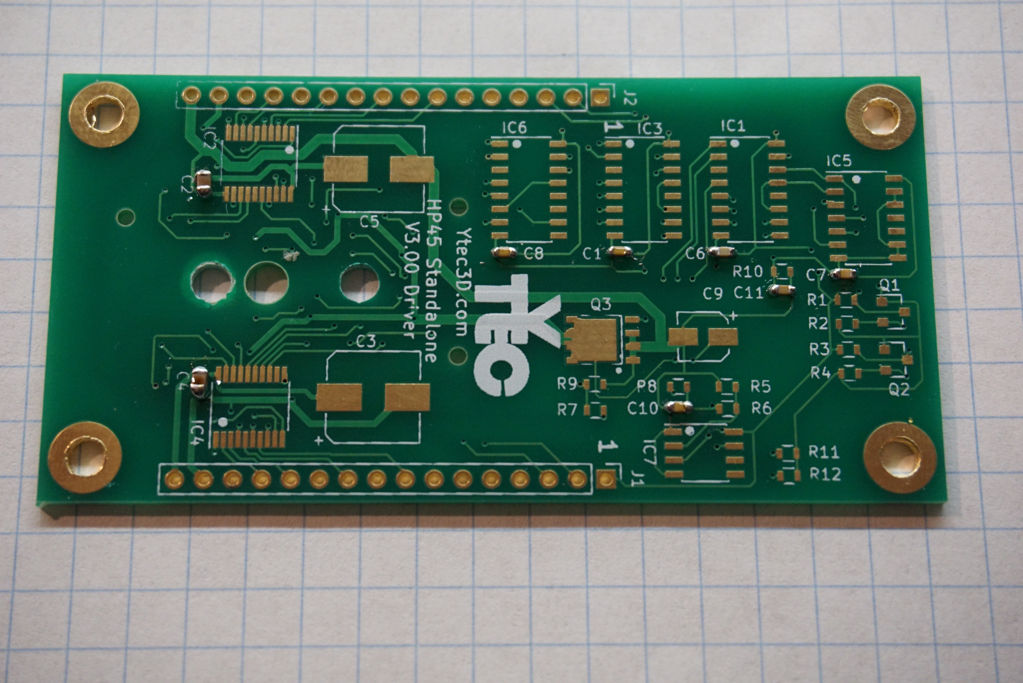
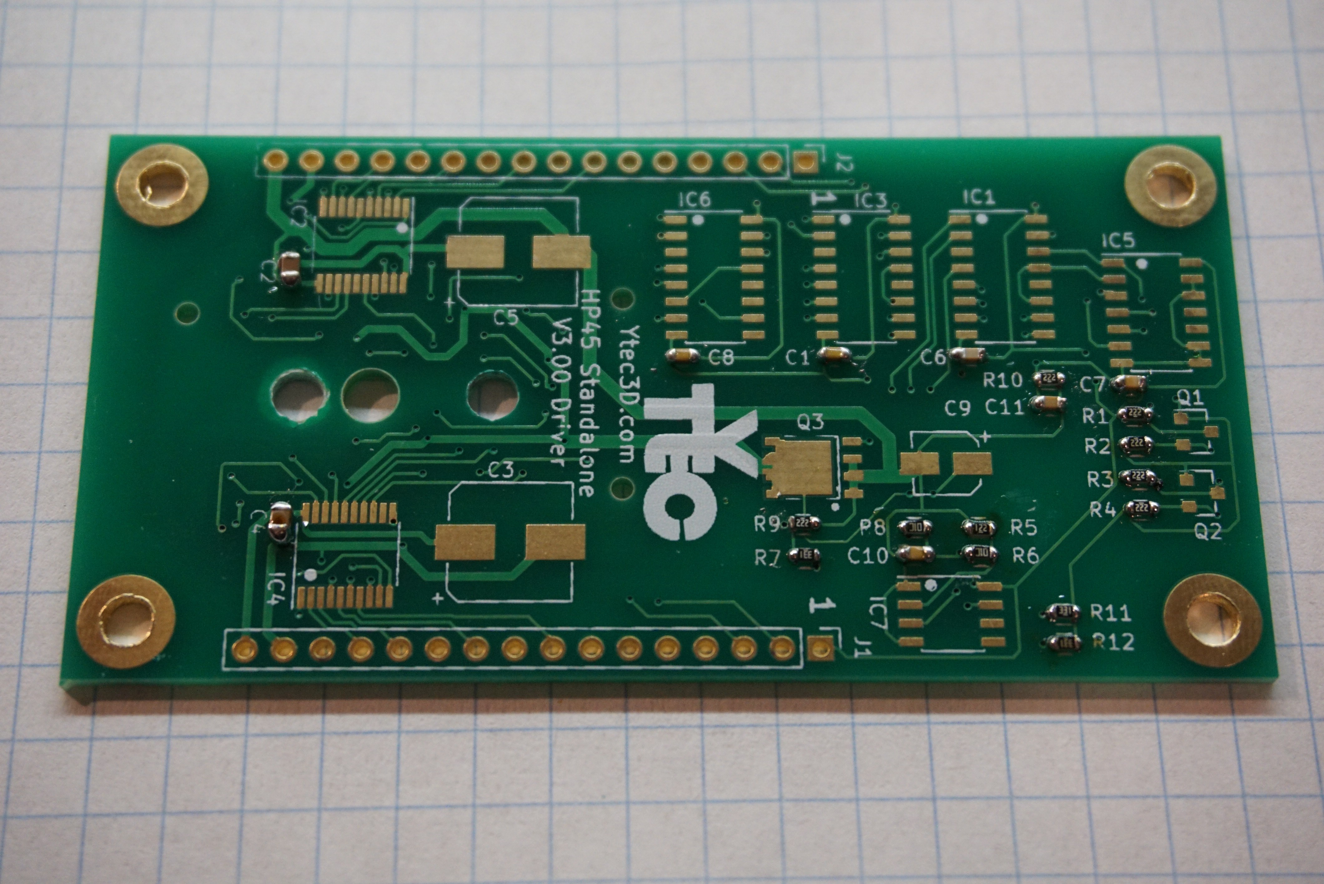
    The first board and the most complex board is the driver. This driver board controls all addresses, primitives and has the ability to test the nozzles.

    Install the capacitors. The footprint of the capacitors is 0603 and they should be at least 16V. C1, C6, C7, C8, C10, C11 are 0.1uF,  C2, C4 are 1uF. Polarity does not matter on these capacitors.


    Install the resistors. The footprint of all resistors is 0603, they should be 1% and need to be around 0.1W. R7, R11, R12 are 330Ω, R5 is 1.2kΩ, R1, R2, R3, R4, R9, R10 are 2.2kΩ and R6, R8 are 10kΩ.

    Install the mosfets. There are several types. Q1 and Q2 are the small ones. They are PMV20CNER and have a SOT-23 footprint. They only serve to shift level, so any low threshold voltage N channel mosfet should work. Q3 is the big one. It is a SIRA12DP-T1-GE3 in an SO-8 power pack. It needs low on resistance and a gate voltage lower than 3V. The dot marks the orientation for Q3.
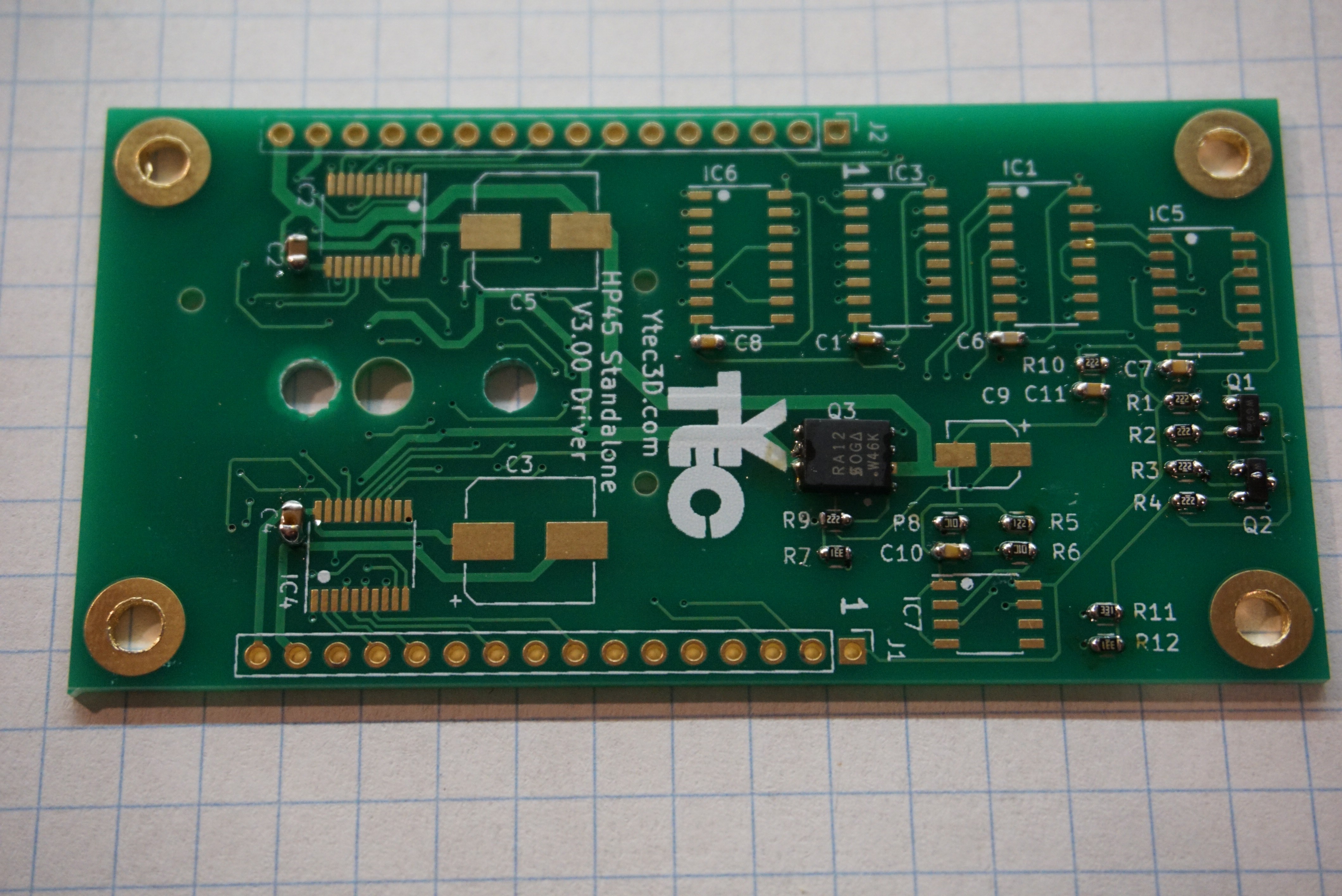

    The IC's are plentiful on the driver board. IC1, IC3, IC6 are HEF4017 with package SOIC-16 3.9mm. The exact 4017 is not important, only that it is at least 15V. IC5 is HCF4081, the package SOIC-14 3.9mm. Again, only voltage is important. IC2, IC4 are TLC59213. Rhese will be most difficult to solder. The package is TSSOP-20. Foot pitch is 0.65mm. The last component is C7, LM311. It is SOIC-8. On all components there are dots and marks to indicate orientation.

    Install the Electrolytic capacitors. C3, C5 are 100uF, 16V minimum, package 8mm, height lower than 10mm. C9 is 1uF, 16V minimum, package 4mm.

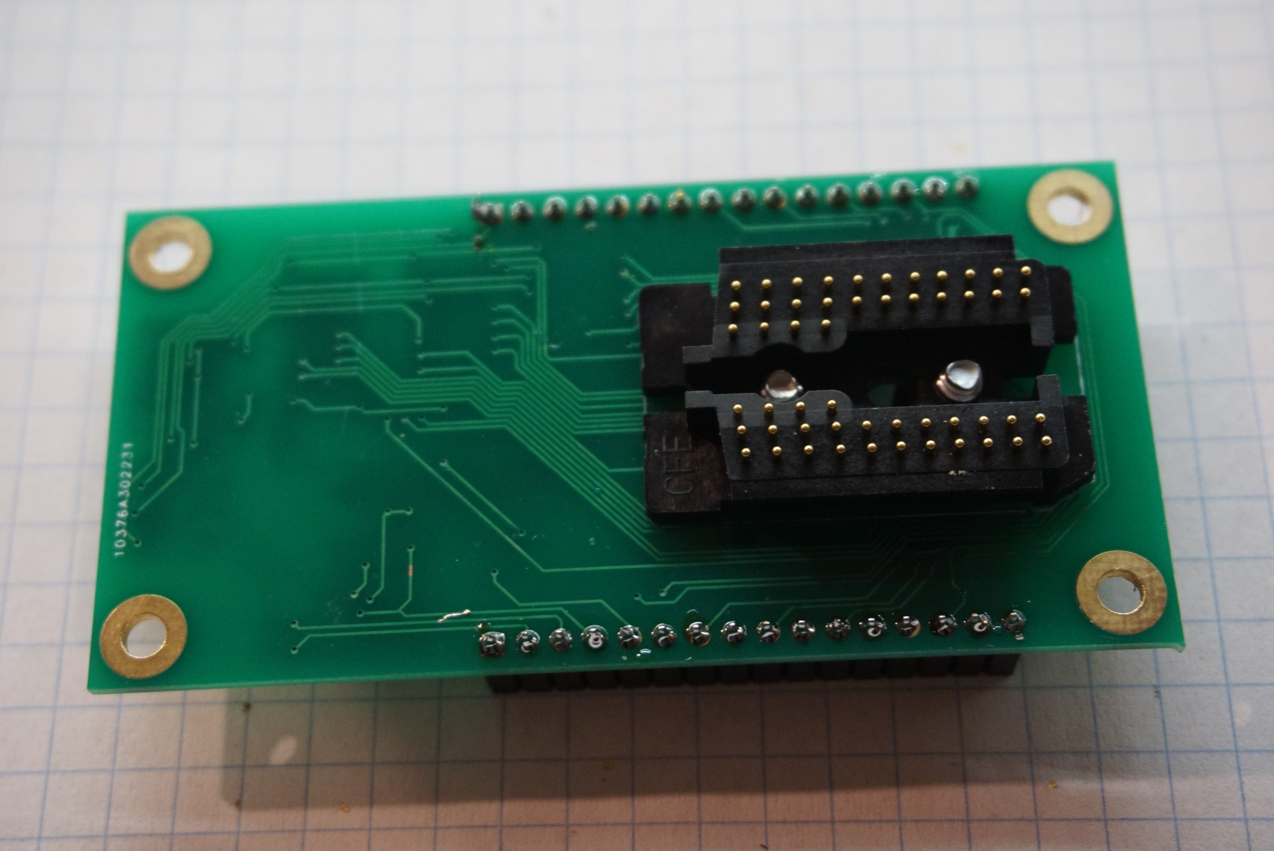
    Mount the HP45 connector using M3x6 or #6 screws (I am experimenting with #6, if they behave I will include them in what I sell. The holes are not actually big enough for #6, so I do have to ream the holes right now.
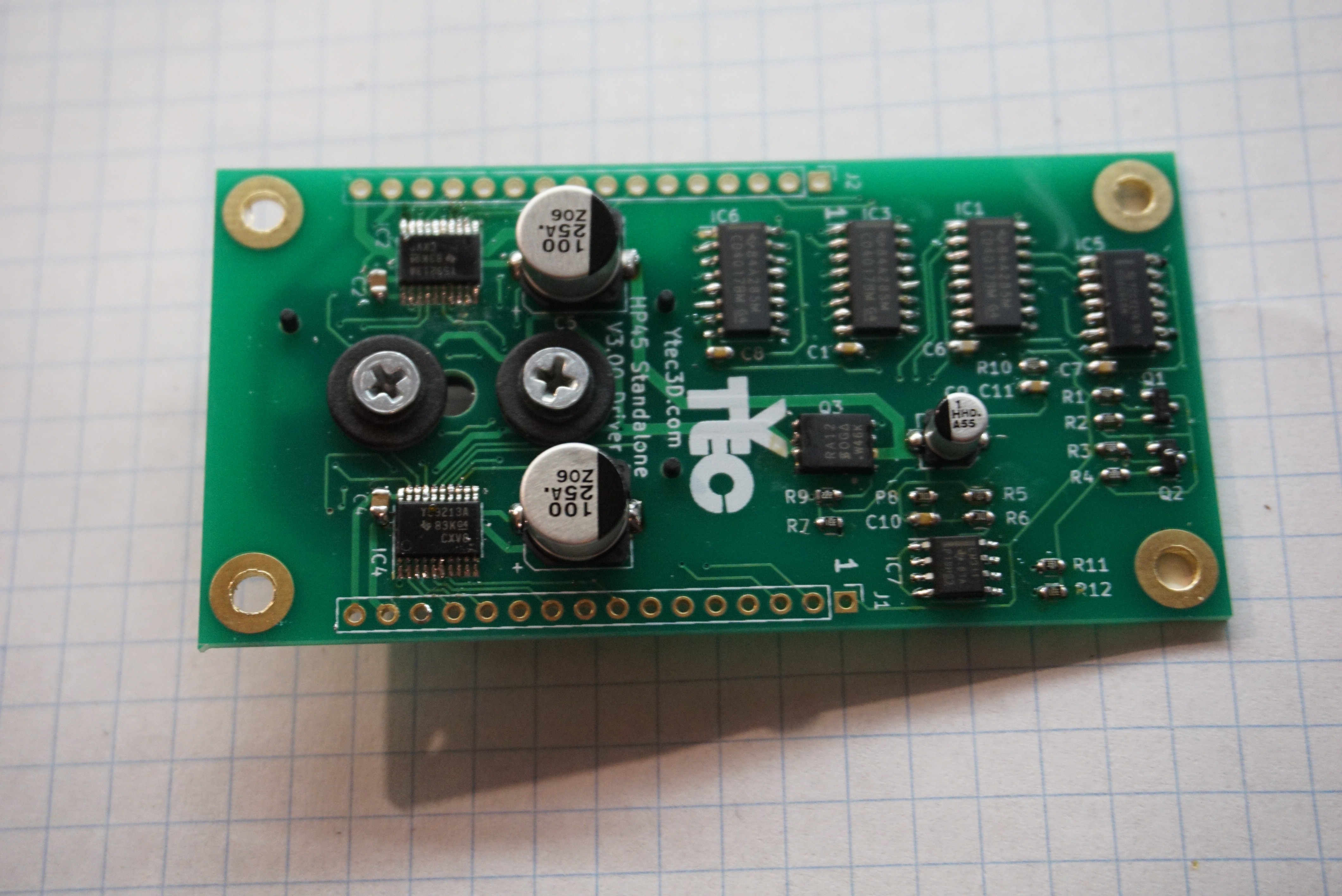
    2x 16 pin female headers, 2.54mm (J1, J2)
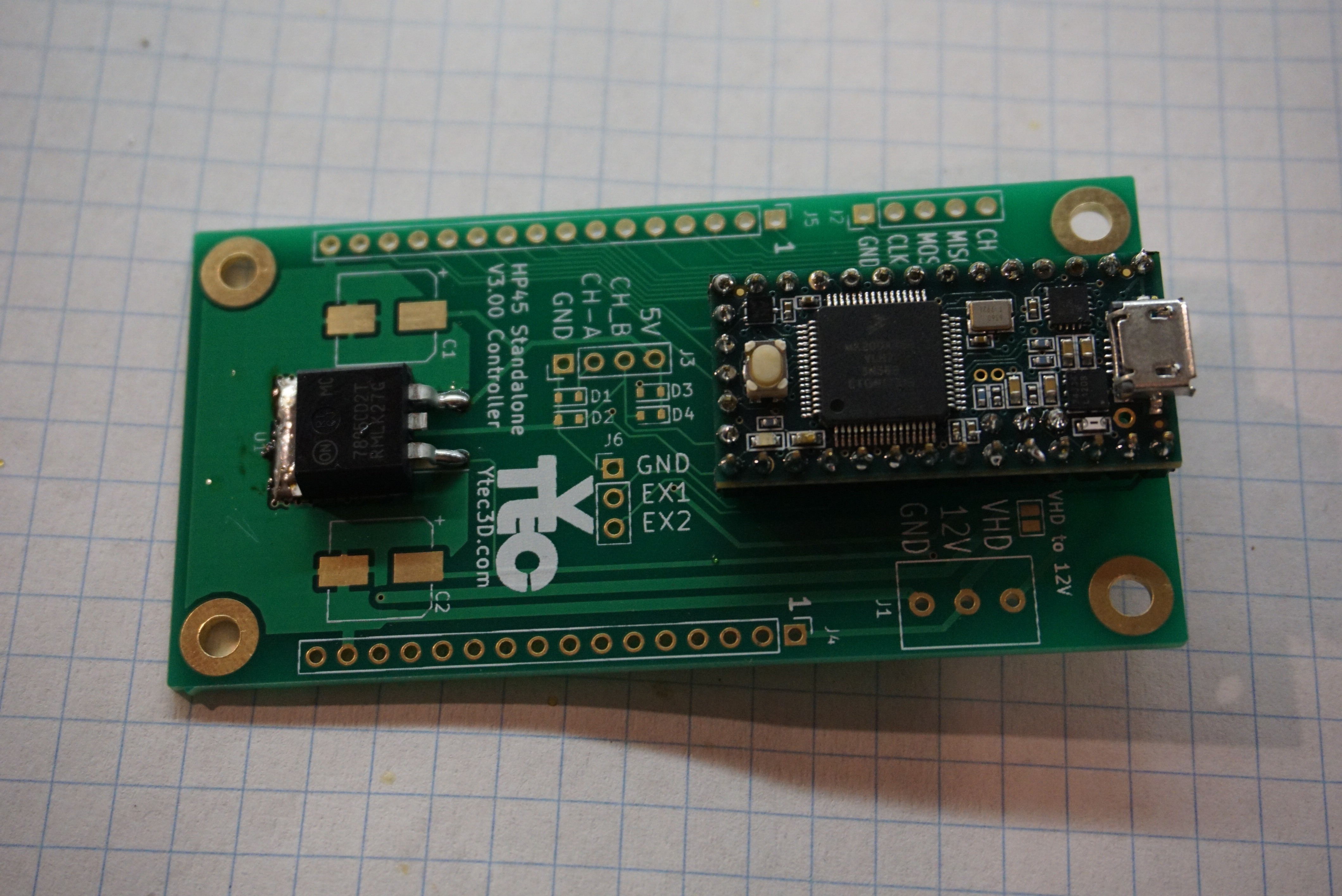
    HP45 controller board

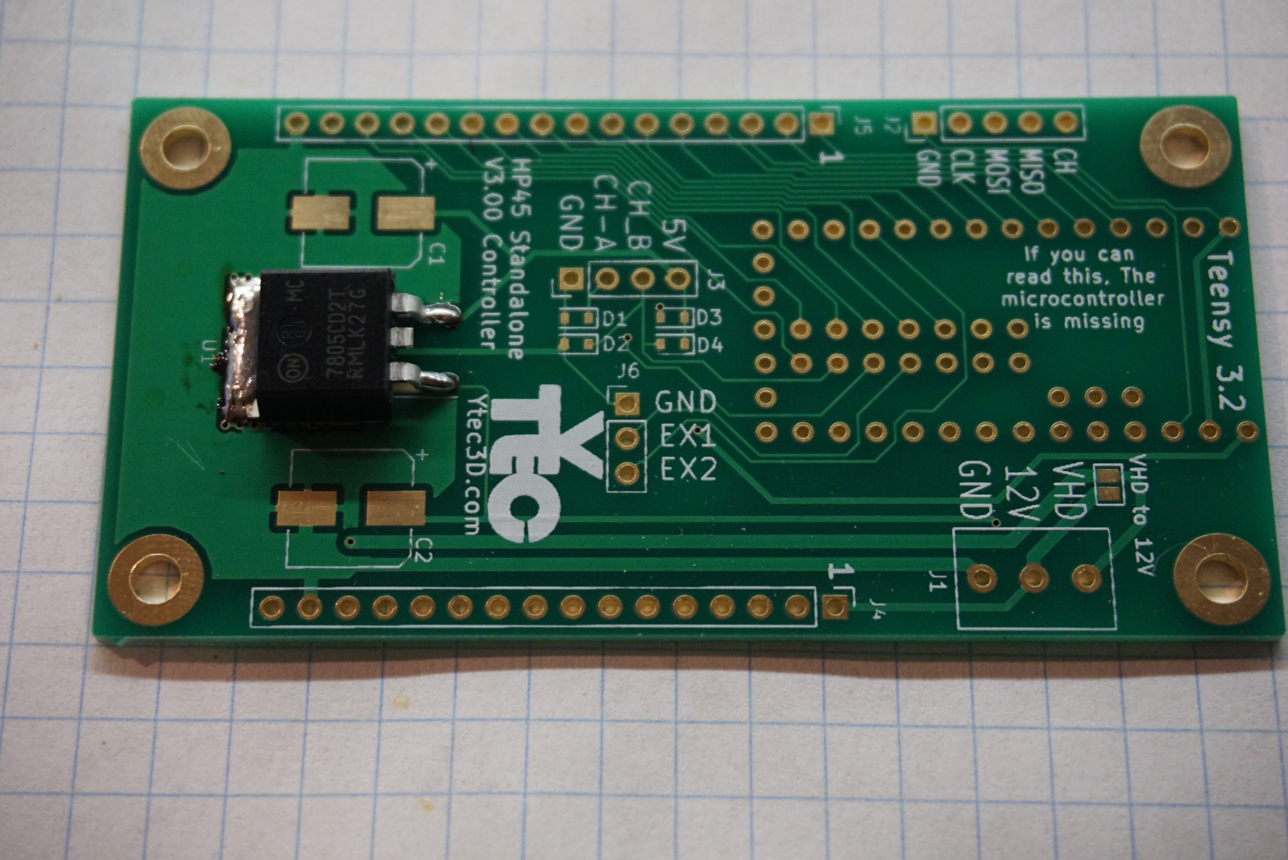
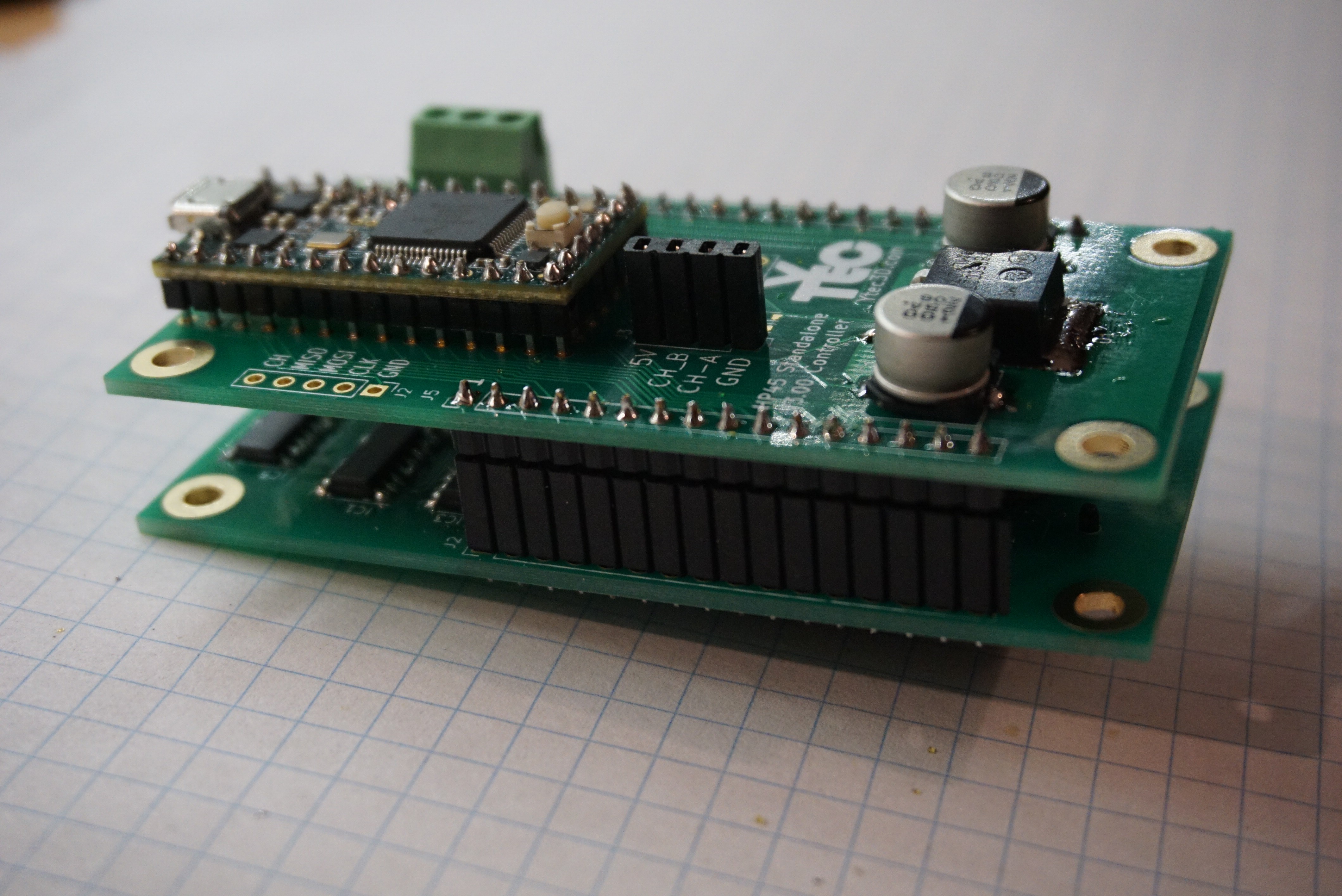
    Mount the U1 7805 voltage regulator, footprint TO263-2.


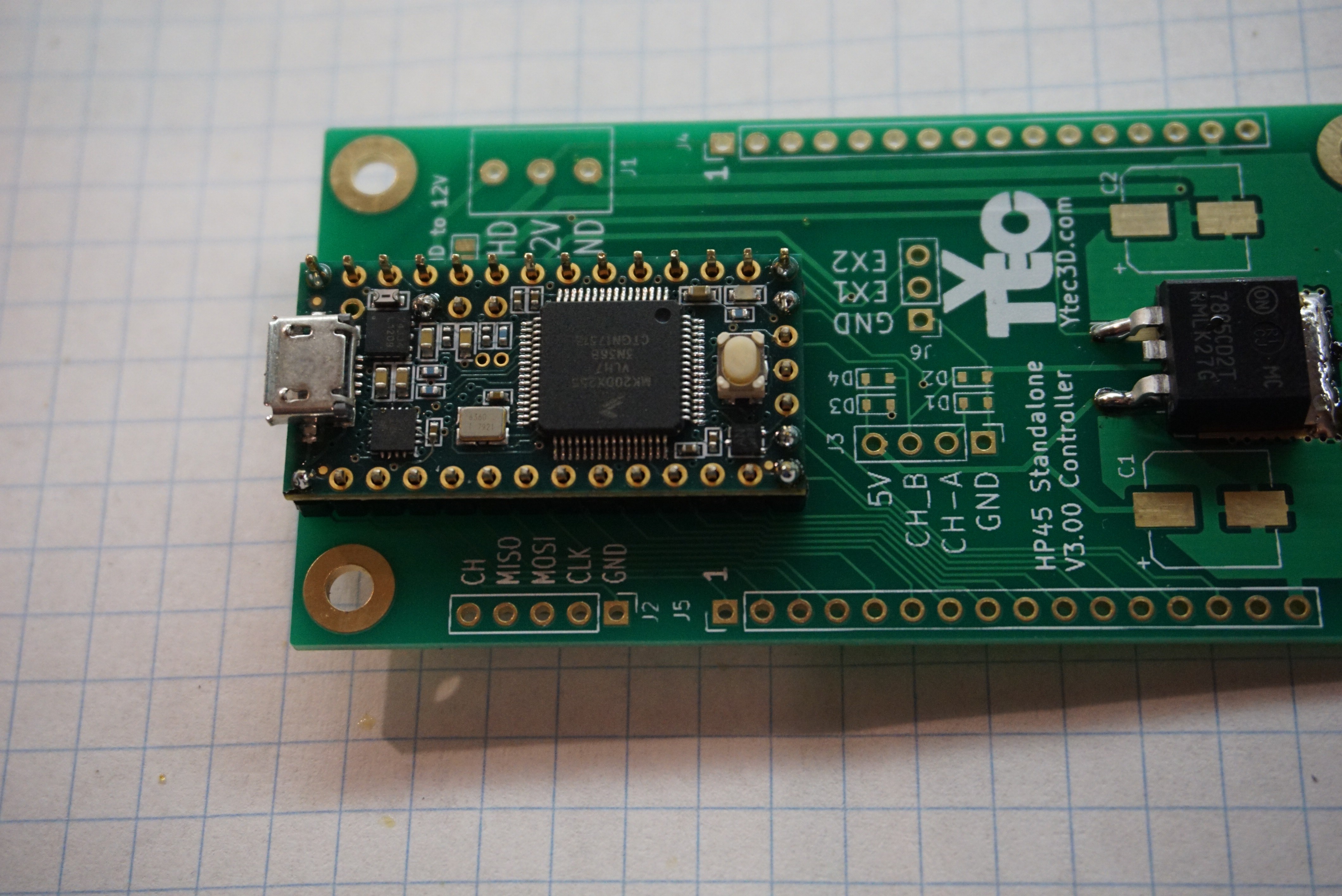
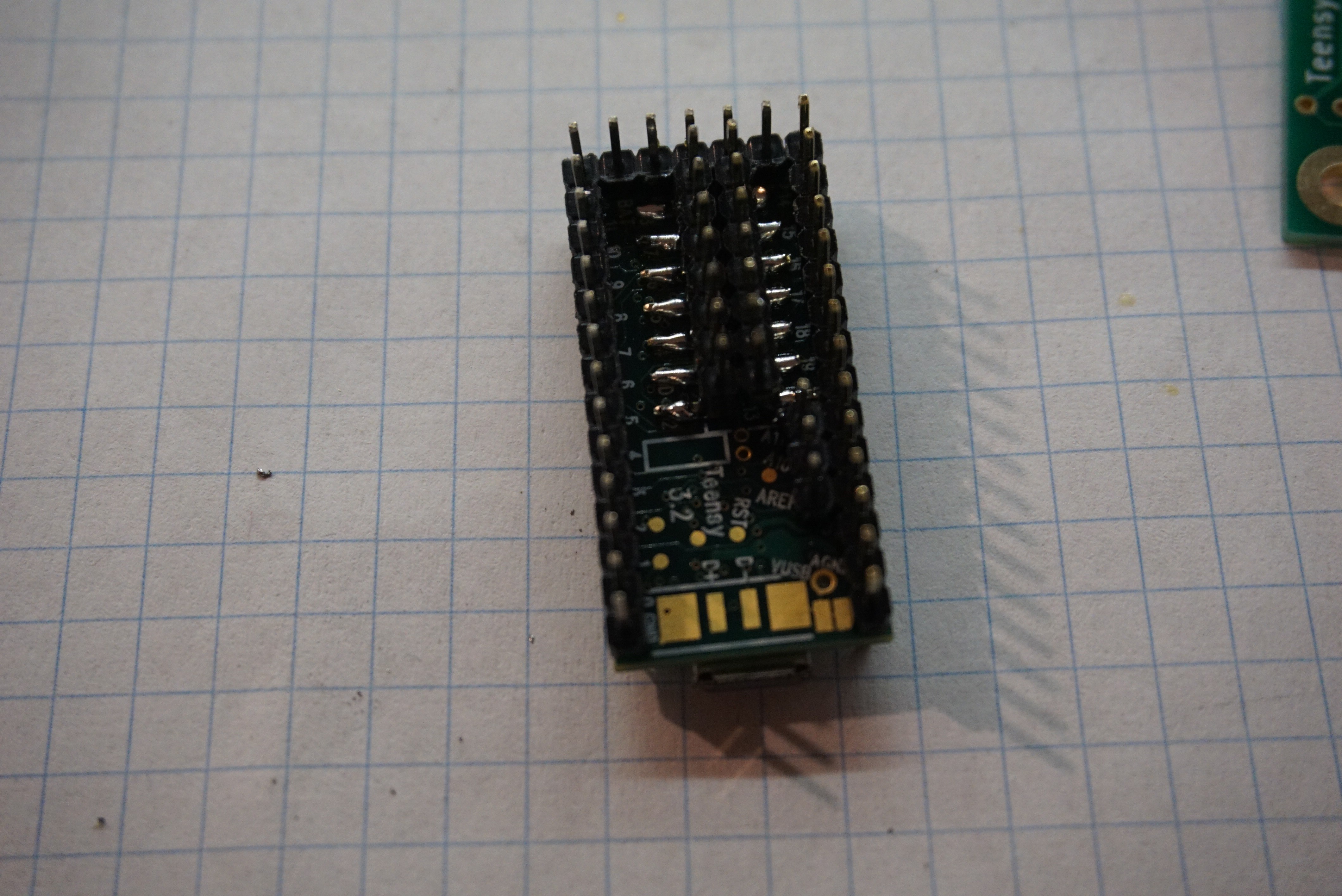
    Place the Teensy 3.2 on the controller to align the male headers. Solder a few of the pins on the Teensy (But NOT on the PCB) to secure the headers. You'll need 2x 1x14, 1x 1x5 and 1x 1x3.

    Solder SMD male header 2x7 (or 2x 1x7) under the Teensy 3.2. Make sure it is aligned with other headers. Make sure all SMD pads under teensy make good connection to the Teensy if you permanently solder it in place. Once it is in place, you cannot access it to repair a solder joint.

    Solder the Teensy 3.2 to controller board. Here you can optionally solder female headers to the board. Be aware though that this will increase the height of the whole assembly to a point where it will not properly fit in Oasis.
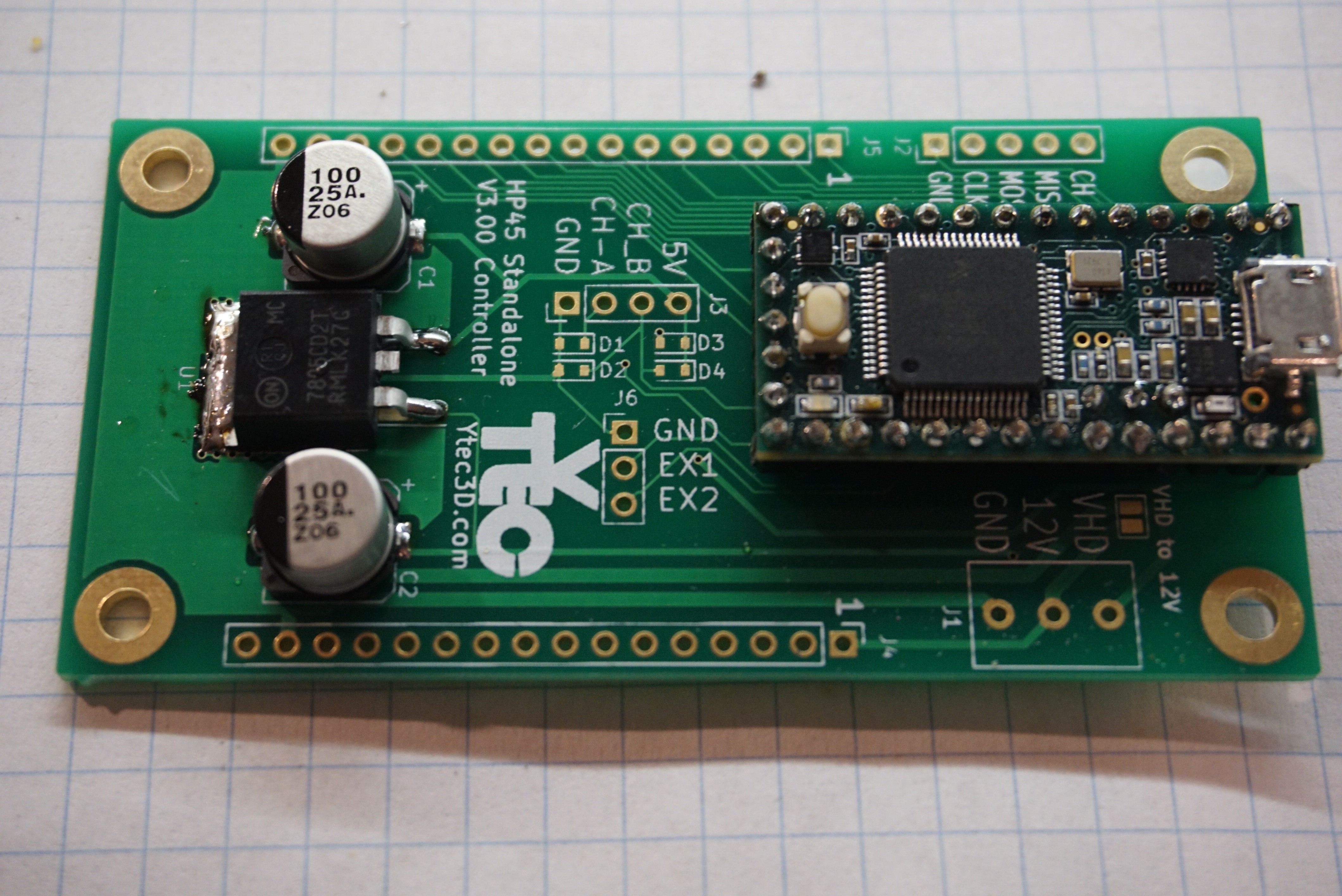
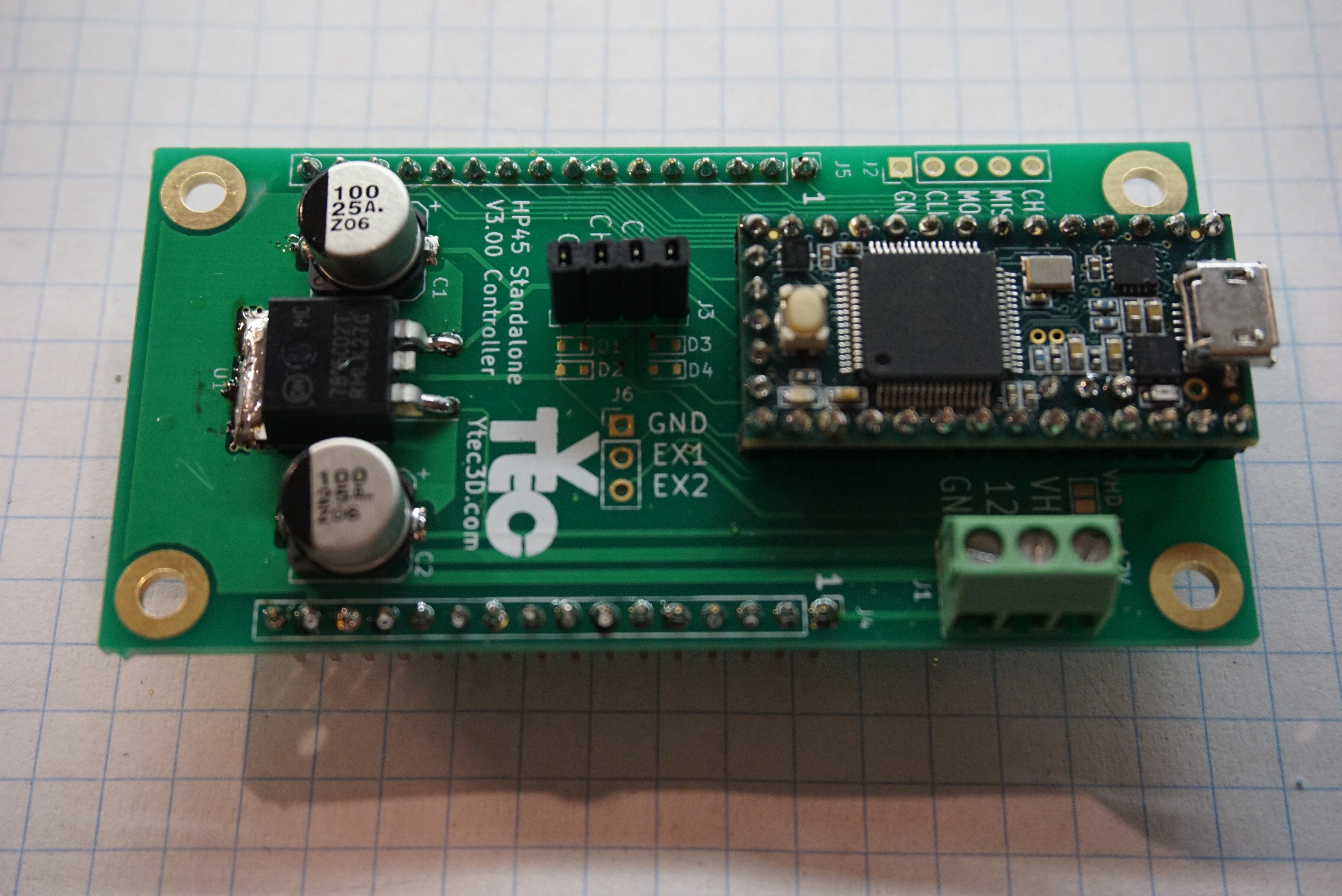
    Solder the electrolytic capacitors C1, C2. 100uF, 16V min, package 8mm.


    Solder the male headers 2x 1x16, 2.54mm pitch (J4, J5), 1x4 female header, pitch 2.54mm (J3). 1x3 3,5mm screw terminal (J1).

    Put boards together and enjoy.
  • 3
    Assembling the frame

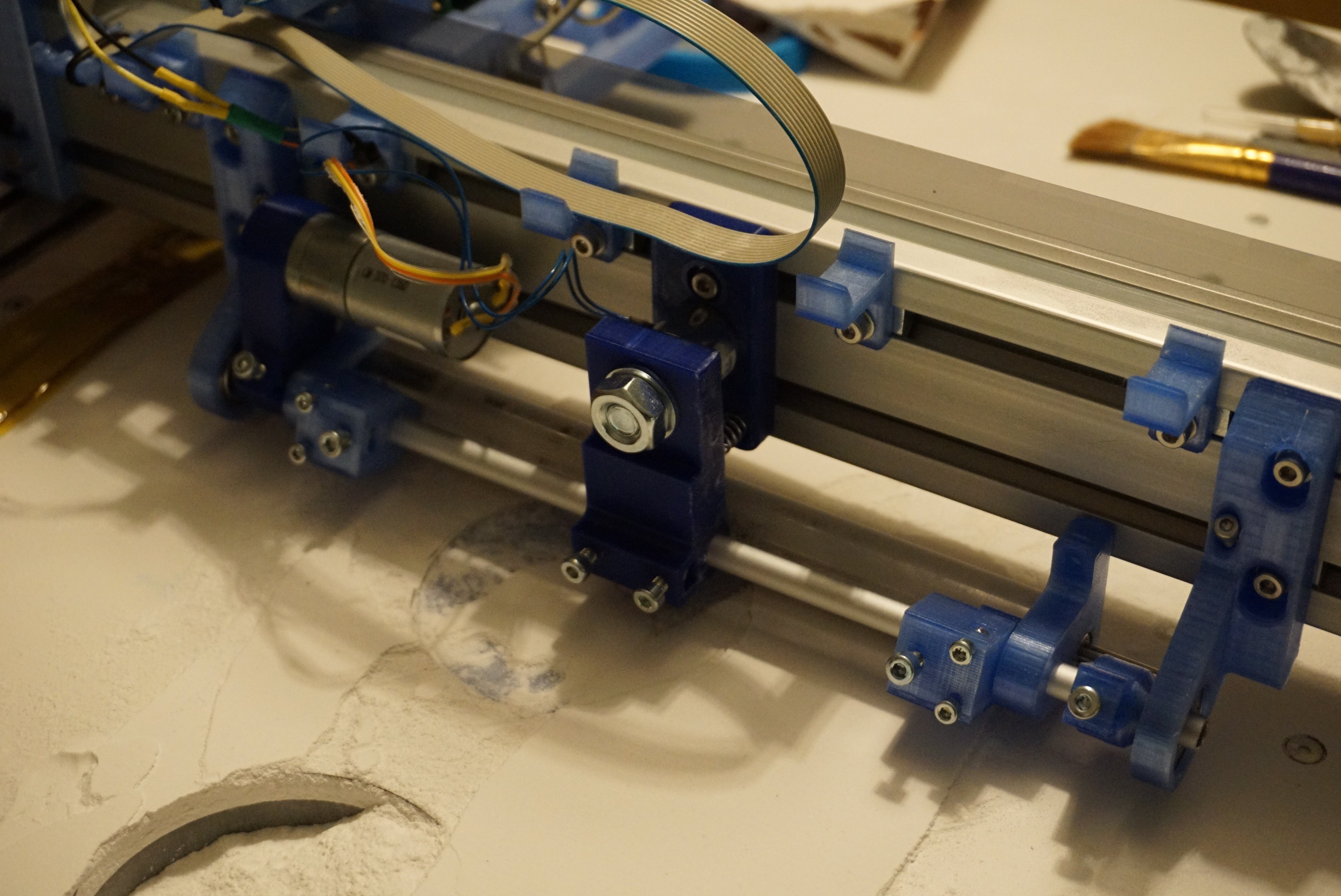
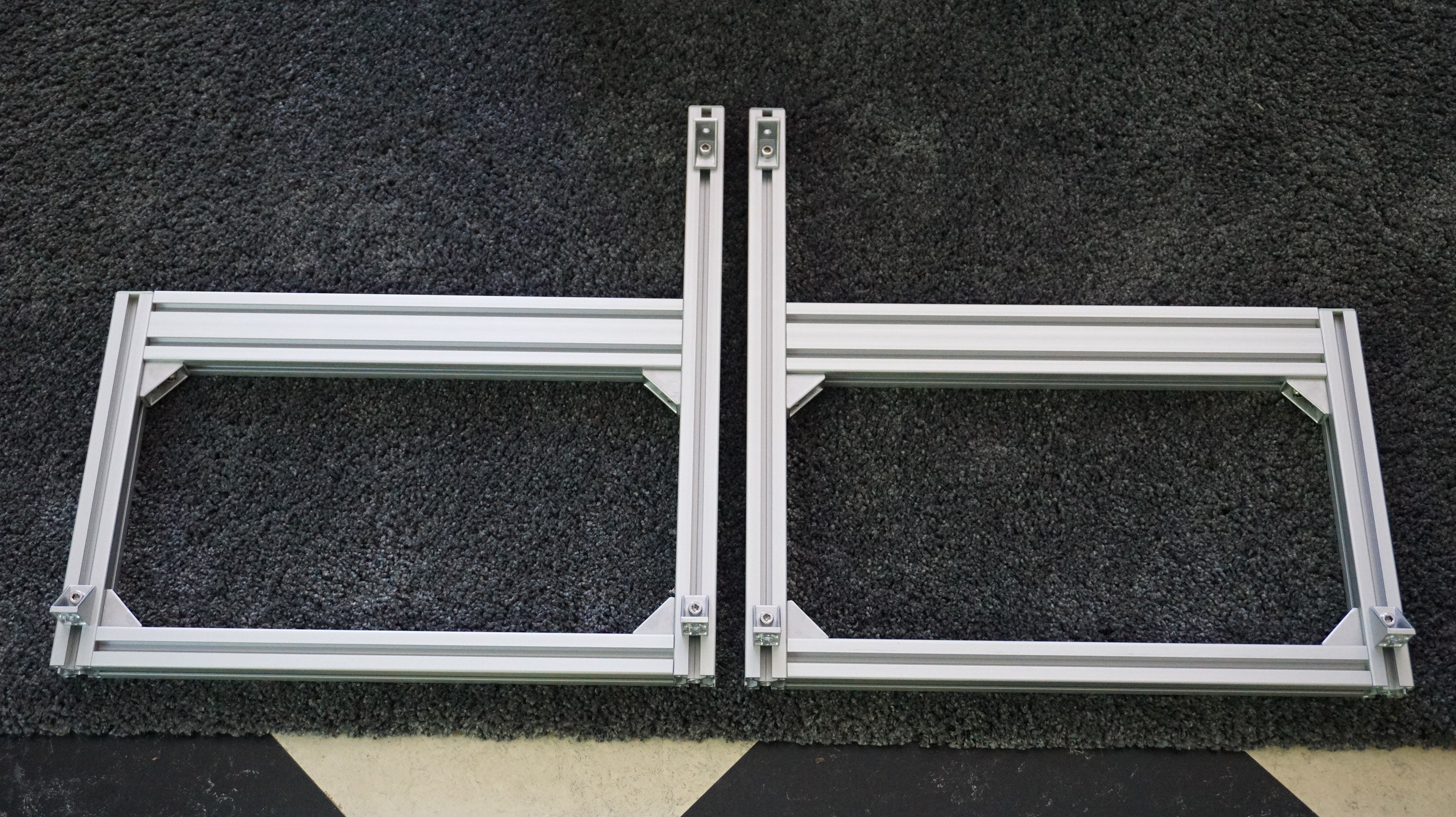
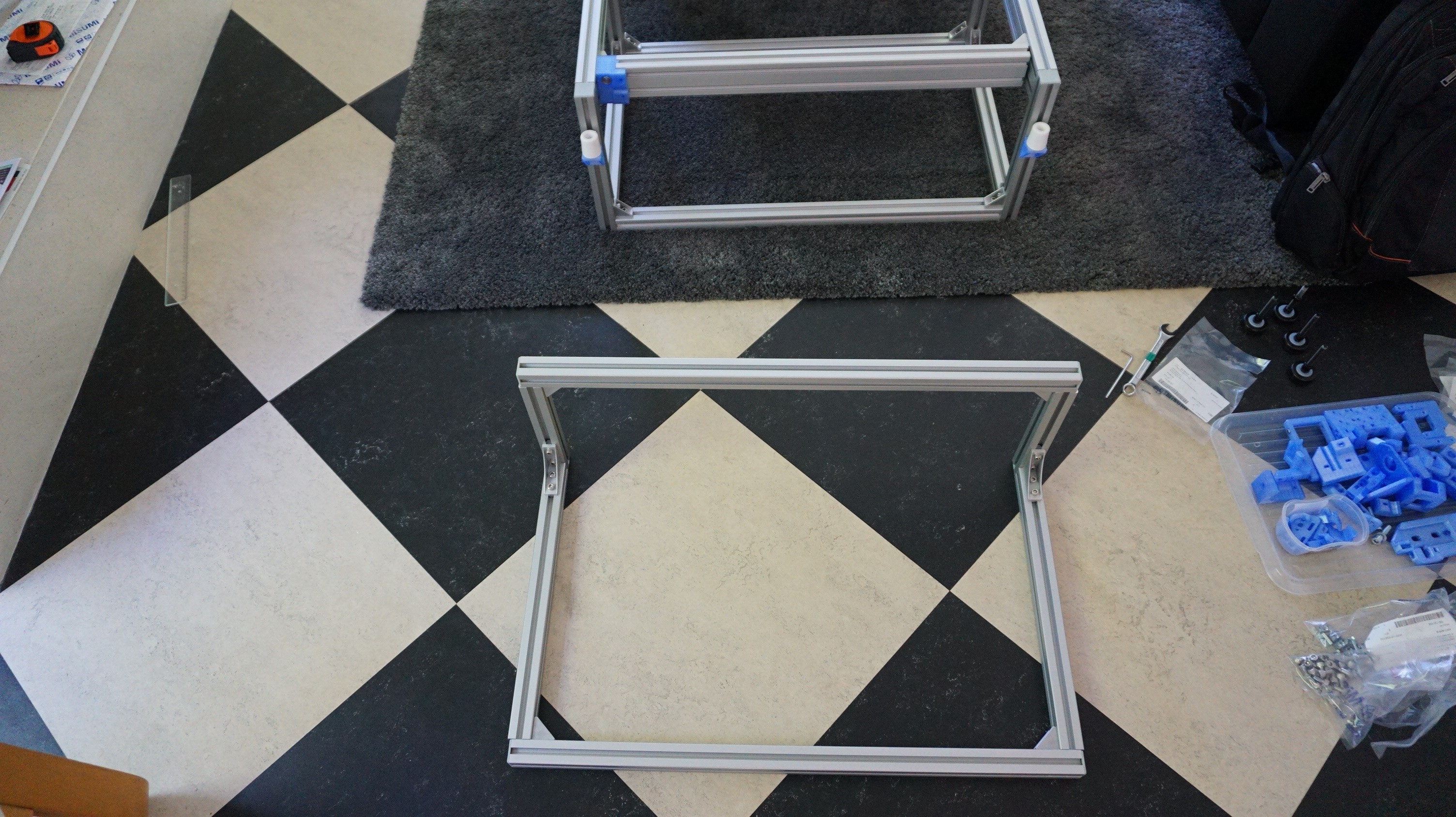
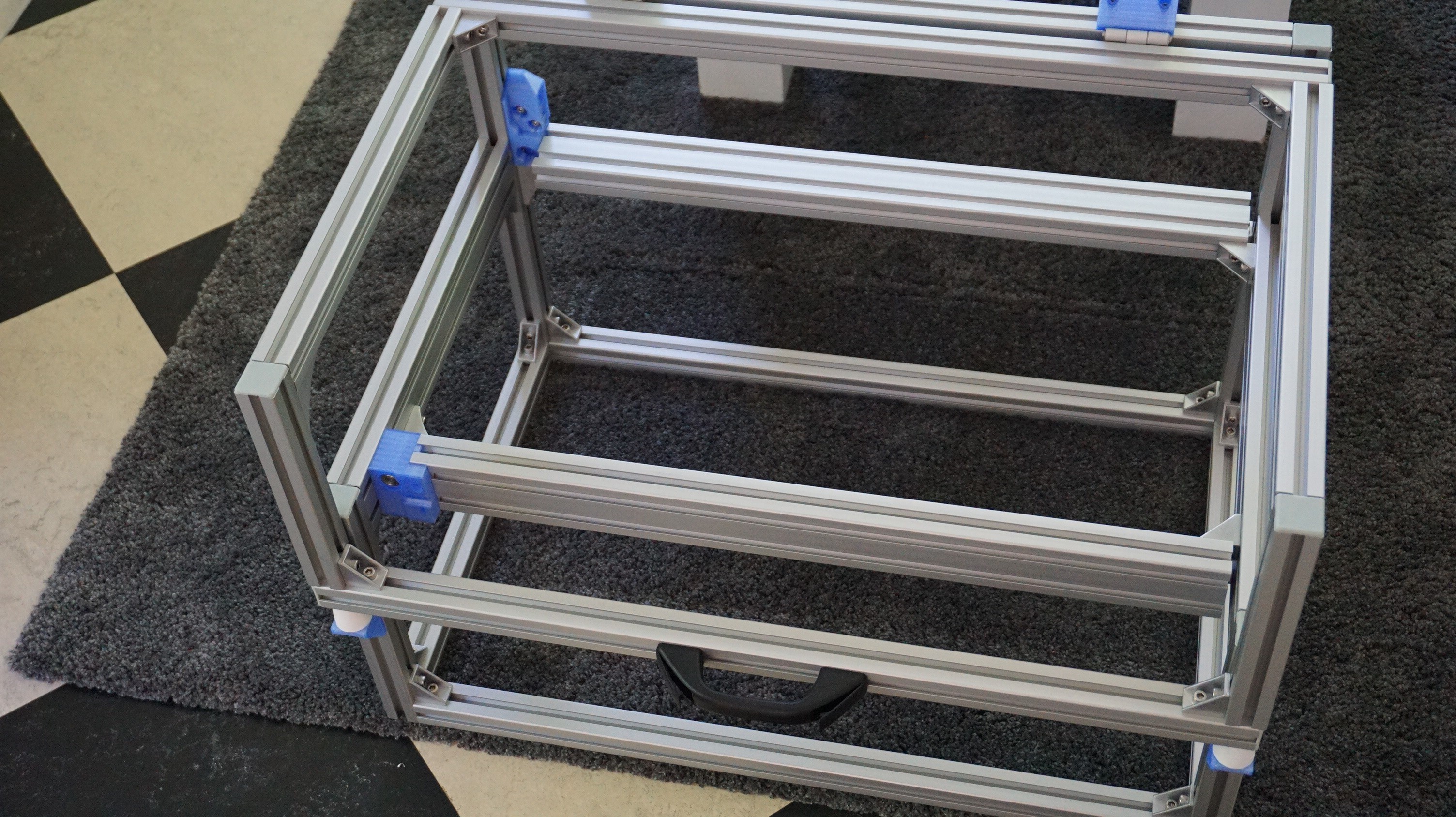
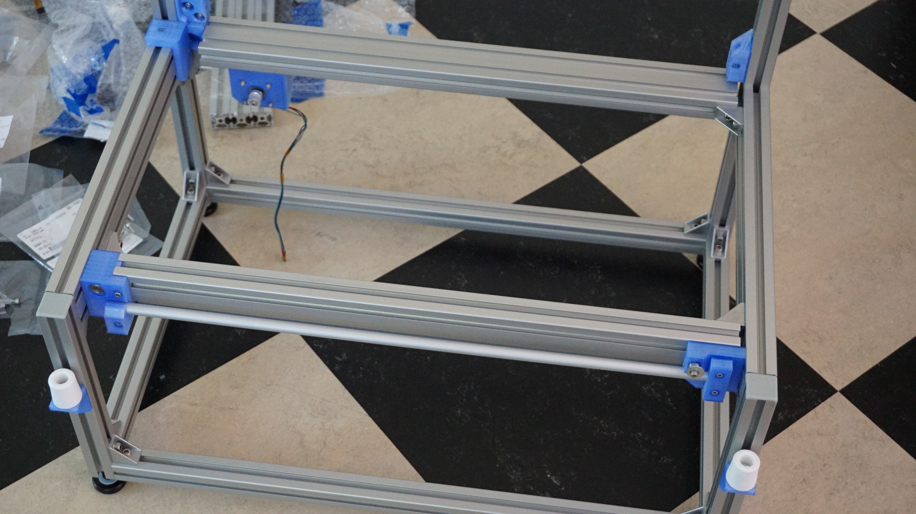
    The first component that needs to be built is the base frame. In the drawings this is Y10. The drawings for these parts are: OA-Y10-A01-00 (frame) and OA-Y10-A02-00 (Lid). It is easiest to start with the 2 sides, then add the middle profiles to it. The bottoms of the side frames need to be tapped M8 to hold the feet. The 2 30x60 profiles do not reach all the way. They are 30mm short to allow passage of the X driveshaft and belt.

View all 15 instructions

Enjoy this project?

Share

Discussions

Involute wrote 05/02/2018 at 18:59 point

When do you expect to make your first print?  Also, wouldn't you expect the CISS HP45 to last for more than a liter?

  Are you sure? yes | no

fik3 wrote 03/19/2018 at 15:32 point

Interesting project but how do you replace ink ?

Do you use cartridge till end but that could damage it ?

  Are you sure? yes | no

Yvo de Haas wrote 03/19/2018 at 21:50 point

The HP45 is a fairly easy printhead to fill. It does not have a sponge but a hollow chamber that is kept at a slight vacuum using a spring. Filling it simply requires a hole to be drilled and capped after filling. This hole can also be used to drain the head. Alternatively, I have heard of draining the head using a centrifuge. Only challenge is keeping the preload on the spring while filling it.

I also plan to either buy or modify CISS HP45 heads (Continuous Ink Supply System). These have a small tube leading to them to feed new ink to the head. This way you can print from a tank and directly see the level.

The head has indirect ways of detecting that it is empty. The head has a temperature sensor. If this spikes quickly after a burst of inkjet, you can assume the head is empty. All of the energy will not be deposited in the ink, but remains in the head. If the head gets past a certain temperature, there is an error. If this happens a few times in a row, the head can be assumed to be empty.

  Are you sure? yes | no

Elliot Williams wrote 03/18/2018 at 21:47 point

I really want to see this work. :)

  Are you sure? yes | no

peter jansen wrote 03/17/2018 at 18:31 point

This is a really exciting project.  A long time ago I tried to jet photopolymer from an HP cartridge (with thermal heads), then from an Epson cartridge (with piezo heads).  You likely already know this, but the commercial systems that do this tend to use piezo heads with really large apertures, so that the liquids are easy to jet, don't have to be put through thermal cycles from the thermal heads, etc., and it just seems really challenging in ways that aren't entirely clear to me (not being a materials science) to get it to work well and repeatable, and to do it inexpensively.  Really interesting project, I'm excited to see what you come up with, and if you're able to get it working!

  Are you sure? yes | no

peter jansen wrote 03/17/2018 at 18:32 point

Also, have you thought about using a thin UV curing binder that's easy to jet, and then briefly curing each layer? 

  Are you sure? yes | no

Yvo de Haas wrote 03/18/2018 at 18:19 point

I am aware of the benefits of using piezo inkjet as opposed to thermal inkjets. Piezo generally lasts longer and has more flexibility on the fluids it can handle. However, thermal inkjets are not completely unreliable and piezo inkjet also has limitation. Several piezo systems cannot handle conductive fluids and piezo heads also fail or clog.

When you take into account the added cost of piezo heads (≈€150, Xaar 128) versus thermal heads (≈€15, HP45, excluding driver) and the fact that the Zcorp powder and inkjet printers also use HP printheads (HP only do thermal inkjet as far as I know), the HP45 seems like a reasonable head to use. As soon as you get into more exotic binders, the thermal inkjet does indeed start to become a limit, but most older powder and inkjet have used fancy water and alcohol mixes for a long time. I have already tested thermal heads to work on my older machines and I think it will be a good starting point for a new machine. 

I have considered several projects using piezo inkjet heads and UV resins (including your suggestion), but so far, I haven't done any. The scope of this project will not include it to keep the project manageable, but a followup might.

  Are you sure? yes | no

Krzysztof wrote 03/17/2018 at 15:09 point

How long does typical printhead like this last? Will it be able to jet out 1L of water/alcohol without breaking?

  Are you sure? yes | no

Yvo de Haas wrote 03/17/2018 at 18:10 point

I think 1L will be a bit much. The head only has 42ml of storage on it's own. I am not entirely sure if the life isn't more, I think the heads are refurbished and refilled after they are taken back, but 1L seems a bit much. 

Having said that, the head will not fail in one go, nozzles will start to break, and that is something that can be measured. Original printers using the head will just refuse to print, but you can compensate for broken nozzles in the software.

  Are you sure? yes | no

Does this project spark your interest?

Become a member to follow this project and never miss any updates